Meshing a Bottle Cap Model with the given Quality Criteria after Mid-surface extraction using ANSA
Objective:
- To check for the geometrical errors in the component and mesh with the given element Quality criteria.
- After meshing the component the thickness has to be assigned.
- Quality Criteria:
S.No
Quality Criteria
Value
1
Target/Average length
1
2
Minimum Length
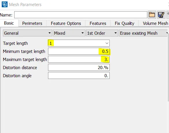
0.5
3
Maximum Length
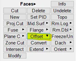
3
4
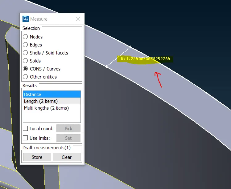
Aspect
3
5
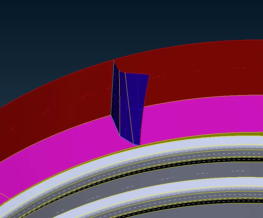
Warpage
15
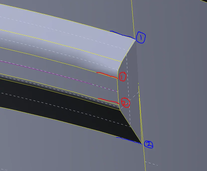
6
Skewness
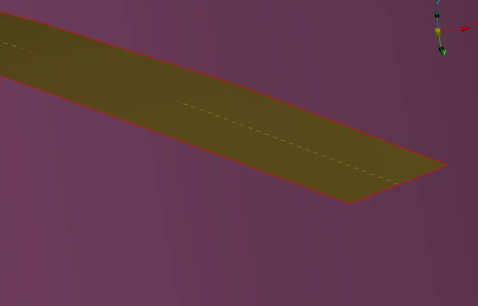
45
7
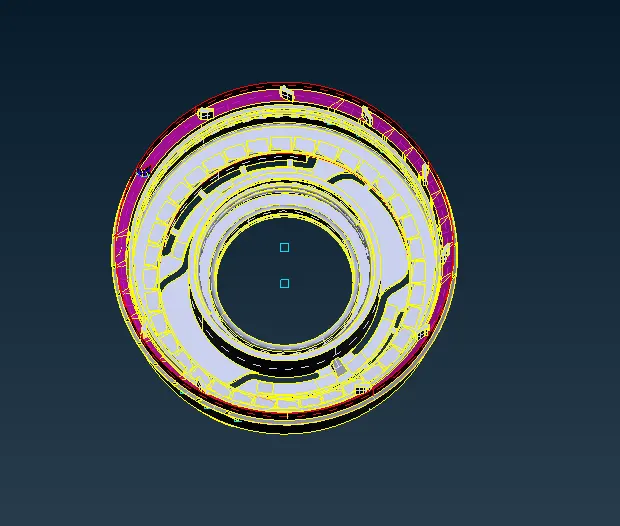
Jacobian
0.7
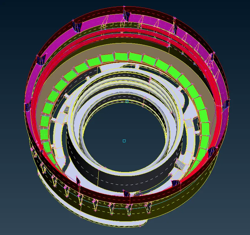
8
Minimum Quad Angle
45
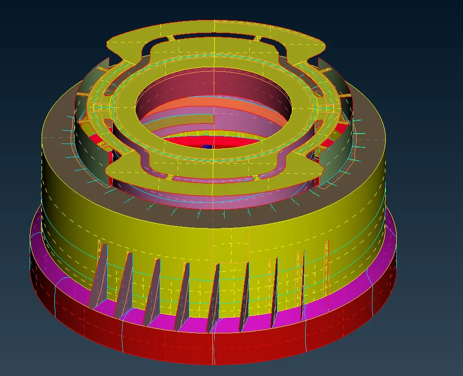
9
Maximum Quad Angle
135
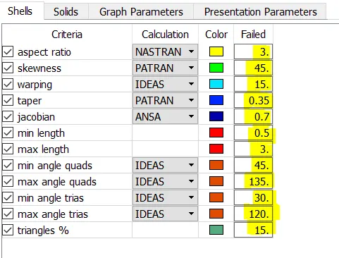
10
Minimum Tria Angle
30
11
Maximum Tria Angle
120
10
Tria Percentage
15
Procedure:
1. Open the given model in ANSA by going to File -> Open and selecting the IGS file.
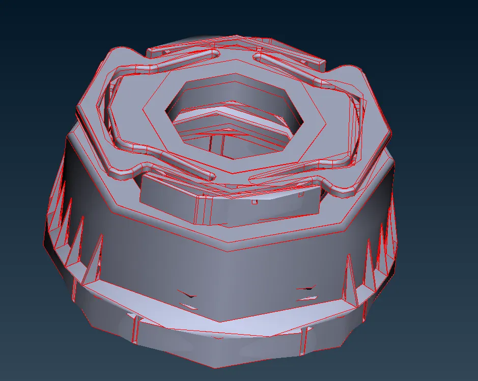
2. After importing the file will look as follows:
3. Perform a Topo on the whole component.
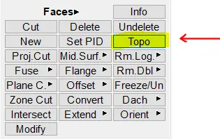
4. Go to Faces -> Topo and select the faces of the component
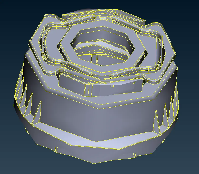
5. The component will looks as shown below:
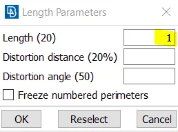
6. To get a more finer surface, go to mesh tab -> Perimeters -> length and select the the component and set the value as 1.
7. Do the same for macros as well.
8. The component will look as shown below:
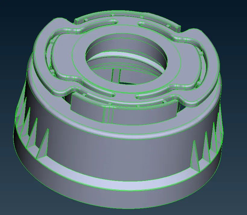
9. Next a geometry checkup needs to be performed.
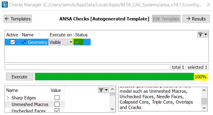
10. Go to the geometry checker and execute the check.
11. Fix any errors that pop up.
Mid-surface creation:
12. Next we move onto the mid-surface creation.
13. A manual mid-surface is created for this component.
14. There are 3 methods to create a manual mid-surface.
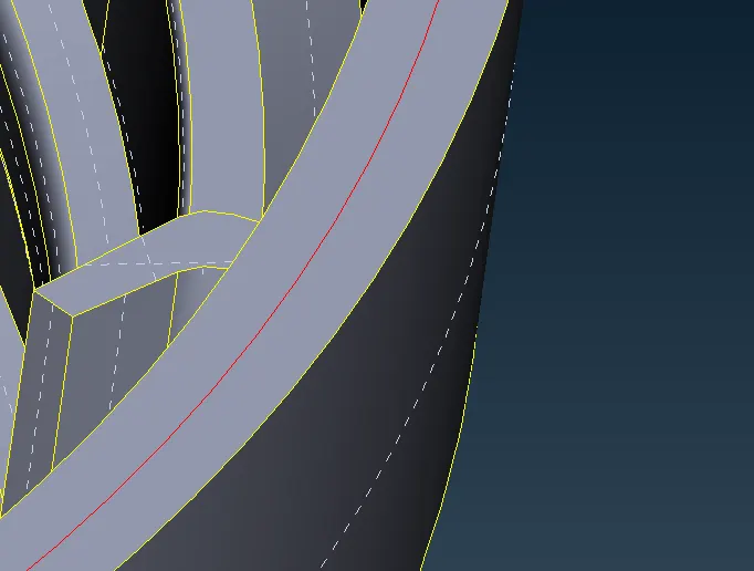
15. Method #1 : Offset faces:
16. Select the face that needs to be offset and set a value of offset to create the midsurface.
17. This is done for surfaces with a constant thickness.
18. Measure the thickness
19. Select the offset face and enter half the thickness value.
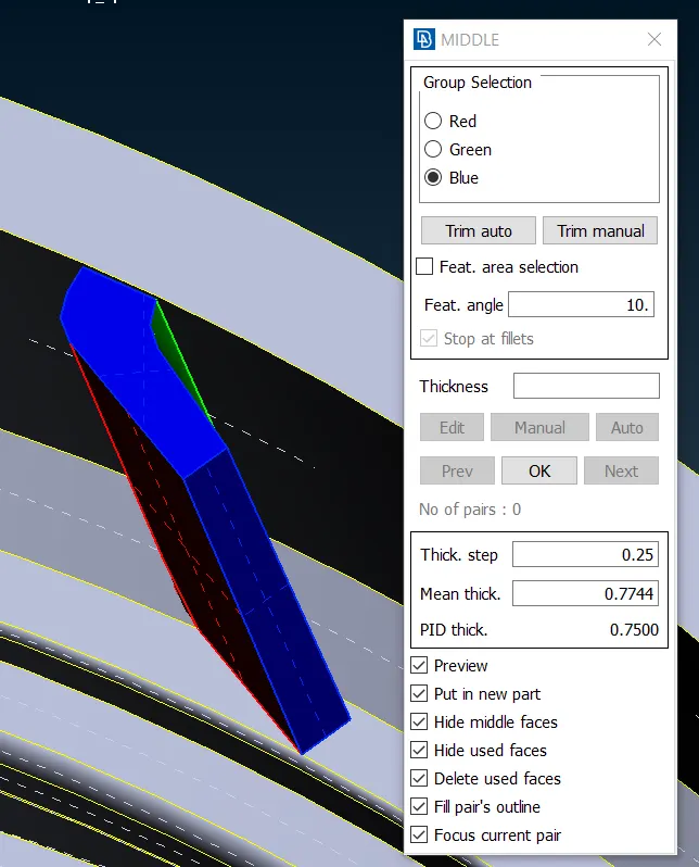
20. Method #2 : Faces -> Middle (single or multi)
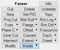
21. This option allows us to take the Mid-surface of parts with a varying thickness.
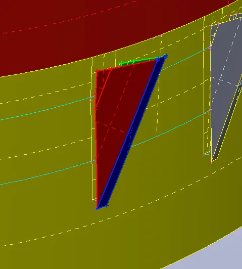
22. Extracted Mid-surface:
23. Method #3 : Creating mid-curves for threads
24. Create 2 mid- curves using the two pairs of lines as shown below:
25. The extracted Mid-surface will look as shown below:
26. The Rotate Command can be used to copy certain elements across a circular path.
27. The compoent shown below needs to be rotated for 12 instances along the circular face.
28. Set a COG for two circles as shown below:
29. Go to Transform -> Copy -> Rotate and select the entities to be rotated.
30. Select the points as x and dx and then hit the middle mouse button.
31. The selected entities will get rotated as shown below:
32. Similarly the Mid-surface is extracted for the whole component as shown below:
33. Care is taken that there is proper connectivity among the surfaces and no surface is left hanging.
Meshing:
34. Next we move on to meshing the component.
35. Press f11 and set the quality criteria as shown below:
36. Mesh parameters are also set as shown:
37. Each surface is meshed individually making sure that quality is cleared.
38. The following rules are kept in mind while meshing:
a) While meshing a big part, start with the most complex surface.
b) Make sure that there is a good flow of elements.
c) No opposite trias should be present.
d) No trias should be touching each other.
e) Rotational quads should be eliminated.
f) No trias in the fillet /hem regions.
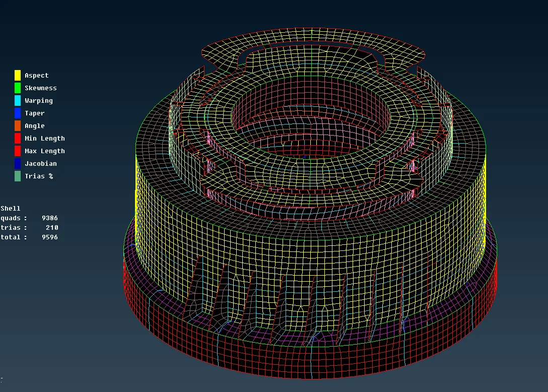
39. The meshed component looks as shown:
40. Assigning thickness:
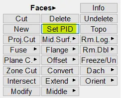
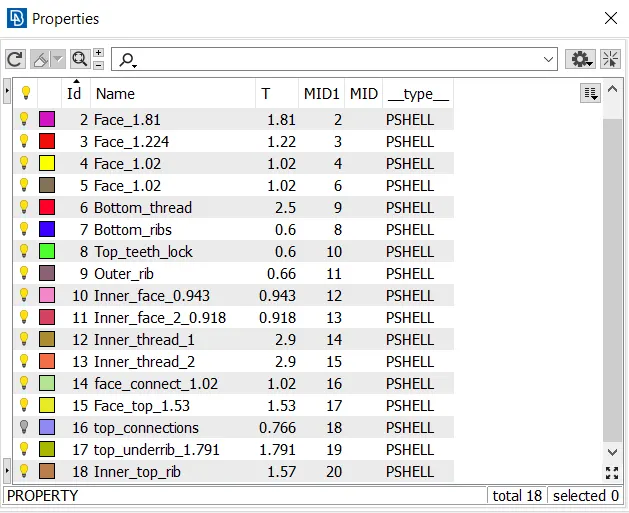
41. The features are measured and a thickness is assigned for the mid-surfaces as shown below using the set-PID option.
Result:
Learning Outcomes:
- Different types of Manual mid-surface extraction
- Rotate command
- Manual geometry cleaup
- Assigning thickness.
- Faster meshing methods.
Thus the given model was meshed for the given quality criteria after the extraction of a manual Mid-surface.