Week 2 Challenge : Surface meshing on a Pressure valve
AIM:- To Perform Surface Meshing On Pressure Valve.
OBJECTIVE:-
- To Check Geometry Errors and perform Topology Clean-up.
- To perform Mesh for Target length = 1mm, 3 mm and 5 mm (i.e. 3 cases) and Element type = Tria.
PROCEDURE:-
- Import Geometry:-
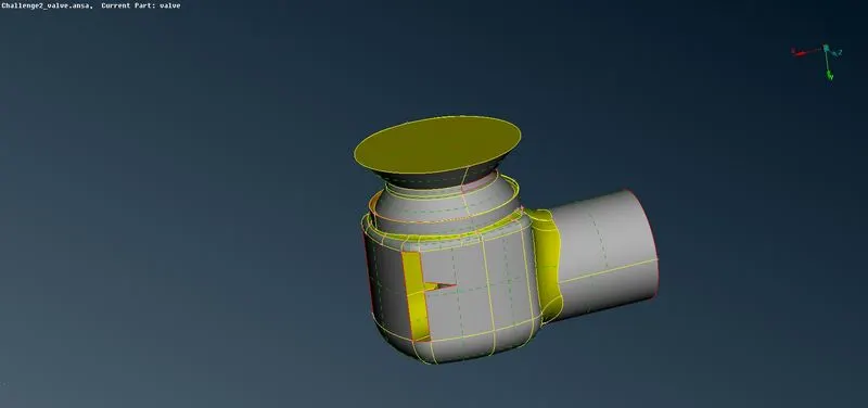
Fig.1 Imported Geometry
- Geometry Checks and Toplogy cleanup:-
First of all need to check the Geometry Errors by using geometry Checks option as shown in below fig. in fig we can see that found Single cone erros and Crack errors. single cone errors means two surfaces not shared with each other means geometry having some opening and holes as shown in Fig. 1. thats why Below Errors are occured.
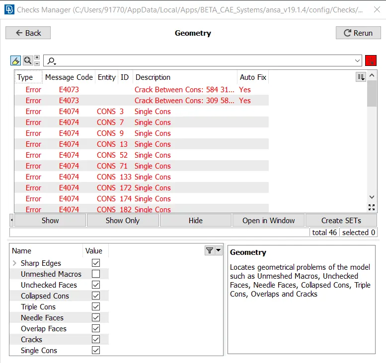
Then we have to Avoid Above Errors by using some Topology Clean-up methods as below.
In TOPO Deck we have some Options (Tools).
1. TOPO>Faces>New
This function defines a new surface by selecting its boundary curves and creates a corresponding face that covers the new surface. The calculated surface appears as a net.
2. TOPO>CONS>Fill Hole
Function Name : Fill Hole
This function fills holes on Faces. The holes can be of any shape. Such internal openings can be selected individually, or automatically among the visible ones if they fall below a user specified diameter value. There is the option to create automatically 3D Curves, Points or Connection Points of the removed holes, in order to mark their shape and position for reference.
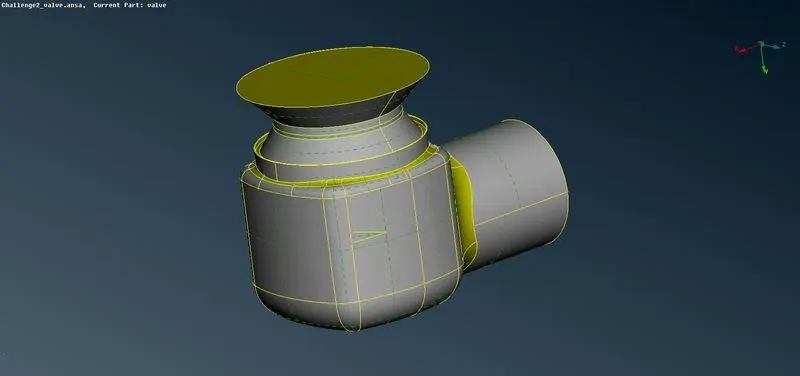
After Cleanup we can get geometry as below finally we are getting closed geometry for CFDtype of Meshing.
- ASSIGN PID's:-
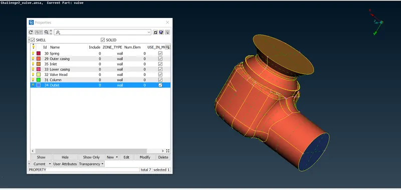
When we are using Mesing here so we have to assign Separate Component Name for Eaisier Meshing and apply Boundary conditions so we can use here PID means Property ID. by using Boolean Functions We can assign PID as >> Right click on PID name –Apply –Select the part that we need to assign that name –Selection of the part can be done using ENT mode (will select entity wise), PID mode ( will select PID wise) or PID region ( will select region wise taking any discontinuity in connection as one entity) –ok
- MESHING:-
Before Meshing we have to Check the Smaller surface than Target Length. By Join it Should be matched.
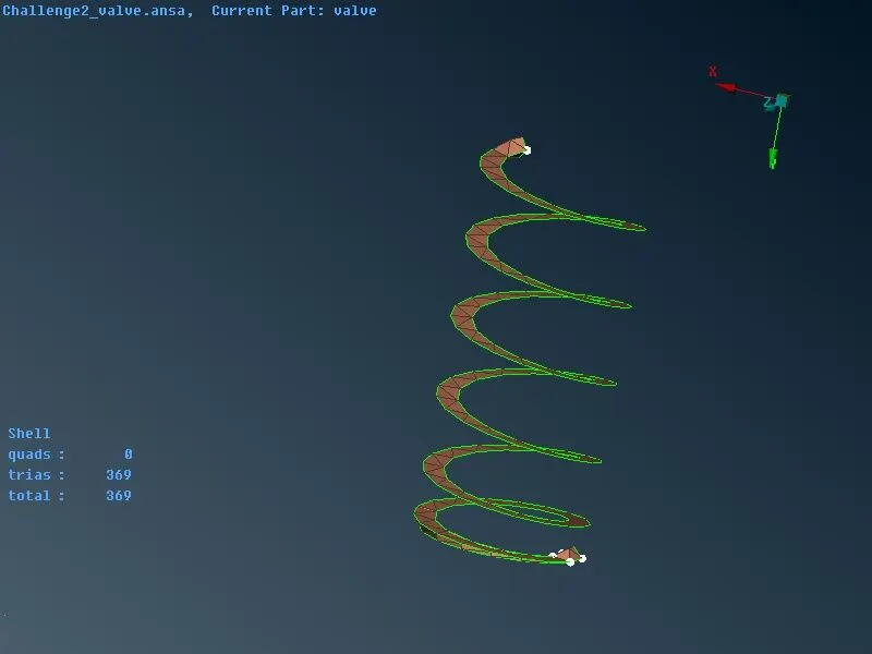
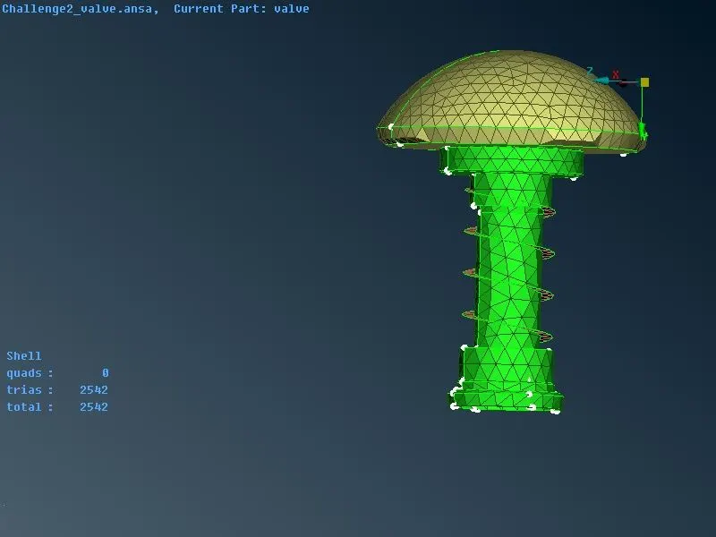
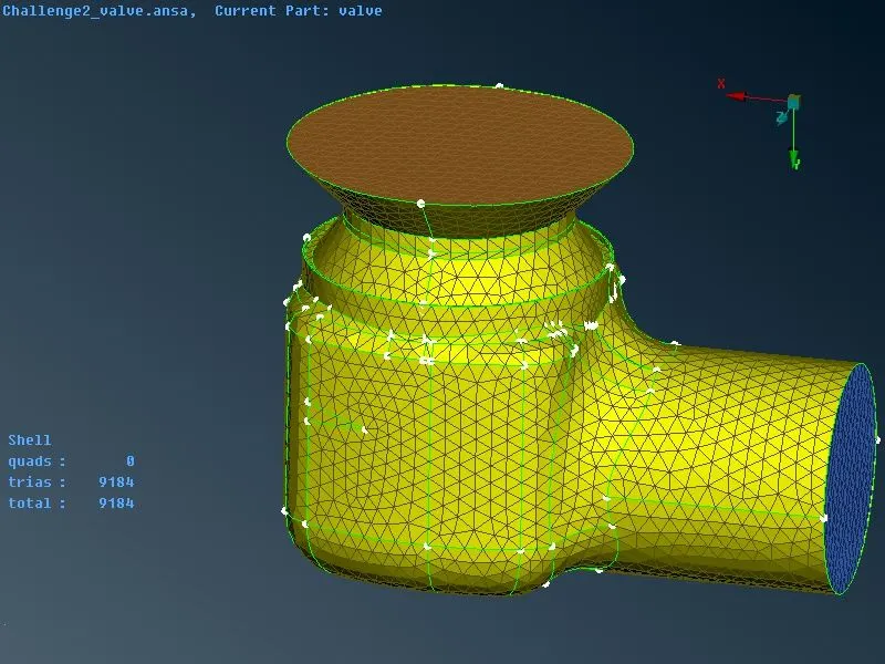
CASE-I:- Mesh Target Length is 5 mm
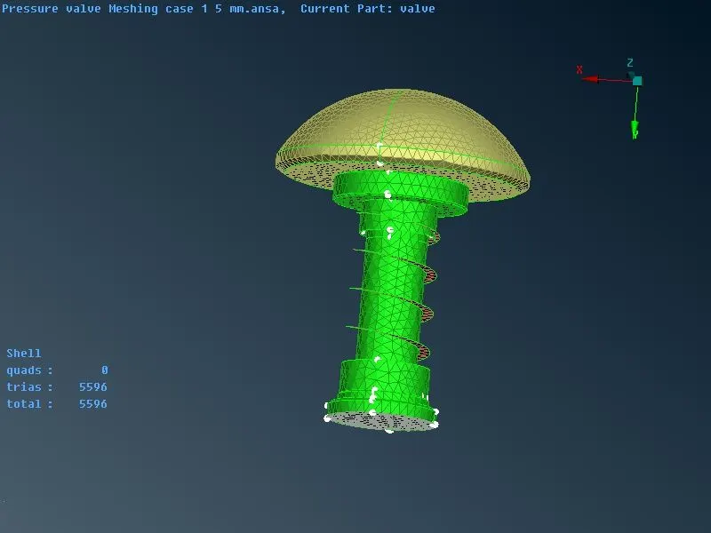
Here we set Target Length for Mesh Property and Mesh Quality is 5 mm. we used CFD Mesh for Meshing.
Spring:-
Valve Head, Spring and Column:-
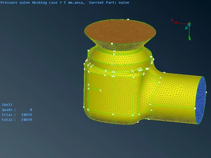
Outer Casing:-
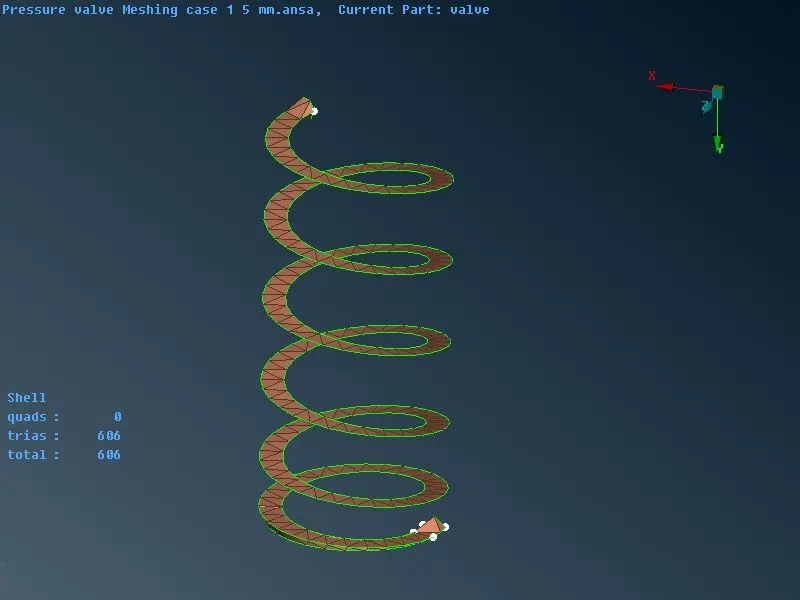
CASE-II:- Mesh Target Length is 3 mm
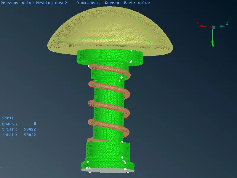
Here we set Target Length for Mesh Property and Mesh Quality is 3 mm. we used CFD Mesh for Meshing.
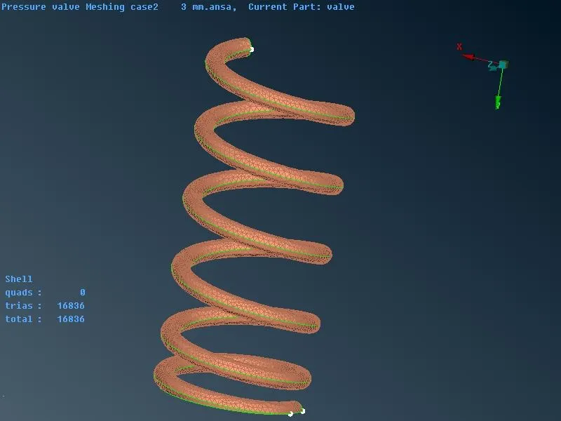
Spring:-
Valve Head, Spring and Column:-
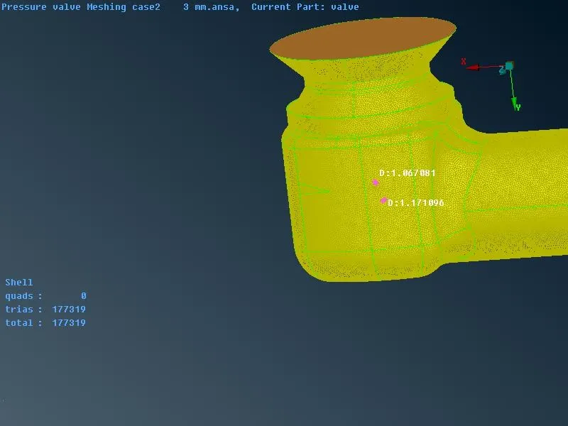
Outer Casing:-
CASE-III:- Mesh Target Length is 1 mm
Here we set Target Length for Mesh Property and Mesh Quality is 1 mm. we used CFD Mesh for Meshing.
Spring:-
Valve Head, Spring and Column:-
Outer Casing:-
CONCLUSION:-
1. Mesh size of 1mm will be more suitable as compared to 5mm and 3mm due to accuracy in capturing exact profiles of spring and head which are free from any distortion of surfaces.
2. Geometry Errors Checks and Topology are Checked for Various Target Length.
3. Change in Total Mesh element Size for Particular Target Length as shown in Table
| Case No | Target Length | Total Element Size/Tria |
| 1 | 5 mm | 9184 |
| 2 | 3 mm | 20319 |
| 3 | 1 mm | 177319 |
4. Spring can not be Meshed in Mesh Target Length 3 mm and 5 mm, because Diameter of Spring is less than 3 mm. So Target length for Spring Should be 1 mm for perfect Mesh.
FILES:-
5 mm :-
https://drive.google.com/file/d/1-Cr0RXOFhV456QXQfaJYwelnti7jXlJH/view?usp=sharing
3 mm:-
https://drive.google.com/file/d/1lhp-_xR4iBd02PcBXoBPmqM4yNa_gJdr/view?usp=sharing
1 mm:-
https://drive.google.com/file/d/1tFIeS9Vi2aM0HlhyhBr3TVa5idlkhv2-/view?usp=sharing