Week 9 - Parametric study on Gate valve.
AIM:- To perform a Simulation of Parametric study on Gate valve.
OBJECTIVE:-
Perform a parametric study on the gate valve simulation by setting the opening from 10 % to 80%.
- Obtain the mass flow rates at the outlet for each design point.
- Calculate the flow coefficient and flow factor for each opening and plot the graph.
- Discuss the results of the mass flow rate and flow coefficient.
INTRODUCTION:-
- Our objective is to simulate the flow through a gate valve by making the parametric study to analyze the flow rate at the outlet of the gate valve for different levels of gate valve disk.This gate disk valve is used to start or stop the fluid flow.
- The gate valve consists of a hand wheel and a spindle that is connected to the gate disk.The hand wheel and spindle together controls the level of gate disk.
- Gate Valve:-
A gate valve can be defined as a type of valve that uses a gate or wedge type disk,and the disk moves perpendicular to flow to start or stop the fluid flow in piping .A gate valve is the most common type of valve used in any process plant .
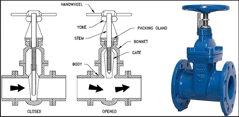
Applications Of Gate Valve:-
Gate valve flow characteristics. Gate valves are used in many industrial applications including the oil and gas industry, pharmaceuticals, manufacturing, automotive, and marine. Non-rising stem gate valves are very popular on ships, in underground applications, or where vertical space is limited because they don't take up extra space.
MODELING AND SIMULATION APPROCH:-
We are going to parametric study on the gate valve simulation by setting the opening from 10 % to 80%. means Gate Disc Lift will vary by 10 mm for each case.
First we are going to perform for 10 mm Disc lift.
- Geometry Preparation:-
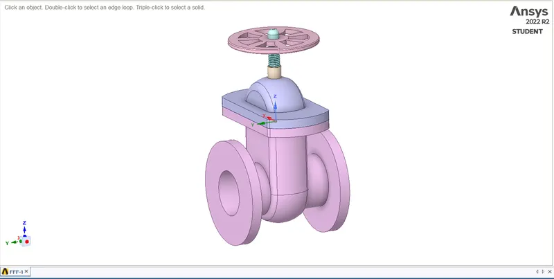
1) Import Geometry:- The geometry having Hand wheel, spindle, bonnet Gate Disc and Bottom.
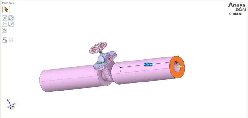
2) Extend the Flanges up to 800 mm to Both Side by using Pull tool, for better Capture the Flow Results.
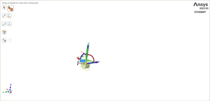
3) Set the 10 mm Disc Lift Parameter by ising the Move Tool for First Design Point parameter.
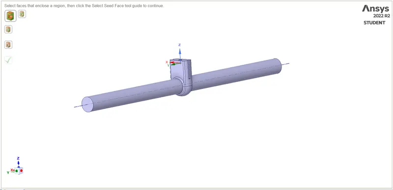
4) Create the Volume zone by using Volume Extract Tool.
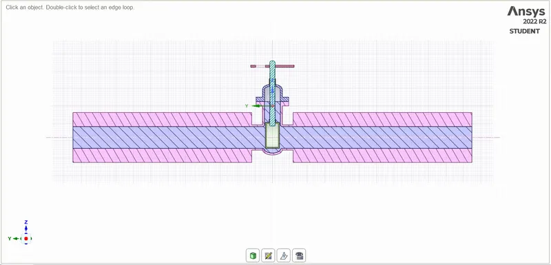
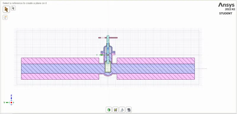
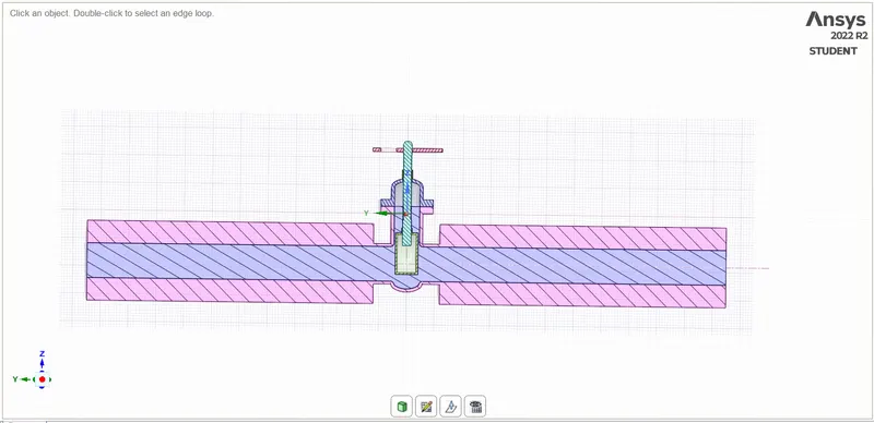
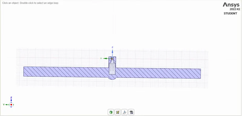
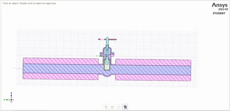
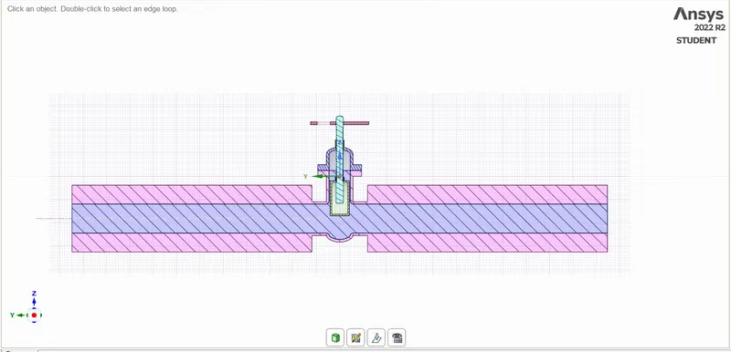
5) Section view along the YZ palne of geometry: (10mm lift)
- Meshing:-
1) After Geometry Preparation started with Meshing and We are using Tetrahedron type of Elements for meshing.
2) We are using 7 mm Mesh Size for this model.
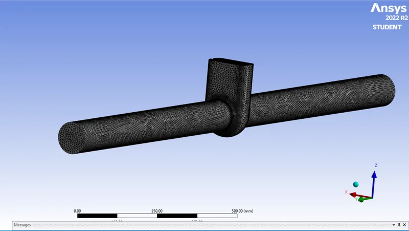
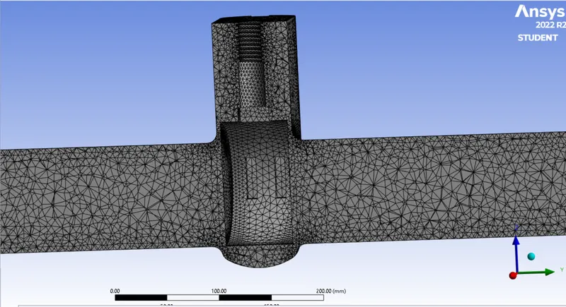
3) Details Of Mesh as below:-
The Mesh size will be 7 mm. The Total No. of Mesh Elements Will be 315705.
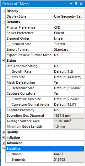
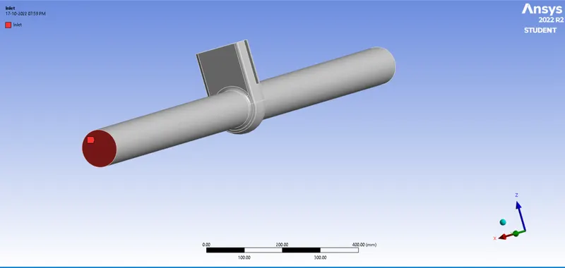
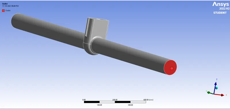
4) Create Named Selection:-
we are created Named Selection as Inlet and Outlet.
- Solver:-
| 1 | Solver | Pressure Based- Steady- Absolute |
| 2 | Gravity | ON:- -9.81 m/s^2 at Z Direction |
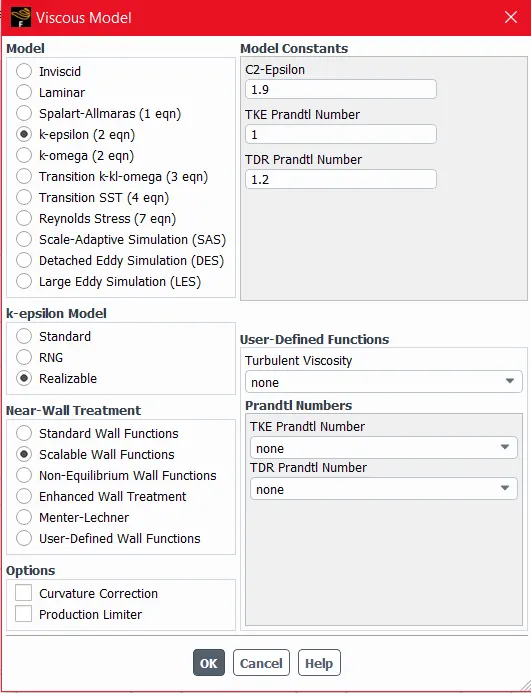
| 3 | Viscous Model | K-epsilon, Realizable , Scalable Wall Function |
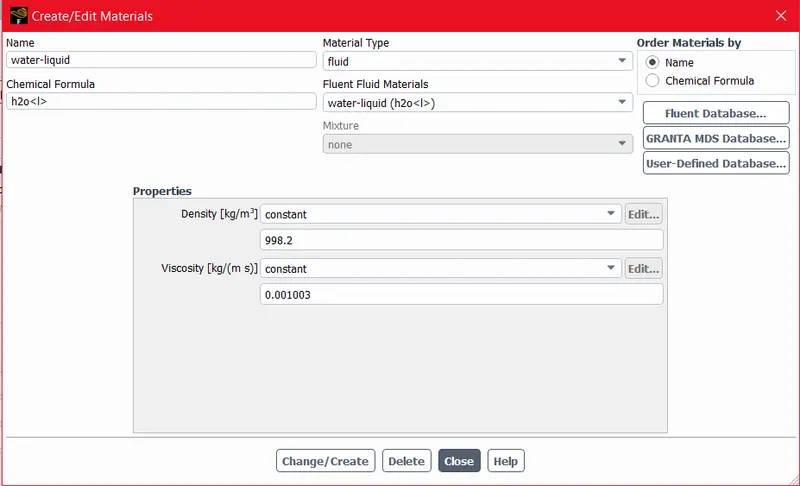
| 4 | Fluid Material | Liquid-Water |
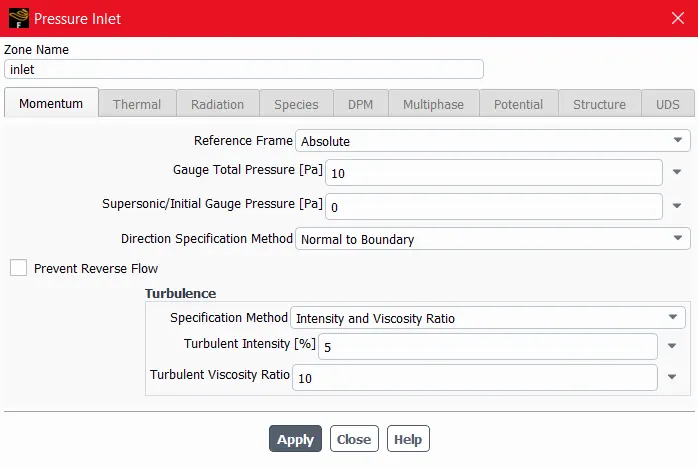
| 5 | Boundaries | 1.Inlet :- Pressure Inlet with 10 pa Pressure 2.Outlet:- Standerd Pressure Outlet 3.Interiour:- interiour volume 4.Wall:- Wall |
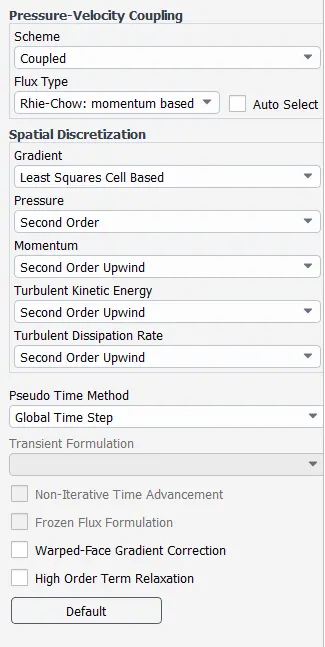
| 6 | Solution Method | Coupled- Second Order Upwind pseudo Time Method |
| 7 | Initialization Method | Hybrid Initialization |
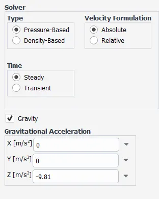
Viscous Model:-
Material for Fluid:-
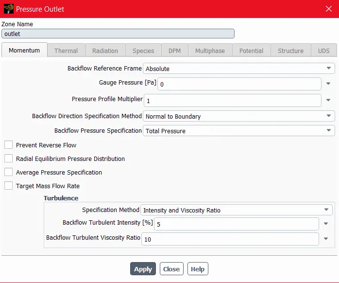
Boundary Conditions:-
1) Pressure Inlet:- we are using Pressure Inlet boundary condition with 10 pa Constant Pressure.
2) Pressure Outlet:- Standard Pressure outlet.
3) Interiour:- interiour volume
4) Wall:- No slip Wall
Solution Method:-
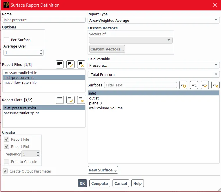
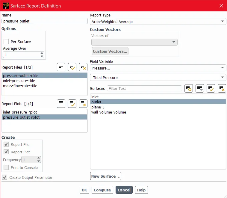
Creating Reports:-
1) Pressure inlet Report
2) Pressure Outlet Report
3) Mass Flow Report
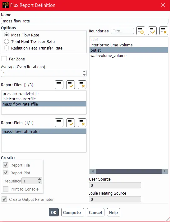
Creating Countour:-
1) Velocity Contour
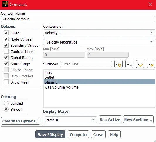
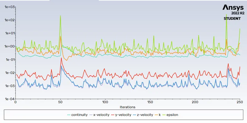
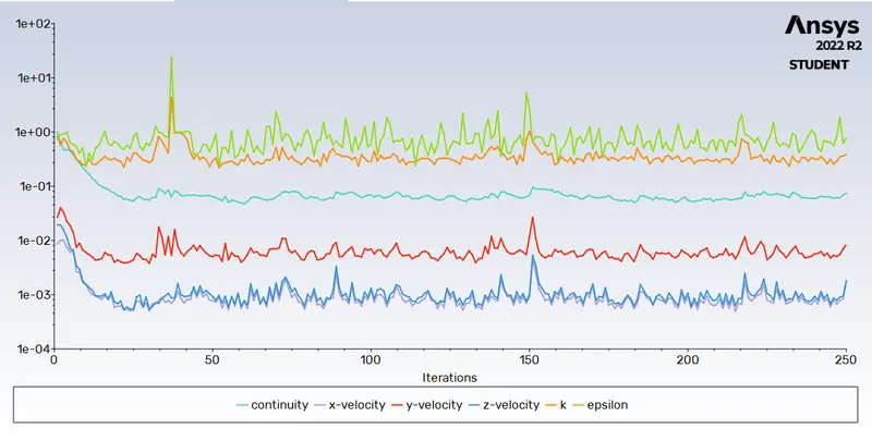
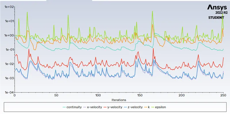
After completing above steps Run the calculation for 250 iterations.
- Results:-
For Case- 1:- 10 mm Disc Lift
Residual Plot:-
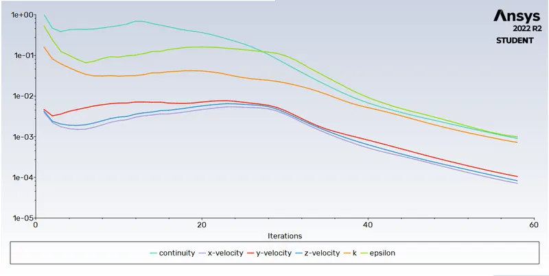
Inlet Pressure Plot:-
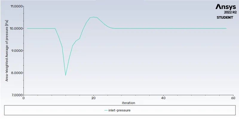
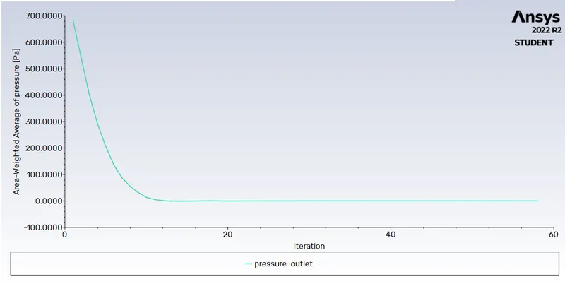
Outlet Pressure Plot:-
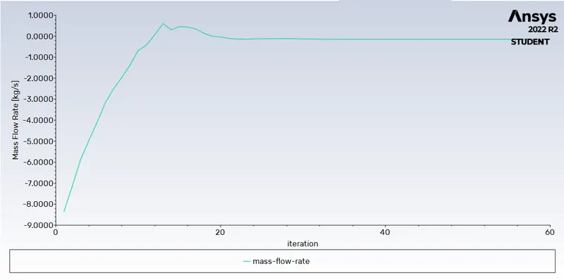
Mass Flow Rate Plot:-
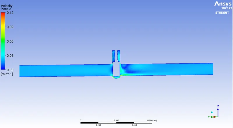
Velocity Contour:-
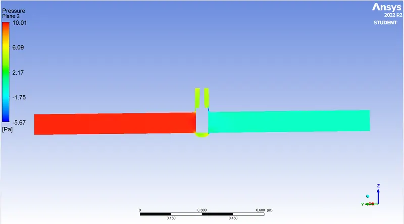
Pressure Contour:-
Velocity Vector:-
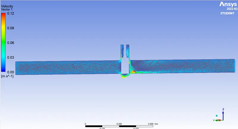
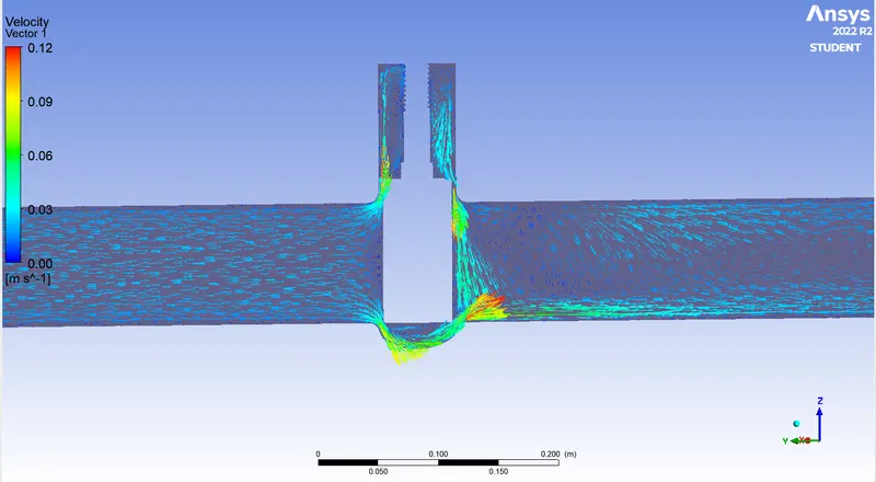
Flow coefficient :
The flow coefficient of a device is a relative measure of its efficiency at allowing fluid flow. It describes the relationship between the pressure drop across an orifice valve or other assembly and the corresponding flow rate.
Mathematically the flow coefficient `C_v`can be expressed as :
`C_v=Q*sqrt ((SG)/(Delta P))`------------------eq (1)
where:
Q is the rate of flow (expressed in US gallons per minute),
SG is the specific gravity of the fluid (for water = 1),
ΔP is the pressure drop across the valve (expressed in psi).
Flow Factor (`K_v`) :
The flow of water with temperature ranging`5-30^(0)C` through a valve in cubic meters per hour (`m^3/h`) with a pressure drop of 1 bar .
The relationship between flow coefficient and flow factor can be expressed as :
`K_v =0.865* C_v`----------(2)
We are calculate the flow coefficient and flow Factor for 10 mm lift
mass flow rate = 0.1488 kg/sec , 1kg/sec=15.85 gal/min ,
so Q = 0.1488* 15.85= 2.35 gal/min ,
SG (specific gravity) for water =1
ΔP = Pressure at inlet - pressure at outlet = 9.8169 pa , 1pa =0.000145psi
ΔP =0.00142 psi
Put this values in eq (1)
`C_v` = 62.3455
put this value in eq (2) we get
`K_v` =53.9288
For Case- 2:- 20 mm Disc Lift:-
Geometry:-
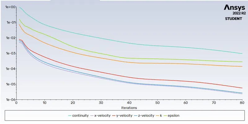
Residual Plot:-
Pressure Outlet plot:-
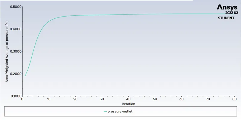
Mass Flow rate plot:-
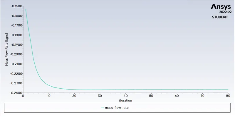
Pressure Contour:-
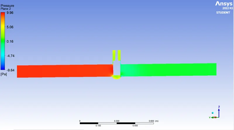
Velocity Contour:-
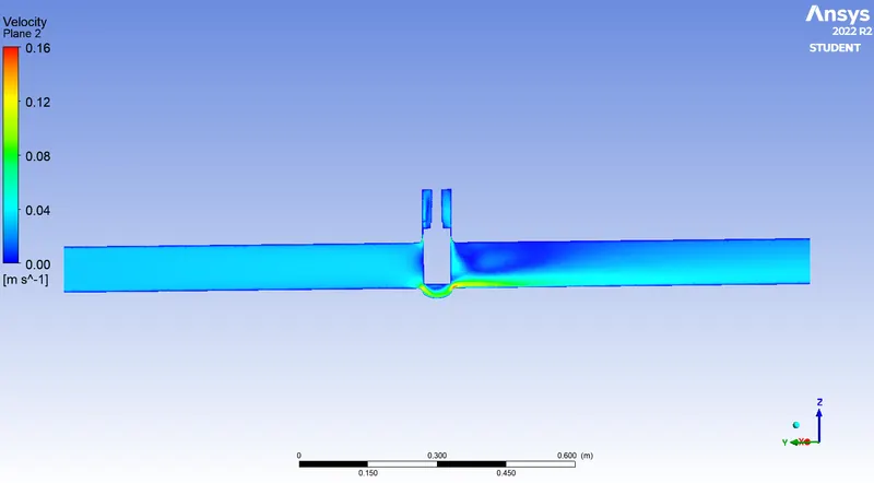
Velocitry Vector:-
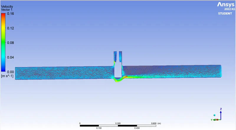
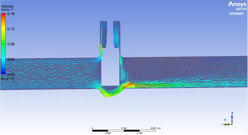
Now We are calculate the flow coefficient and flow Factor for 20 mm lift
mass flow rate = 0.2367 kg/sec , 1kg/sec=15.85 gal/min ,
so Q = 0.2367 * 15.85= 3.7516 gal/min ,
SG (specific gravity) for water =1
ΔP = Pressure at inlet - pressure at outlet = 9.5323 pa , 1pa =0.000145psi
ΔP =0.00138 psi
Put this values in eq (1)
`C_v` = 101.79
put this value in eq (2) we get
`K_v` =88.05
For Case- 3:- 30 mm Disc Lift:-
Geometry:-
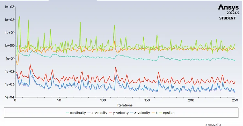
Residual Plot:-
Pressure Outlet plot:-
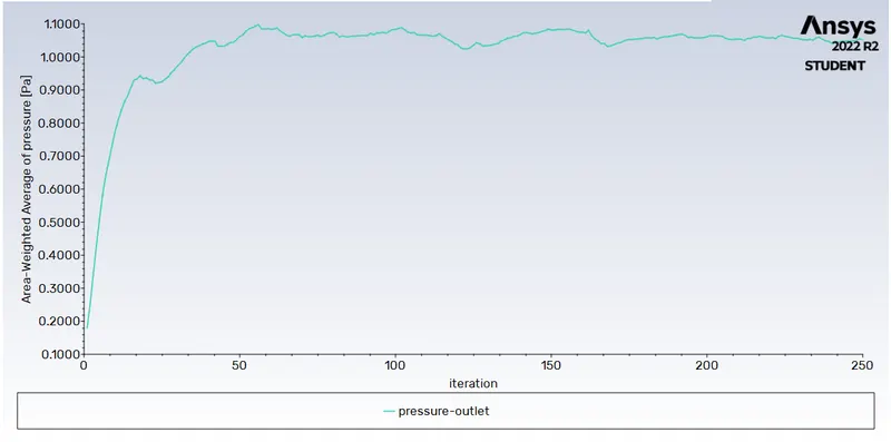
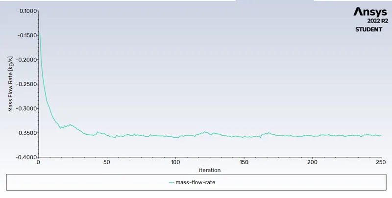
Mass Flow Rate plot:-
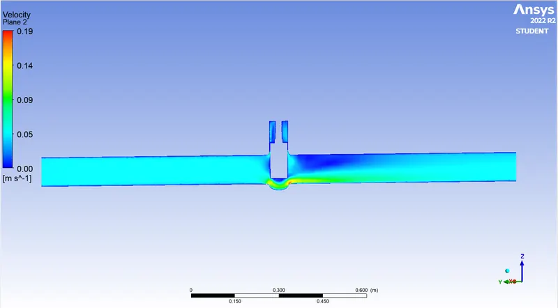
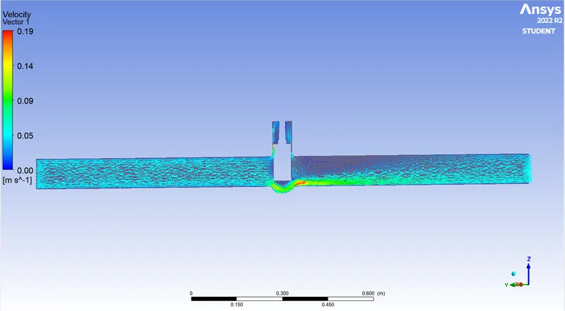
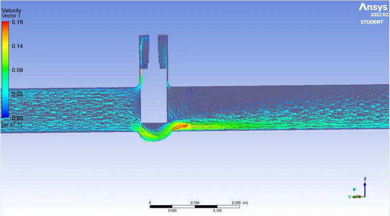
Velocity Contour:-
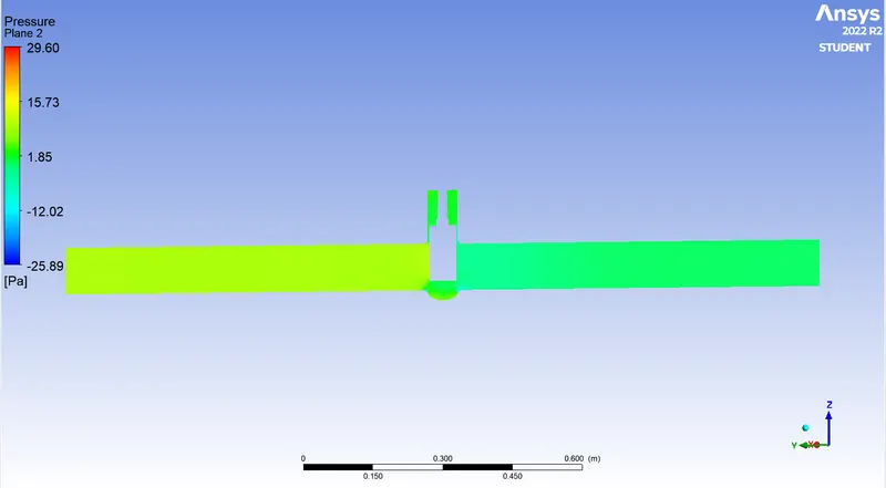
Pressure Contour:-
Velocitry Vector:-
Now We are calculate the flow coefficient and flow Factor for 30 mm lift
mass flow rate = 0.3549 kg/sec , 1kg/sec=15.85 gal/min ,
so Q = 0.3549 * 15.85= 5.6251 gal/min ,
SG (specific gravity) for water =1
ΔP = Pressure at inlet - pressure at outlet = 8.9532 pa , 1pa =0.000145psi
ΔP =0.00129 psi
Put this values in eq (1)
`C_v` = 156.61
put this value in eq (2) we get
`K_v` =135.47
For Case- 4:- 40 mm Disc Lift:-
Geometry:-
Residual Plot:-
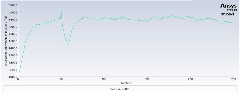
Pressure Outlet plot:-
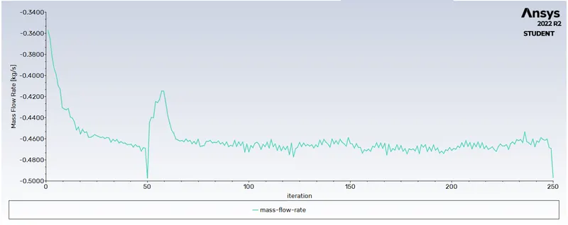
Mass Flow rate Plot:-
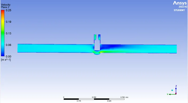
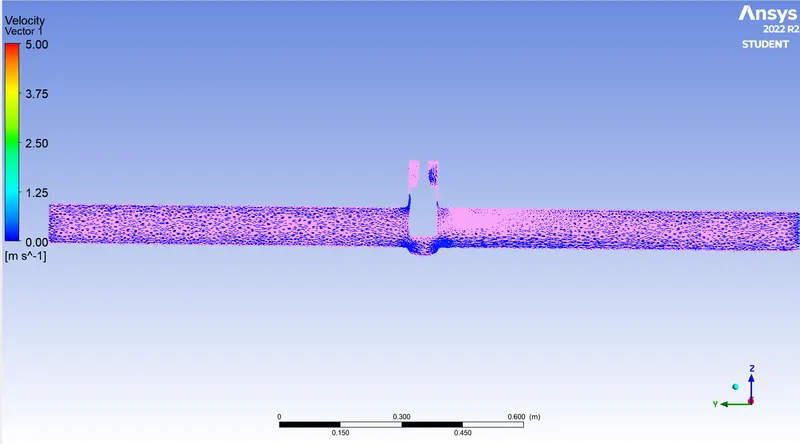
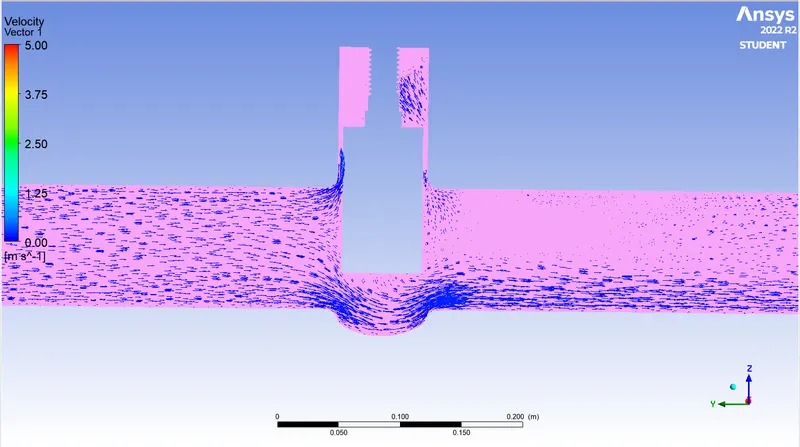
Velocity Contour:-
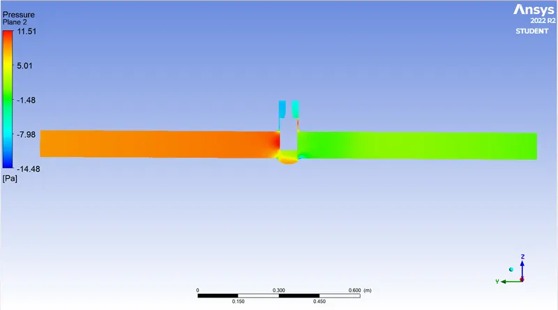
Pressure Contour:-
Velocity Vector:-
Now We are calculate the flow coefficient and flow Factor for 40 mm lift
mass flow rate = 0.4971 kg/sec , 1kg/sec=15.85 gal/min ,
so Q = 0.4971 * 15.85= 7.8790 gal/min ,
SG (specific gravity) for water =1
ΔP = Pressure at inlet - pressure at outlet = 8.0813 pa , 1pa =0.000145psi
ΔP =0.00117 psi
Put this values in eq (1)
`C_v` = 230.34
put this value in eq (2) we get
`K_v` =199.24
For Case- 5:- 50 mm Disc Lift:-
Geometry:-
Residual Plot:-
Pressure Outlet Plot:-
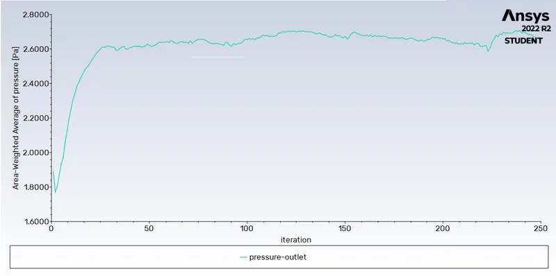
Mass Flow Rate Plot:-
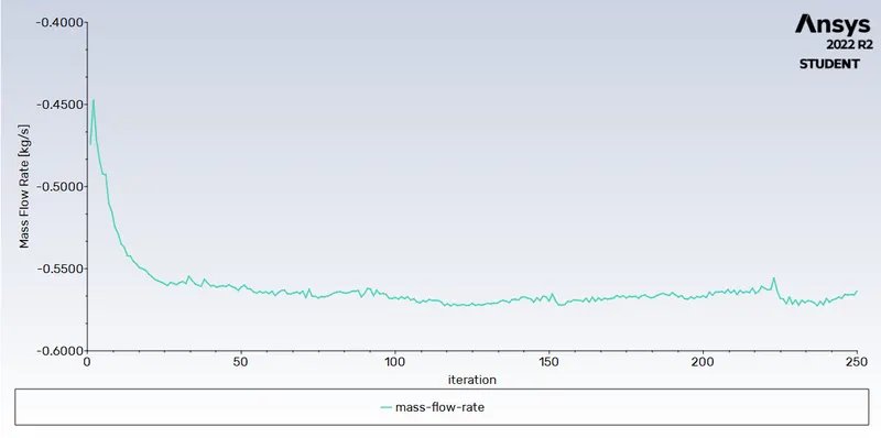
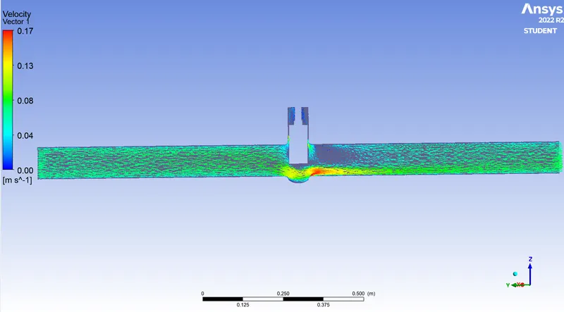
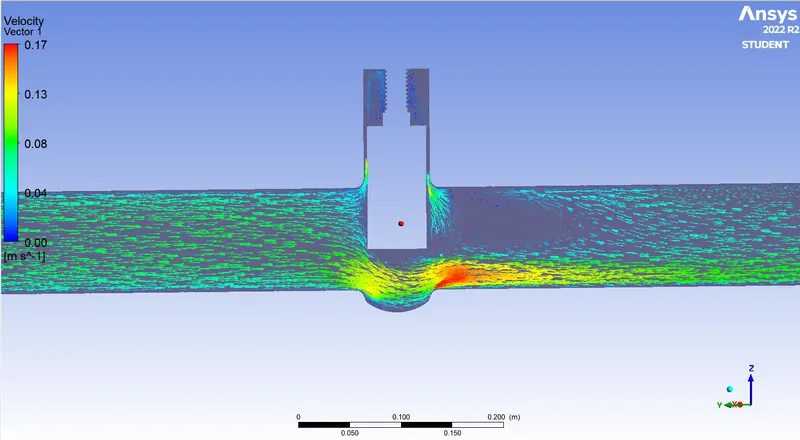
Velocity Contour:-
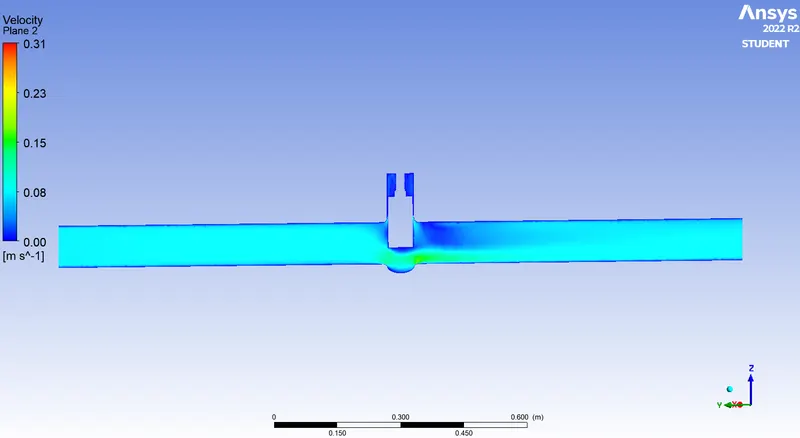
Pressure Contour:-
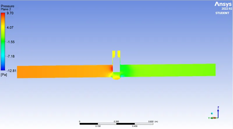
Velocity Vector:-
Now We are calculate the flow coefficient and flow Factor for 50 mm lift
mass flow rate = 0.5635 kg/sec , 1kg/sec=15.85 gal/min ,
so Q = 0.5635 * 15.85= 8.9314 gal/min ,
SG (specific gravity) for water =1
ΔP = Pressure at inlet - pressure at outlet = 7.4354 pa , 1pa =0.000145psi
ΔP =0.00107 psi
Put this values in eq (1)
`C_v` = 273.04
put this value in eq (2) we get
`K_v` =236.18
For Case- 6:- 60 mm Disc Lift:-
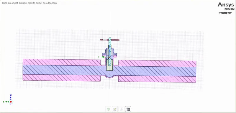
Geometry:-
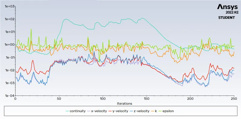
Residual Plot:-
Pressure Outlet Plot:-
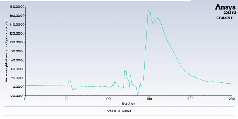
Mass flow Rate Plot:-
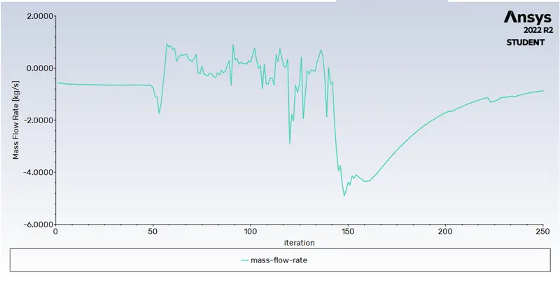
Velocity Contour:-
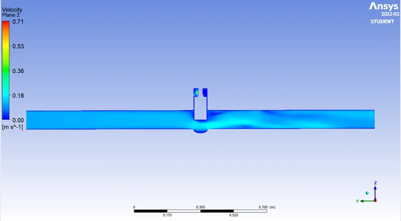
Pressure Contour:-
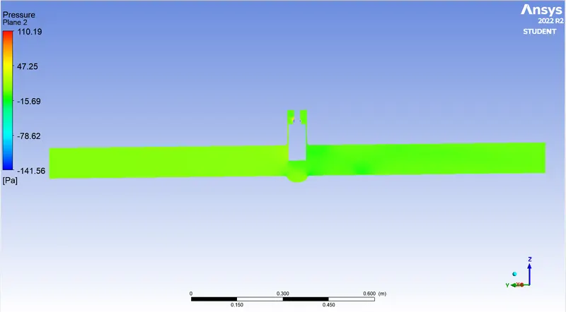
Velocity Vector:-
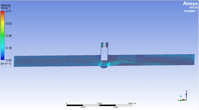
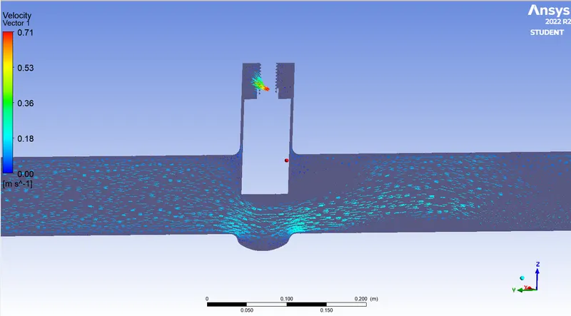
Now We are calculate the flow coefficient and flow Factor for 60 mm lift
mass flow rate = 0.8680 kg/sec , 1kg/sec=15.85 gal/min ,
so Q = 0.8680 * 15.85= 13.7578 gal/min ,
SG (specific gravity) for water =1
ΔP = Pressure at inlet - pressure at outlet = 3.1179 pa , 1pa =0.000145psi
ΔP =0.00045 psi
Put this values in eq (1)
`C_v` = 648.54
put this value in eq (2) we get
`K_v` =560.90
For Case- 7:- 70 mm Disc Lift:-
Geometry:-
Residual Plot:-
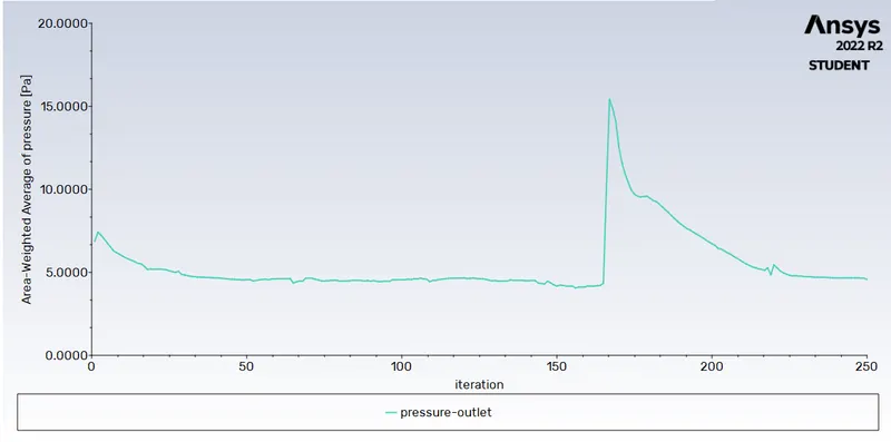
Pressure Outlet Plot:-
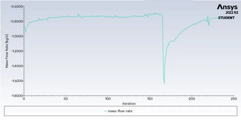
Mass flow Rate Plot:-
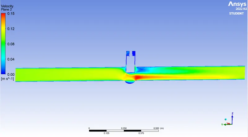
Velocity Contour:-
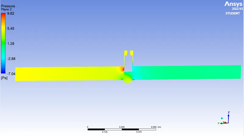
Pressure Contour:-
Velocity Vector:-
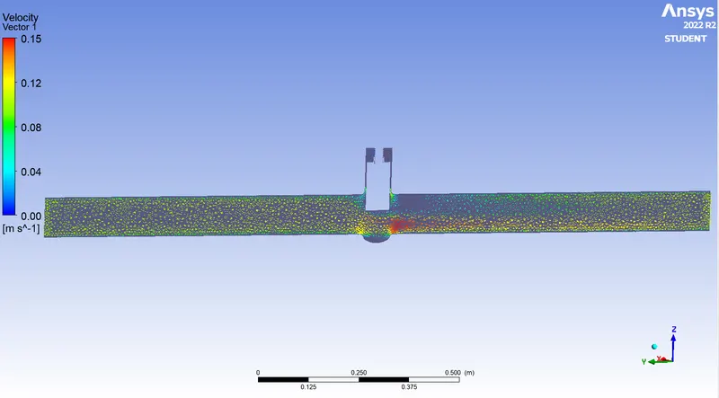
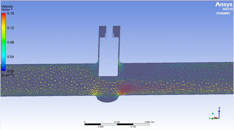
Now We are calculate the flow coefficient and flow Factor for 70 mm lift
mass flow rate = 0.7329 kg/sec , 1kg/sec=15.85 gal/min ,
so Q = 0.7329 * 15.85= 11.6164 gal/min ,
SG (specific gravity) for water =1
ΔP = Pressure at inlet - pressure at outlet = 5.4233 pa , 1pa =0.000145psi
ΔP =0.0042 psi
Put this values in eq (1)
`C_v` = 179.24
put this value in eq (2) we get
`K_v` =155.04
For Case- 8 :- 80 mm Disc Lift:-
Geometry:-
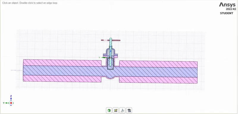
Residual Plot:-
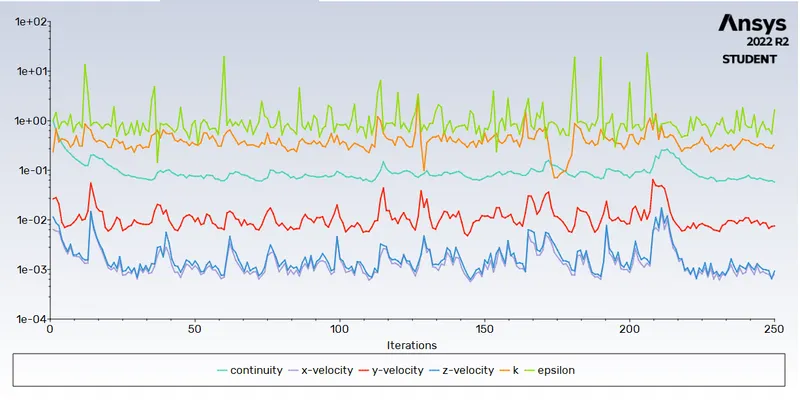
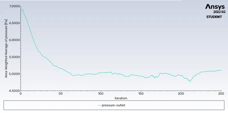
Pressure Outlet Plot:-
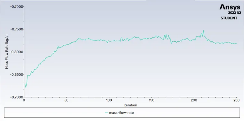
Mass flow Rate Plot:-
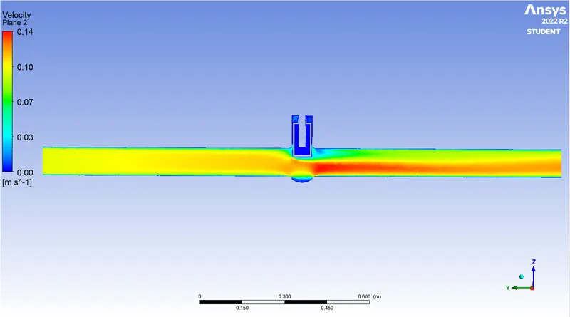
Velocity Contour:-
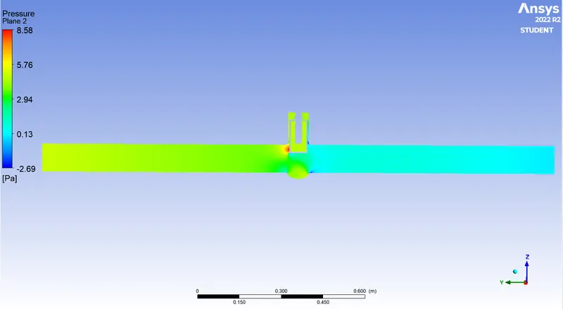
Pressure Contour:-
Velocity Vector:-
Now We are calculate the flow coefficient and flow Factor for 80 mm lift
mass flow rate = 0.7810 kg/sec , 1kg/sec=15.85 gal/min ,
so Q = 0.7810 * 15.85= 12.3788 gal/min ,
SG (specific gravity) for water =1
ΔP = Pressure at inlet - pressure at outlet = 4.9048 pa , 1pa =0.000145psi
ΔP =0.0007 psi
Put this values in eq (1)
`C_v` = 467.87
put this value in eq (2) we get
`K_v` =404.71.
RESULTS AND DISCUSSION:-
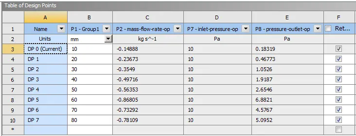
In below Figure we can see the 8 Design points having Disc Lift 10 mm to 80 mm Lift and Mass flow rate, Inlet Pressure and Outlet Pressure, Inlet pressure is same as 10 pa.
Table of design points:-
| Sr No. | Gate Disc Lift ( in mm) | Flow coefficient (Cv) | Flow factor (Kv) | Pressure Drop ( Δ P) in psi |
| 1 | 10 | 62.3455 | 53.9288 | 0.00142 |
| 2 | 20 | 101.79 | 88.05 | 0.00138 |
| 3 | 30 | 156.61 | 135.47 | 0.00129 |
| 4 | 40 | 230.34 | 199.24 | 0.00117 |
| 5 | 50 | 273.04 | 236.18 | 0.00107 |
| 6 | 60 | 648.54 | 560.9 | 0.00045 |
| 7 | 70 | 179.24 | 155.04 | 0.0042 |
| 8 | 80 | 467.87 | 404.71 | 0.0007 |
The graph of Gate disc lift vs flow coefficient is shown below:
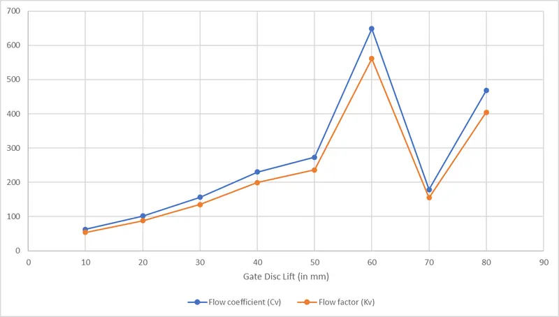
- From the observation of result table we can say that the mass flow rate is increases when we increase the gate disc lift of gate valve.
- The pressure drop is decreases when we Lifted the gate disc of gate valve
- The flow coefficient is also increases when we increase the gate disc lift of gate valve.
- The flow factor is also increases when we increase the gate disc lift of gate valve.
CONCLUSION:-
- We are Performed a parametric study on the gate valve simulation by setting the opening from 10 % to 80% as we can see the above Table and Graph Data.
- From the graph, it can be seen that mass flow increases rather slowly than flow factor & flow coefficient which show their exponential nature.
- Hence much larger flow coefficient & flow factor each time there is an increment in mass flow rate.
- The mass flow rate is increases if we increase the gate valve opening (gate disc lift) .
- The velocity of the flow is also increases when we increase the gate disc lift of gate valve.
- The pressure drop is decreases when we increase the gate disc lift of gate valve.
- The graph of flow factor and flow coefficient with respect to lift of the gate valve is plotted.
- The design point 70mm and 80 mm is not Showing correct results because the reason behind that is the bug in ansys student version.