Week 2 - Converging diverging nozzle
AIM:- To Simulate Flow inside the Converging diverging nozzle.
OBJECTIVE:- To simulate the Flow inside the converging diverging Nozzle
For the following boundary conditions,
- At Inlet, Pressure = 1atm and Temperature = 300K. The outlet pressure= 0.027 atm.
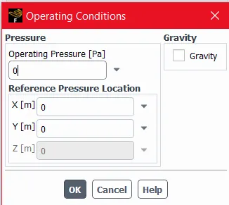
- In the operating conditions, consider the reference pressure to be zero.
THEORY:-
Convergent-Divergent Nozzle is a tube which is pinched in the middle, making a carefully balanced, asymmetric hourglass shape. It is used to accelerate a compressible fluid to supersonic speeds in the axial (thrust) direction, by converting the thermal energy of the flow into kinetic energy. Convergent-Divergent nozzles are widely used in some types of steam turbines and rocket engine nozzles. It also use in supersonic jet engines.
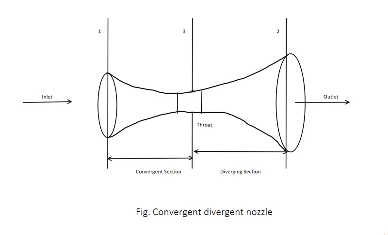
Its operation relies on the different properties of gases flowing at subsonic, sonic, and supersonic speeds. The speed of a subsonic flow of gas will increase if the pipe carrying it narrows because the mass flow rate is constant. The gas flow through a de Laval nozzle is isentropic (gas entropy is nearly constant). In a subsonic flow sound will propagate through the gas. At the "throat", where the cross-sectional area is at its minimum, the gas velocity locally becomes sonic (Mach number = 1.0), a condition called choked flow. As the nozzle cross-sectional area increases, the gas begins to expand and the gas flow increases to supersonic velocities where a sound wave will not propagate backward through the gas as viewed in the frame of reference of the nozzle.
SIMULATION:-
Stages of Simulation are as follows:-
- Geometry
- Mesh
- Set-up
- Solution
- Results
GEOMETRY PREPARATION:-
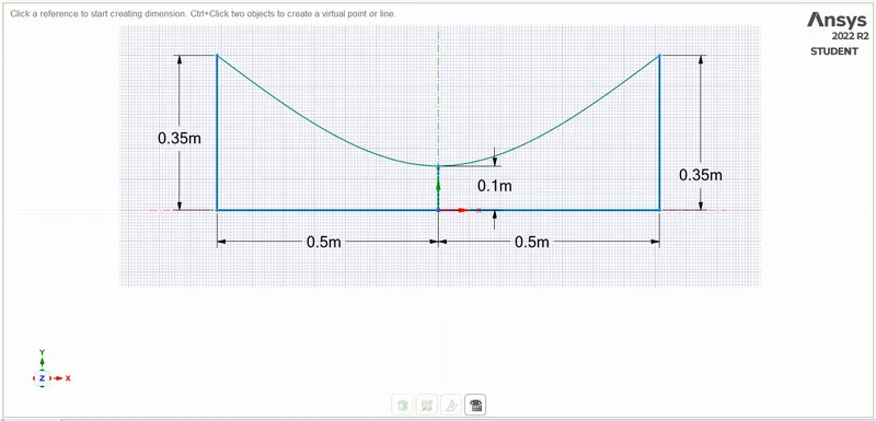
For geometry preparation createed geometry in spaceclaim as Dimensions As below:-
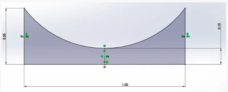
Generated Geometry:-
After generating geometry we need to use Pull tool for creating Surface.
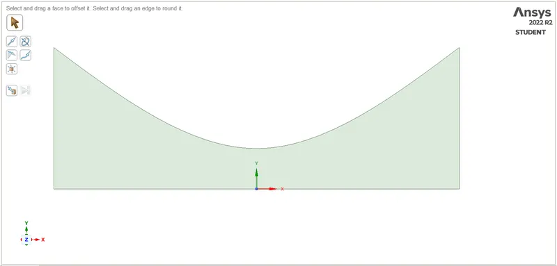
MESH:-
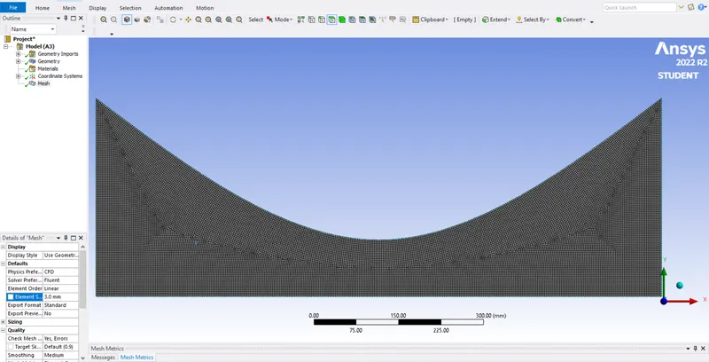
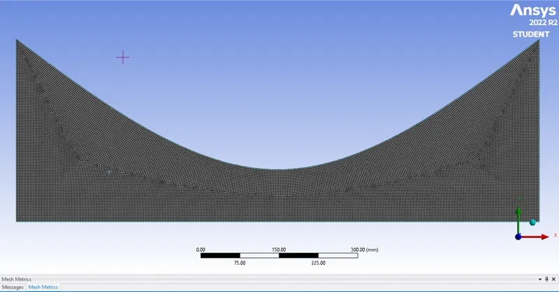
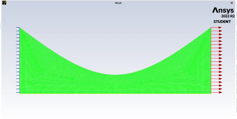
Generated Mesh:-
Here we Meshed Geometry by 3 mm Element Size and element is Quad.
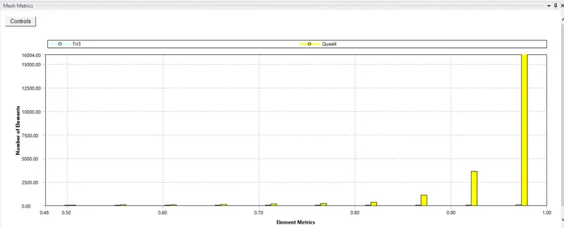
Mesh Quality:-
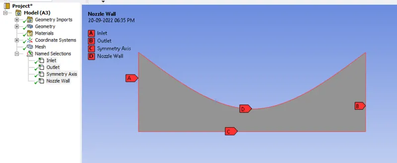
Then Define the Named Selection as below:-
- Inlet
- Outlet
- Symmetry Axis
- Nozzle Wall
SET-UP:-
After Meshing we are going to Set-up the Convergent Divergent Nozzle as per criteria.
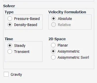
Solver Set-up:-
- Type:- Density-Based
- Time:- Steady
- Velocity Formulation :- Absolute
- 2D Space:- Axisymmetric
- Operating Conditions:-
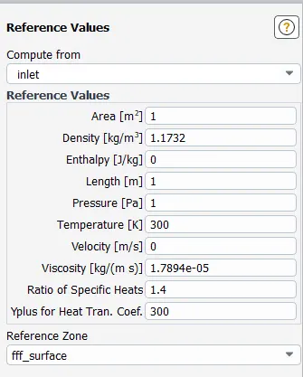
- Reference Values:-
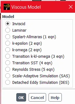
Viscous Model:-
Here we used Inviscid Viscous Model because we are using Ideal gas.
A flow in which viscous effects can be neglected is known as inviscid flow.
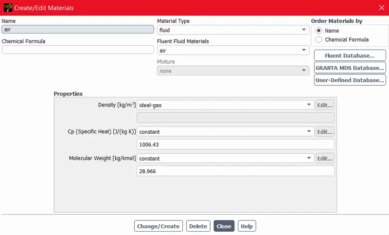
- Material:-
Boundaries:-
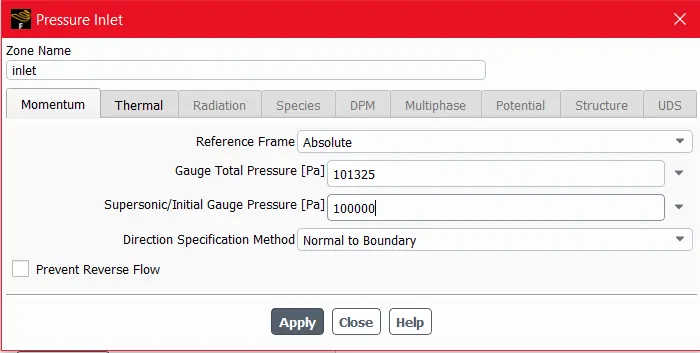
- Pressure Inlet:- 101325 pa
- Nozzle Wall:- Wall
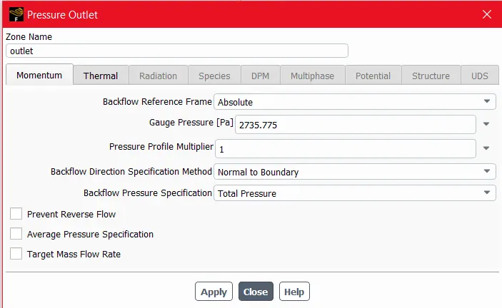
- Pressure Outlet :- 2735.775 pa
- Symmetry Axis:- Axis
Here we used Inlet Pressure Boundary condition.
- Pressure Inlet:-
- Pressure Outlet:-
RESULTS:-
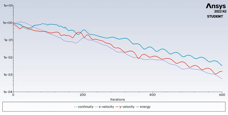
After setup all criteria we are going to calculate for 600 Iterations, then following results are obtained.
Residual Plot:-
Pressure Contour:-
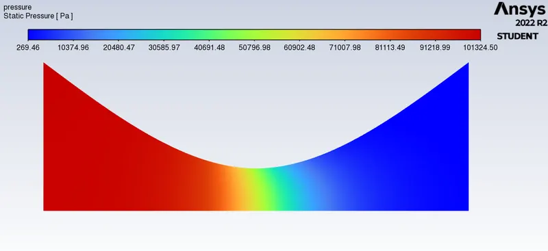
In Above fig we are clearly seen that Inlet Pressure is High (101324.50 pa) 1 atm. and Outlet Pressure is 2735.775 pa which is lower.
Velocity Contour:-
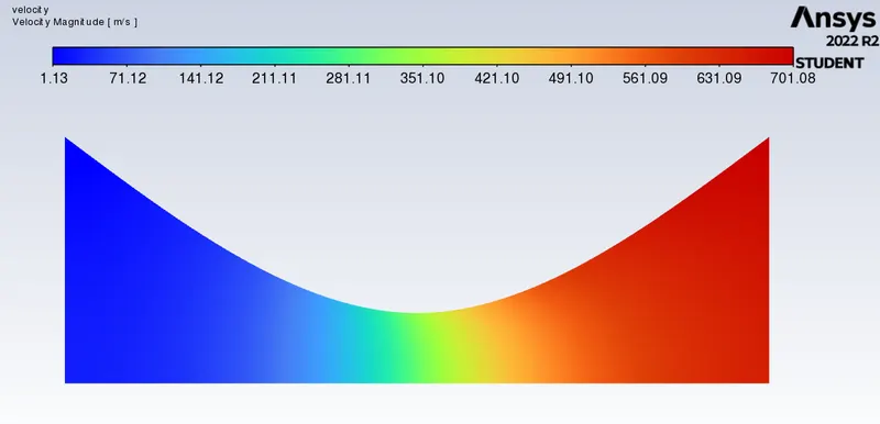
In Above fig we are clearly seen that Inlet Velocity is Low and Outlet Velocity is High.
Static Temperature Contour :-
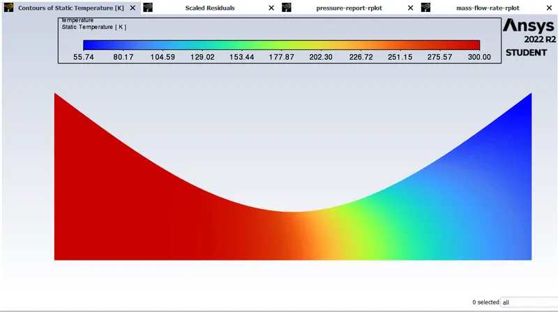
In Above fig we are clearly seen that Inlet Temperature is High 300 k and Outlet Temperature is Low. the all is happened due to High pressure at inlet and low pressure at outlet.
Mach Number Contour:-
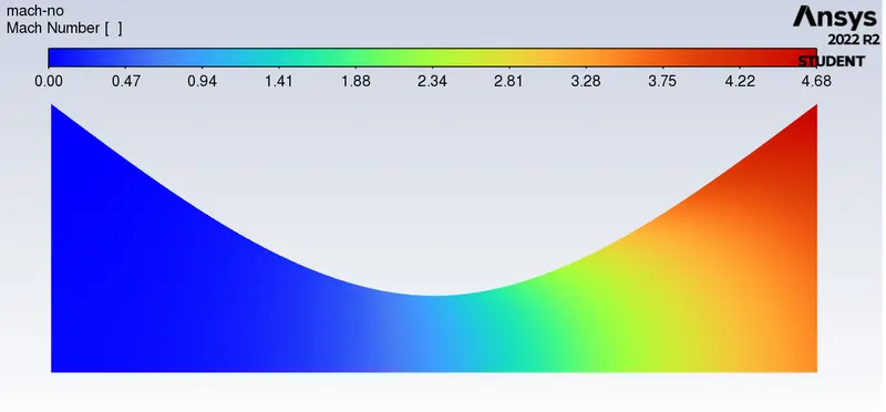
The Above shown contour is Mach Number as Ideal gas introduced in Inlet Mach No. is zero and it becomes Higher toward Outlet. also we can see the Mach no at throat region near to 1.
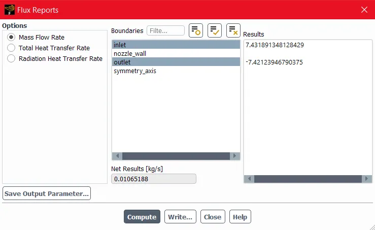
Mass Flow Rate :-
The Inlet mass flow rate is 7.4318 Kg/s and Outlet mass flow rate is -7.4212 Kg/s. So Net mass flow rate is 0.01065188 kg/s.
PLOTS :-
1. Pressure Distribution Over Nozzle Plot :-
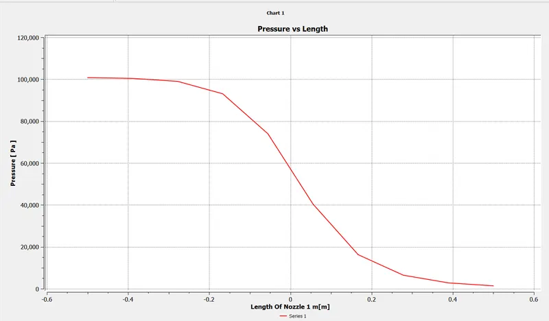
here in the above plot X axis is shown the Length of Nozzle (-0.5 to 0.5) is 1 meter and Y axis is Pressure in Pa. as we can see as we can go towards -0.5 to 0.5 ie inlet to outlet pressure keeps Decreasing.
2. Temperature Distribution Over Nozzele Plot :-
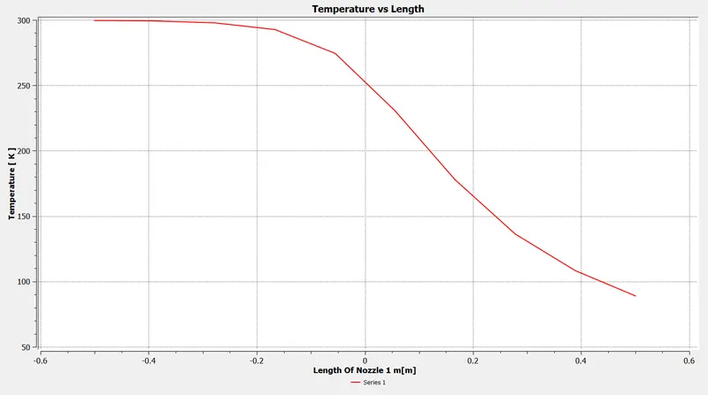
here in the above plot X axis is shown the Length of Nozzle (-0.5 to 0.5) is 1 meter and Y axis is Temperature in K. as we can see as we can go towards -0.5 to 0.5 ie inlet to outlet Temperature keeps Decreasing.
3. Velocity Distribution Over Nozzele Plot :-
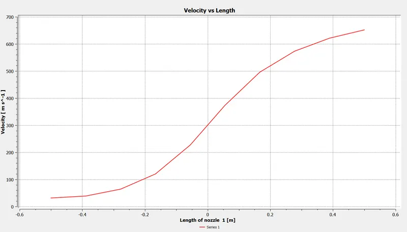
here in the above Plot X axis is shown the Length of Nozzle (-0.5 to 0.5) is 1 meter and Y axis is Velocity in m/s. as we can see as we can go towards -0.5 to 0.5 ie inlet to outlet Velocity keeps Increasing.
4. Mach Number Plot:-
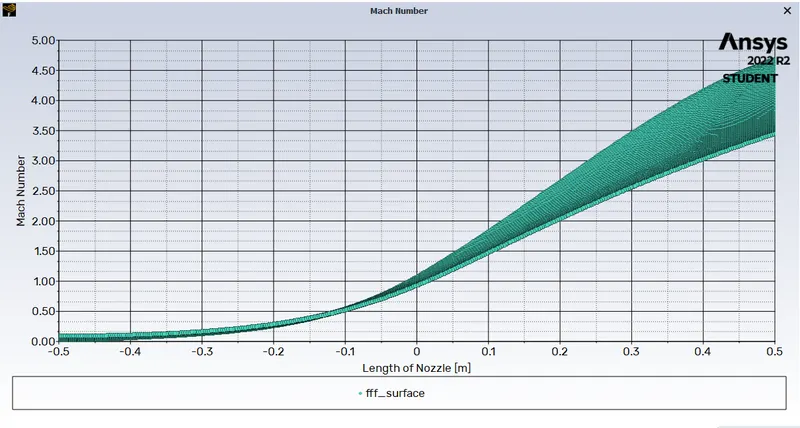
From above plot We can conclude that Mach no is 1 (M=1) at Throat Region and it starts to Supersonic from Throat region 0.517 m from inlet.
CFD VS ANALYTICAL:-
`(1 - M^2) * (dV )/ V = - (dA )/ A`
`(dA )/ A=( M^2-1) * (dV )/ V`
Now we can say thet This equation tells us how the velocity V changes when the area A changes, and the results depend on the Mach number M of the flow. If the flow is subsonic then (M < 1) and the term multiplying the velocity change is positive (1 - M^2 > 0). An increase in the area (dA > 0 ) produces a negative increase (decrease) in the velocity (dV < 0). For our CD nozzle, if the flow in the throat is subsonic, the flow downstream of the throat will decelerate and stay subsonic. So if the converging section is too large and does not choke the flow in the throat, the exit velocity is very slow and doesn't produce much thrust.
Now we can assume the Section 1 for Inlet and Section 2 for Outlet and Section 3 for Throat.
Now we can apply law of mass conservation
`dotm=rho*A*V=`Constant
`therefore (drho)/rho=(dA)/A=(dV)/V`
then we get, `(1 - M^2) * (dV )/ V = - (dA )/ A`
here we can conclude that apart from in the Throat region area is smaller means so Mach no will be Below 1 or equal to 1. and as area increased mach no will increse.
But in case of CFD Mach no at throat region is nearly equal to 1 so iflow becomes to sonic fro throat region.
CONCLUSION:-
- Simulation Results (Velocity Distribution, Pressure Distribution,Temperature Distribution and Mach Number are simulated for the converging and Diverging Nozzle.
- By using Both Analytical and CFD Approach we conclude the Mach no and Velocity Distribution as Mach No is Equal to 1 at the throat region. and Velocity and Pressure at inlet and Outlet.