Week 8 - Simulating Cyclone separator with Discrete Phase Modelling
AIM:- Perform Simulation of Cyclone separator with Discrete Phase Modelling.
OBJECTIVE:-
- To write a few words about any four empirical models used to calculate the cyclone separator efficiency.
- To perform an analysis on a given cyclone separator model by varying the particle diameter from 1 μm to 5 μm and calculate the separation efficiency in each case. Discuss the results. [Use both the velocity's as 3m/sec.]
- To perform an analysis on a given cyclone separator model by varying the particle velocity from 1 m/sec to 5 m/sec and calculate the separation efficiency and pressure drop in each case. Discuss the results. [Use particle diameter size as 5 μm for all cases & keep flow velocity same as particle velocity]
INTRODUCTION:-
- CYCLONE SEPERATOR:-
- Cyclone separators or simply cyclones are separation devices (dry scrubbers) that use the principle of inertia to remove particulate matter from flue gases. Cyclone separators is one of many air pollution control devices known as pre-cleaners since they generally remove larger pieces of particulate matter.
- It is important to note that cyclones can vary drastically in their size. The size of the cyclone depends largely on how much flue gas must be filtered, thus larger operations tend to need larger cyclones.
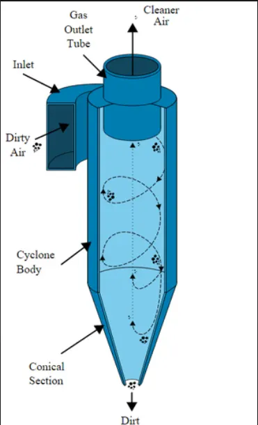
- Working of Cyclone separator:-
- Cyclone separators work much like a centrifuge, but with a continuous feed of dirty air. In a cyclone separator, dirty flue gas is fed into a chamber. The inside of the chamber creates a spiral vortex, similar to a tornado. This spiral formation and the separation is shown in Figure. The lighter components of this gas have less inertia, so it is easier for them to be influenced by the vortex and travel up it. Contrarily, larger components of particulate matter have more inertia and are not as easily influenced by the vortex.
- Since these larger particles have difficulty following the high-speed spiral motion of the gas and the vortex, the particles hit the inside walls of the container and drop down into a collection hopper. These chambers are shaped like an upside-down cone to promote the collection of these particles at the bottom of the container. The cleaned flue gas escapes out the top of the chamber.
- Most cyclones are built to control and remove particulate matter that is larger than 10 micrometers in diameter. However, there do exist high efficiency cyclones that are designed to be effective on particles as small as 2.5 micrometers.
- Efficiency of Cyclone separator:-
- Cyclone separators are generally able to remove somewhere between 50-99% of all particulate matter in flue gas. How well the cyclone separators are actually able to remove this matter depends largely on particle size.
- If there is a large amount of lighter particulate matter, less of these particles are able to be separated out. Because of this, cyclone separators work best on flue gases that contain large amounts of big particulate matter.
Empirical models used to calculate the cyclone separator efficiency :
1) lozia and Leith model:
Iozia and Leith model is modified version of Barth model. This model is developed based upon force balance. The model assumes that a particle carried by the vortex endures the influence of two forces i.e. centrifugal force and flow resistance.
Collection efficiency of a particles with diameter`d_("pi")`can be calculated as-
`eta_i=1/(1+(d_(pc)/d_("pi"))^beta)`
Where,
`beta="Expression for slope parameter"`
`beta=0.62-0.87ln(d_(pc)/100)+5.21ln((ab)/D^2)+1.05ln((ab)/D)^2`
`d_(pc)="50% cut size"`
`d_(pc)=[(9muQ)/(pirho_pz_cv_(tmax)^2)]^0.5`
2) Li and Wang model:
Li and Wang model includes particle bounce or re-entrainment and turbulent diffusion at cyclone wall. Two dimensional analytical expression of particle distribution in cyclone is obtained.
This model based on following assumption-
- The radial particle velocity and the radial concentration profile are not constant for uncollected particles within the cyclone.
- Boundary conditions with the consideration of turbulent diffusion coefficient and particle bounce re-entrainment on the cyclone wall are:
`c=c_0" at "theta=0`
`D_r(delc)/(delr)=(1-alpha)omegac" at "r=D/2`
- The tangential velocity is related to the radius of cyclone by:`uR^n = "constant"`
The collection efficiency can be formulate as-
`eta_i=1-exp{-lambdatheta_1}`
where,
`theta_1=2pi(S+L)/a`
`lambda=((1-alpha)komega_w)/(D_rr_w^n)`
3. Koch and Licht model:
Koch and Licht collection theory recognized the inherently turbulent nature of cyclones and the distribution of gas residence times within the cyclone. Koch and Licht described particle motion in the entry and collection regions with the additional following assumptions:
- The tangential velocity of a particle is equal to the tangential velocity of the gas flow, i.e. there is no slip in the tangential direction between the particle and the gas.
- The tangential velocity is related to the radius of cyclone by: `uR^n = "constant"`
The efficiency can be calculated as-
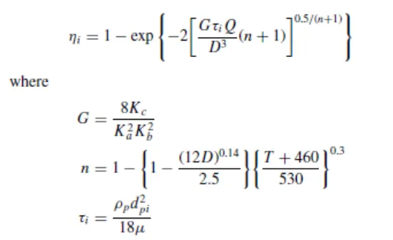
Here G is the factor related to configuration of cyclone and n is related to vortex and `tau`is the relaxation term
4. Lapple model:
Lapple model was developed based on force balance without considering the flow resistance. Lapple assumed that a particle entering the cyclone is evenly distributed across the inlet opening. The particle that travels from inlet half width to the wall in the cyclone is collected with 50% efficiency.
The semi empirical relationship developed by Lapple to calculate a 50% cut diameter, dpc, is
`d_(pc)=[(9mub)/(2piN_ev_i(rho_p-rho_g))]^0.5`
Where,
`N_e ="Number of revolution"`
`N_e=1/a[(H+h)/2]`
Thus Efficiency can be given as
`eta_i=1/(1+(d_(pc)/d_("pi"))^2)`
MODELING AND SIMULATION APPROCH:-
We are going to Study the calculate the separation efficiency and pressure drop with Different Particle Sizes and Velocities as Below.
CASE-1 :-
Particle Size is 1 micron, 3 micron and 5 micron. Velocity for Case -1 is 3 m/s.
CASE-2 :-
Particle Size is 5 micron. Velocity for case-2 is 1 m/s, 3 m/s and 5 m/s.
CASE-1 :-
I) Particle Size 1 micron and Velocity 3 m/s:-
- Geometry Preparation:-
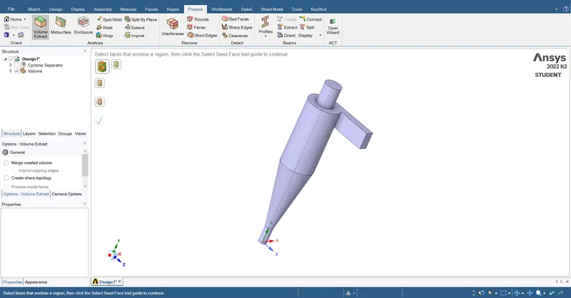
1) Import Geometry in Spaceclaim:-
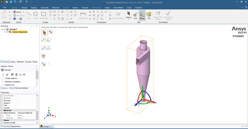
2) Volume Exract for Fluid Volume:-
For Volume Extraction step will be Prepair > Volume Extract > Select edges > Ok
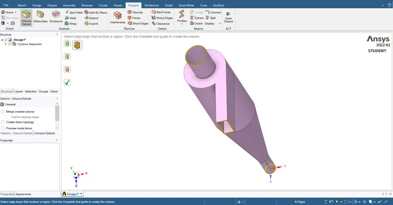
3) Supress the Unwanted Wall:-
We have to Supress the wall by Right click and Suppress for Physics after that we can get the Geometry as below:-
- Meshing:-
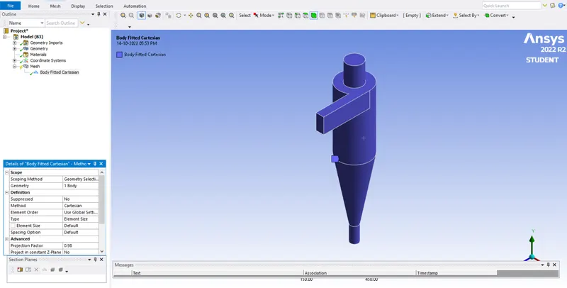
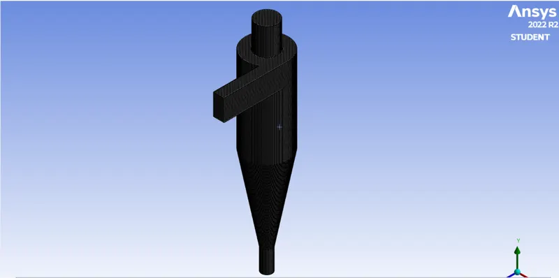
1) Open the Geometry in Ansys Meshing Interface, we are using the Cut cell Meshing (cartesian) for Maximum Particle should be track because, it is important to have equally size mesh elements within the geometry.
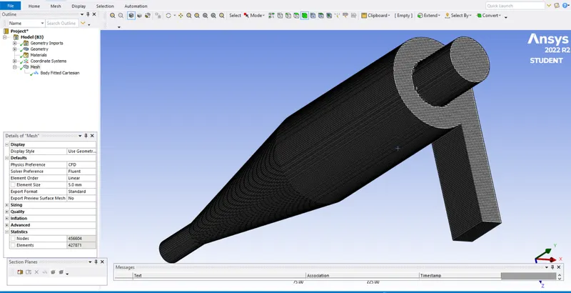
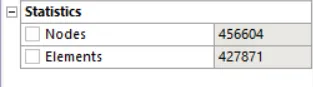
2) we are using 5 mm Element Mesh size with taking care of Ansys No. elements Restriction.
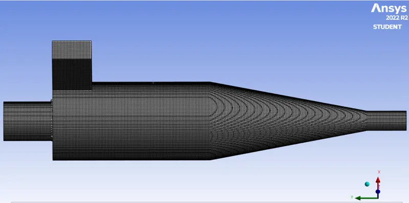
3) Final Mesh:-
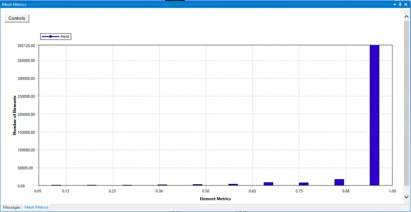
4) Element Quality:-
5) Create Named Selection:-
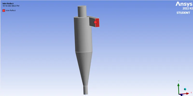
we are creating named selection as per our critera for Descret phase Modeling as below:-
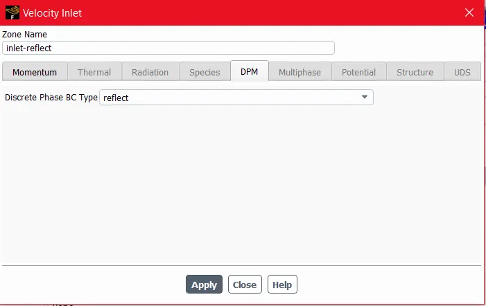
1) Inlet (Reflect):-
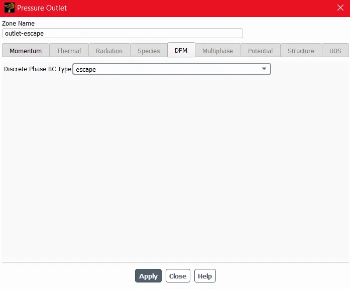
2) Outlet(Escape):-
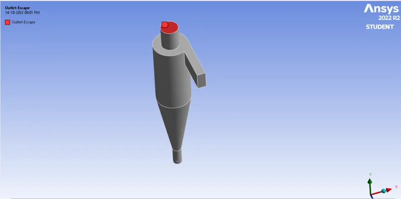
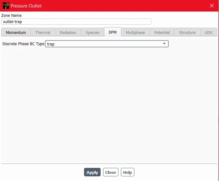
3) Outlet(Trap):-
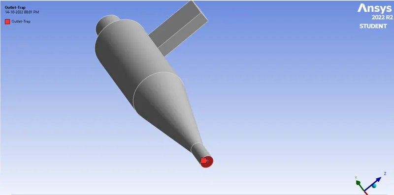
- Solver Set-up and Solution:-
| 1 | Solver | Pressure Based- Steady- Absolute |
| 2 | Gravity | ON:- -9.81 m/s^2 at Y Direction |
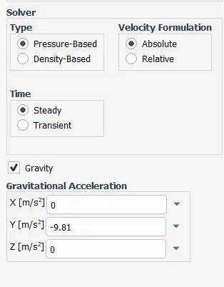
| 3 | Viscous Model | K-epsilon, RNG, Swirl Dominated Flow |
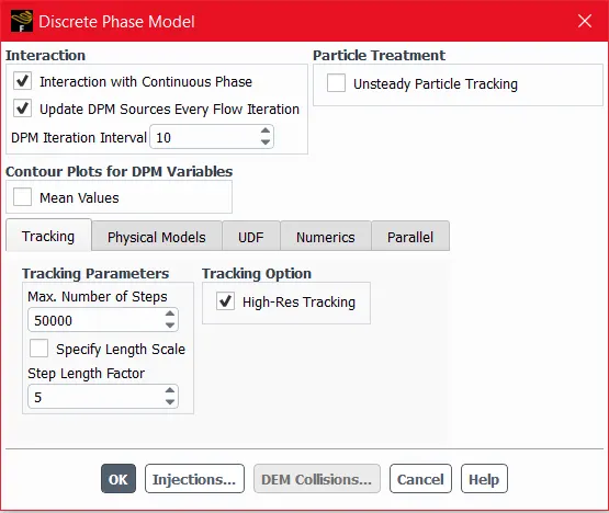
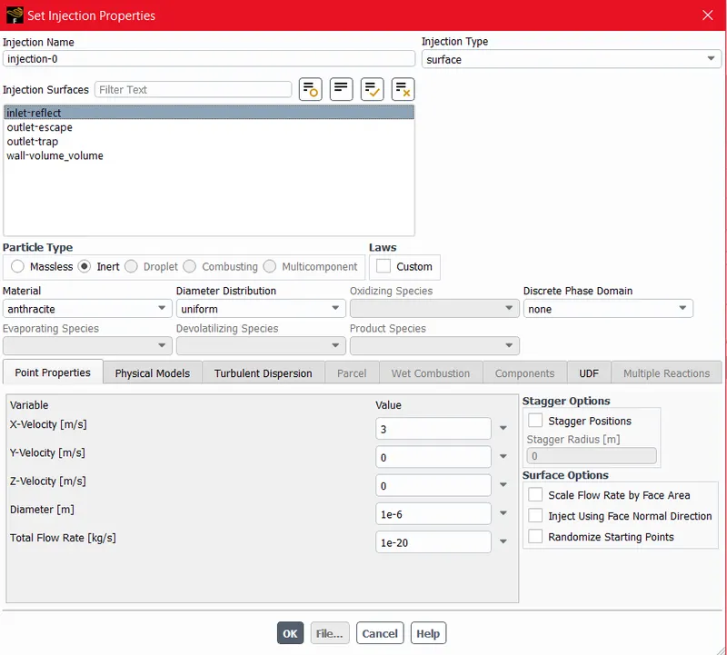
| 4 | Discrete Phase Model | ON 1) Interaction with Contineous Phase 2) Update DPM Sources 3) Surface Injection @ Inlet(Reflect) with Velocity 3 m/s. 4) Diameter of Particle 1 micron |
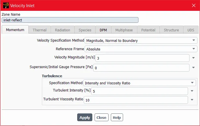
| 5 | Boundaries | 1.Inlet( Reflect) :- 3 m/s Velocity and Discrete phase BC - Reflect 2.Outlet(Escape):- Standerd Pressure Outlet with DPM -Escape 3.Outlet(Trap):- Standerd Pressure Outlet with DPM -Trap 4.Wall:- Reflect |
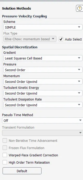
| 6 | Solution Method | SIMPLE- Second Order Upwind |
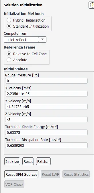
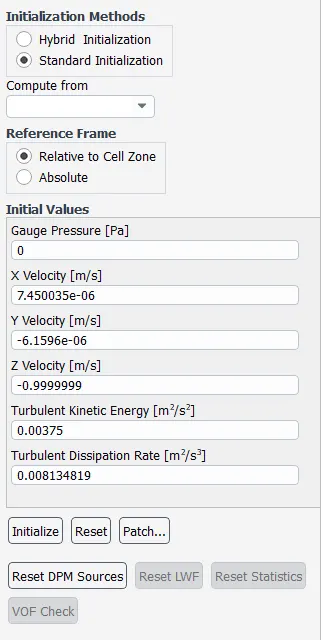
| 7 | Initialization Method | Standard Initialization- Compute from Inlet(Reflect) |
- For this perticular problem we are using Pressure based Steady type of Solver with Gravity ON with negative Y Direction.
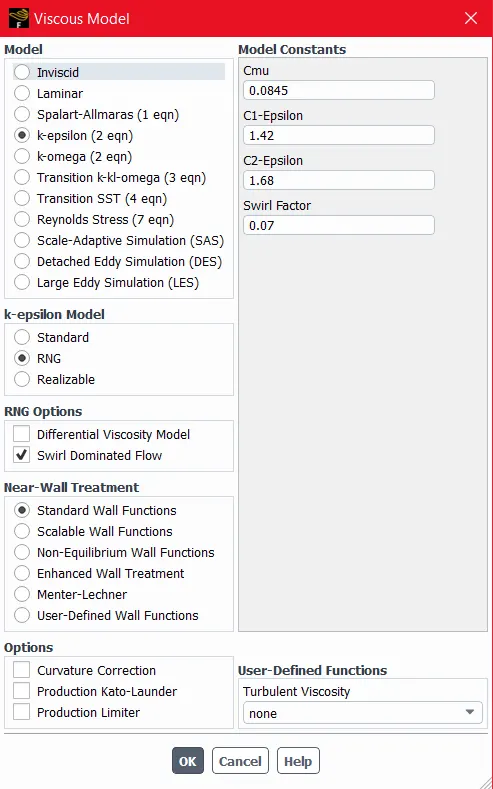
- we are using K-epsilon, RNG, Swirl Dominated Flow Viscous Model becase in this Cyclone Separator Adrupt changes in Geometry, and also we have to capture the Particles so flow might be Swirl so we are using Swirl Dominated Flow.
- Discrete Phase Model with Surface Injection @ Inlet(Reflect) with Velocity 3 m/s. and Diameter of Particle 1 micron.
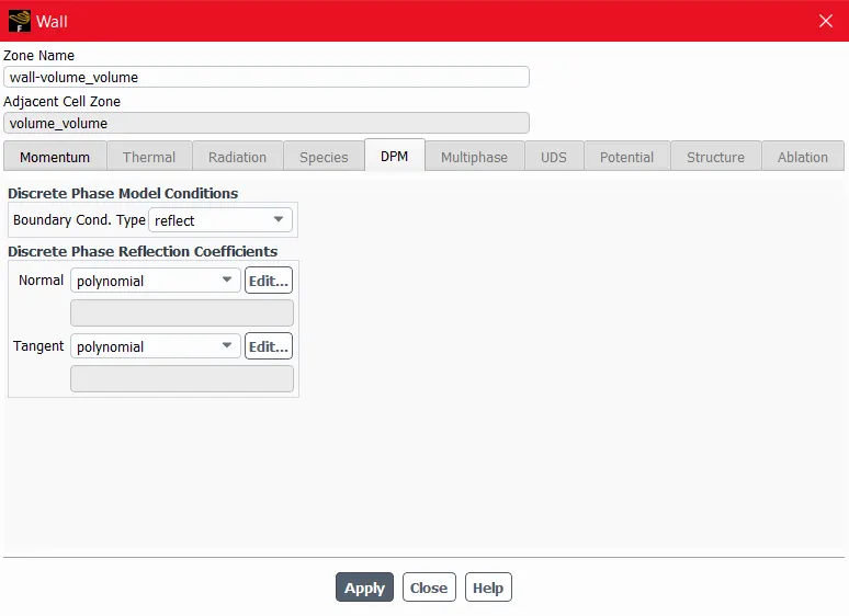
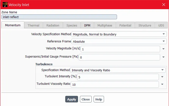
- We are Using Boundary Conditions as Below.
1) Inlet( Reflect) :- 3 m/s Velocity and Discrete phase BC - Reflect
2.Outlet(Escape):- Standerd Pressure Outlet with DPM -Escape
3.Outlet(Trap):- Standerd Pressure Outlet with DPM -Trap
4.Wall:- Reflect.
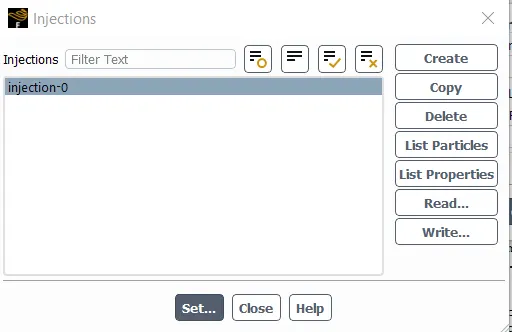
Following Snapshots for Set-up.
Viscous Model:-
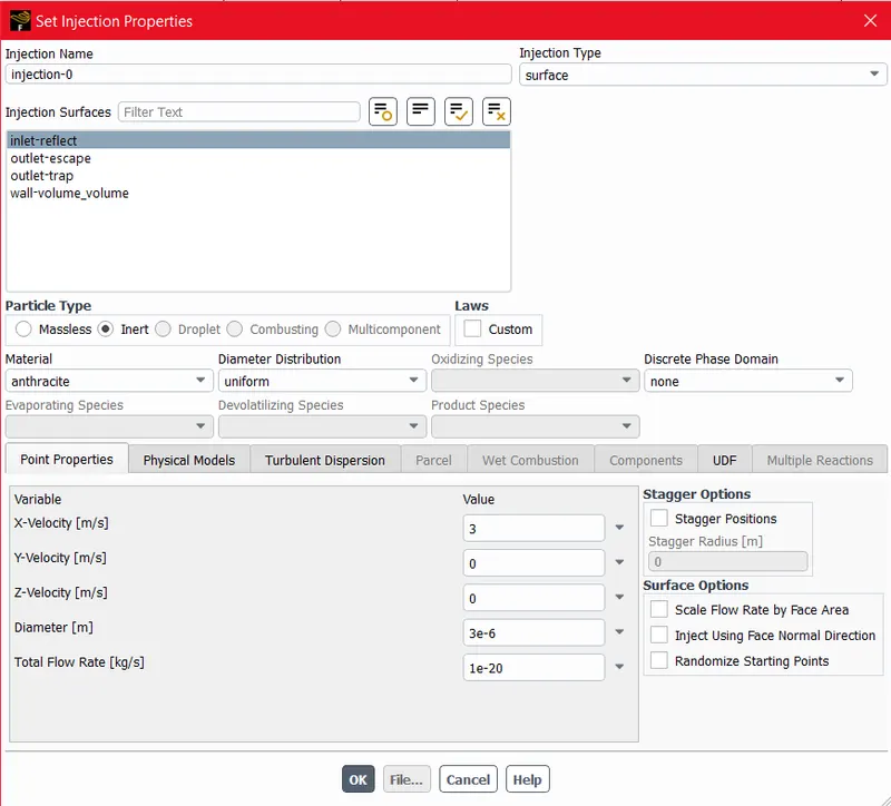
Discrete Phase Model:-
Boundary Conditions:-
Solution Method:-
RESULTS:-
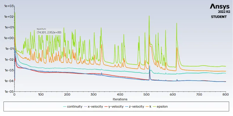
Residual Plot:-
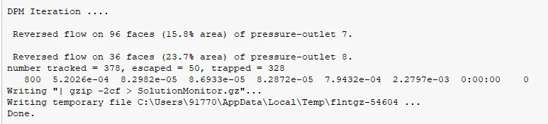
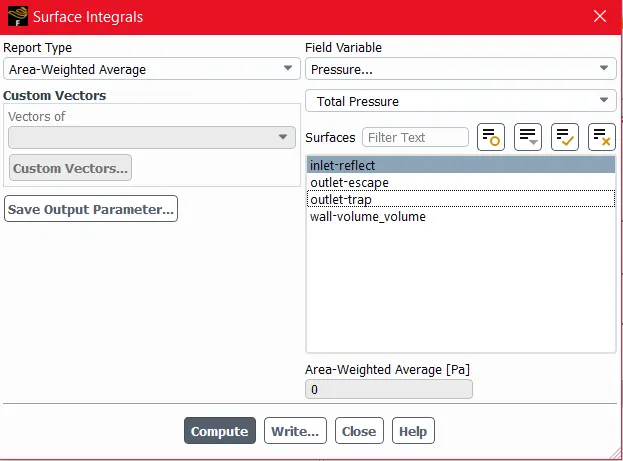
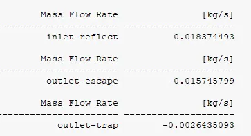
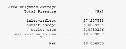
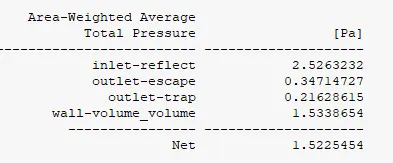
Pressure Drop:-
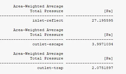
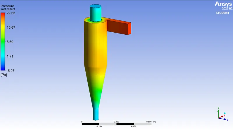
By using below Fig we can calculate the Pressure Drop
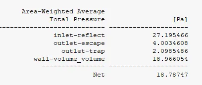
The pressure Drop is 18.78 pa.

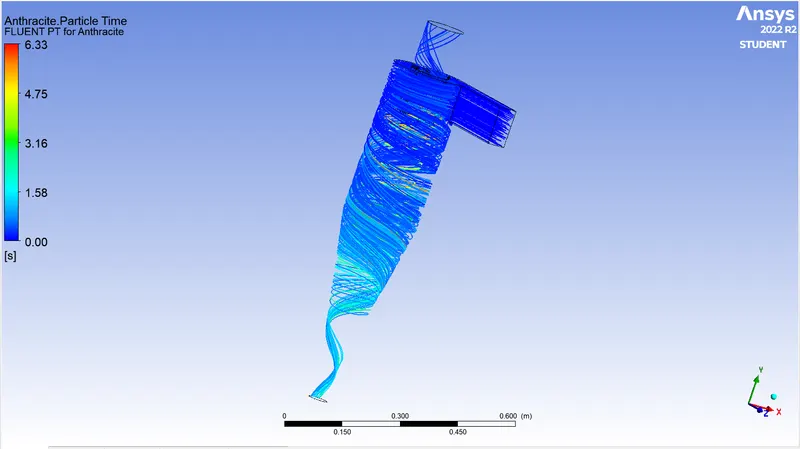
Anthracite Particle Time:-
Pressure in Cyclone Seperator:-
II) Particle Size 3 micron and Velocity 3 m/s:-
We are using Same Geometry, Mesh and Setup only particle size has been changed.
| 1 | Solver | Pressure Based- Steady- Absolute |
| 2 | Gravity | ON:- -9.81 m/s^2 at Y Direction |
| 3 | Viscous Model | K-epsilon, RNG, Swirl Dominated Flow |
| 4 | Discrete Phase Model | ON 1) Interaction with Contineous Phase 2) Update DPM Sources 3) Surface Injection @ Inlet(Reflect) with Velocity 3 m/s. 4) Diameter of Particle 3 micron |
| 5 | Boundaries | 1.Inlet( Reflect) :- 3 m/s Velocity and Discrete phase BC - Reflect 2.Outlet(Escape):- Standerd Pressure Outlet with DPM -Escape 3.Outlet(Trap):- Standerd Pressure Outlet with DPM - Trap 4.Wall:- Reflect |
| 6 | Solution Method | SIMPLE- Second Order Upwind |
| 7 | Initialization Method | Standard Initialization- Compute from Inlet(Reflect) |
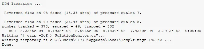
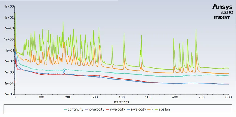
Residual Plot:-

Anthracite Particle Time:-
Pressure in Cyclone Seperator:-
III) Particle Size 5 micron Velocity 3 m/s:-
We are using Same Geometry, Mesh and Setup only particle size changed.
| 1 | Solver | Pressure Based- Steady- Absolute |
| 2 | Gravity | ON:- -9.81 m/s^2 at Y Direction |
| 3 | Viscous Model | K-epsilon, RNG, Swirl Dominated Flow |
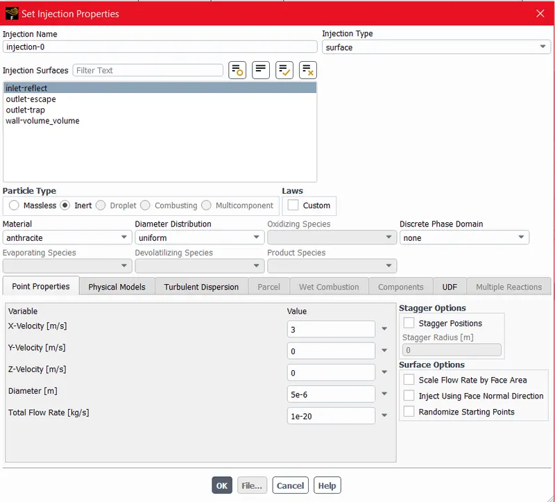
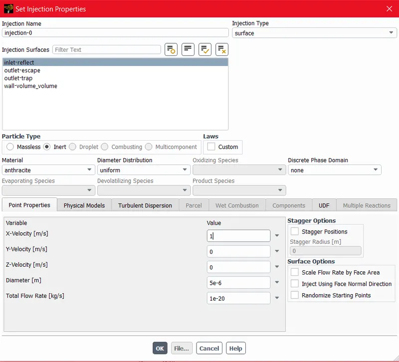
| 4 | Discrete Phase Model | ON 1) Interaction with Contineous Phase 2) Update DPM Sources 3) Surface Injection @ Inlet(Reflect) with Velocity 3 m/s. 4) Diameter of Particle 5 micron |
| 5 | Boundaries | 1.Inlet( Reflect) :- 3 m/s Velocity and Discrete phase BC - Reflect 2.Outlet(Escape):- Standerd Pressure Outlet with DPM -Escape 3.Outlet(Trap):- Standerd Pressure Outlet with DPM -Trap 4.Wall:- Reflect |
| 6 | Solution Method | SIMPLE- Second Order Upwind |
| 7 | Initialization Method | Standard Initialization- Compute from Inlet(Reflect) |
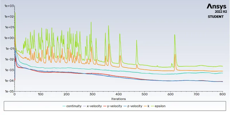
Residual Plot:-
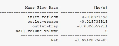

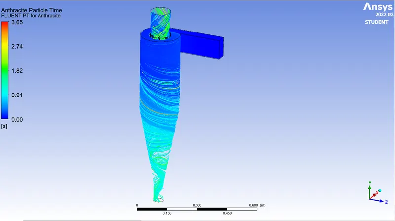
Anthracite Particle Time:-
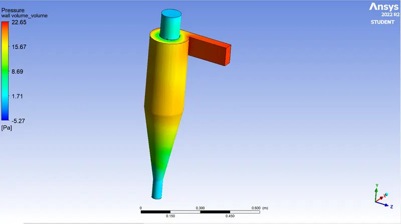
Pressure in Cyclone Seperator:-
IV) Particle Size 5 micron Velocity 1 m/s:-
We are using Same Geometry, Mesh and Setup only Velocity has been changed to 1 m/s.
| 1 | Solver | Pressure Based- Steady- Absolute |
| 2 | Gravity | ON:- -9.81 m/s^2 at Y Direction |
| 3 | Viscous Model | K-epsilon, RNG, Swirl Dominated Flow |
| 4 | Discrete Phase Model | ON 1) Interaction with Contineous Phase 2) Update DPM Sources 3) Surface Injection @ Inlet(Reflect) with Velocity 1 m/s. 4) Diameter of Particle 5 micron |
| 5 | Boundaries | 1.Inlet( Reflect) :- 1 m/s Velocity and Discrete phase BC - Reflect 2.Outlet(Escape):- Standerd Pressure Outlet with DPM -Escape 3.Outlet(Trap):- Standerd Pressure Outlet with DPM - Trap 4.Wall:- Reflect |
| 6 | Solution Method | SIMPLE- Second Order Upwind |
| 7 | Initialization Method | Standard Initialization- Compute from Inlet(Reflect) |
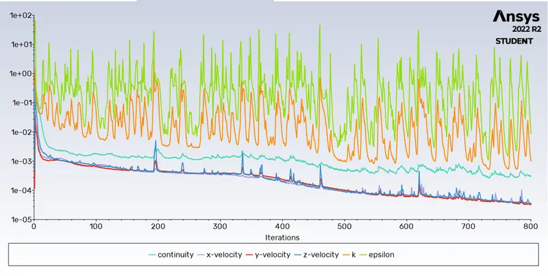
Residual Plot:-

Anthracite Particle Time:-
Pressure in Cyclone Seperator:-
V) Particle Size 5 micron Velocity 3 m/s:-
Case V Is Same as Case III so we are going to Start Case VI.
VI) Particle Size 5 micron Velocity 5 m/s:-
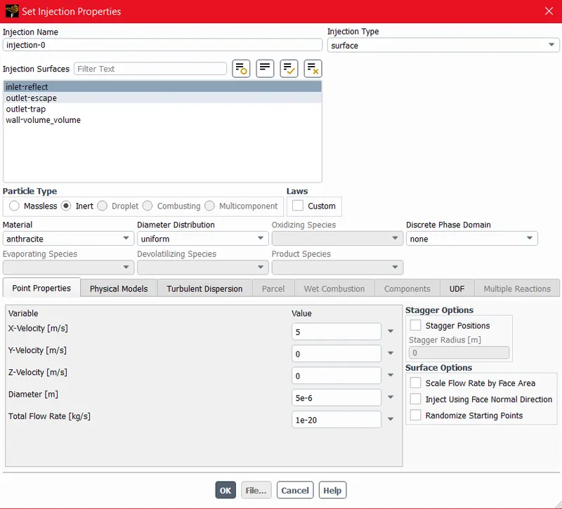
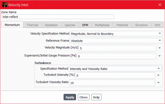
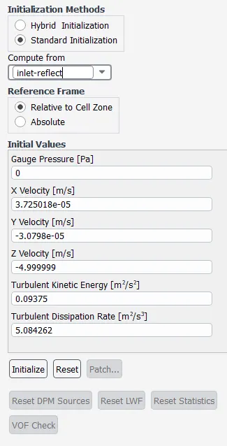
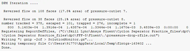
We are using the Same Geometry, Mesh and Setup only Velocity has been changed to 5 m/s.
| 1 | Solver | Pressure Based- Steady- Absolute |
| 2 | Gravity | ON:- -9.81 m/s^2 at Y Direction |
| 3 | Viscous Model | K-epsilon, RNG, Swirl Dominated Flow |
| 4 | Discrete Phase Model | ON 1) Interaction with Contineous Phase 2) Update DPM Sources 3) Surface Injection @ Inlet(Reflect) with Velocity 5 m/s. 4) Diameter of Particle 5 micron |
| 5 | Boundaries | 1.Inlet( Reflect) :- 5 m/s Velocity and Discrete phase BC - Reflect 2.Outlet(Escape):- Standerd Pressure Outlet with DPM -Escape 3.Outlet(Trap):- Standerd Pressure Outlet with DPM - Trap 4.Wall:- Reflect |
| 6 | Solution Method | SIMPLE- Second Order Upwind |
| 7 | Initialization Method | Standard Initialization- Compute from Inlet(Reflect) |
Residual Plot:-
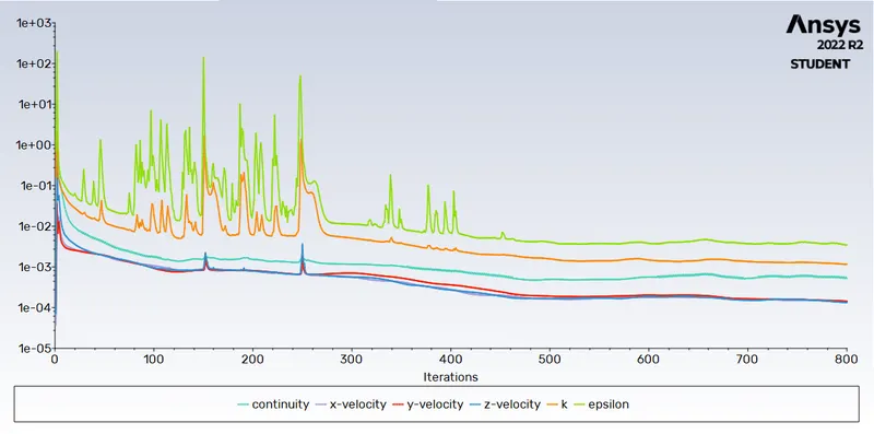
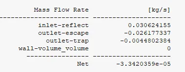
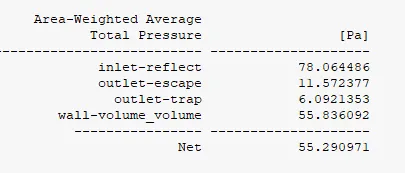

Anthracite Particle Time:-
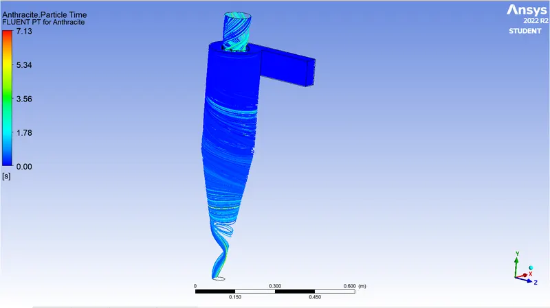
Pressure at Cyclone Seperator:-
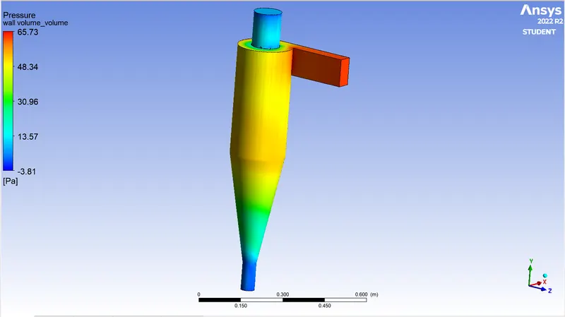
RESULT AND DISCUSSION:-
Observations Are Tabulated in Below:-
| Case-1 | Same Velocity with Different Particle Size | |||||||
| Sr No. |
Particle Size (in micron) |
Velocity of Particle and Air ( in m/s) | Particle Tracked | Particle Escaped | Particle Trapped | Incomplete | Separation Efficiency (%) | Pressure Drop (Pa) |
| 1 | 1 | 3 m/s | 378 | 50 | 328 | 0 | 86.77 | 18.78 |
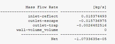
| 2 | 3 | 3 m/s | 378 | 46 | 332 | 0 | 87.83 | 18.8 |
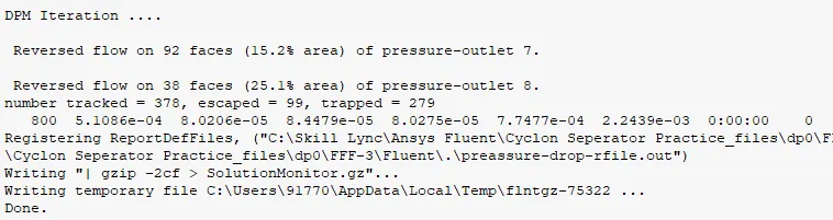
| 3 | 5 | 3 m/s | 378 | 99 | 279 | 0 | 73.81 | 18.78 |
1)From Above table we can see the Velocity of particle and air is same and in this case as Particle Size incresed The Separation Efficiency Decreased.
2) From above table we can say that Particle Tracking is Depends on the Velocity of Particle and air and Particle Size.
3) The Pressure Drop is Same as Particle Size Increased while Velocity same 3 m/s.
The Efficiency calculated from below Formula:-
Separation Efficiency (%) = `"(Number of Particles Trapped)"/"(No. of Particles Escaped From Outlet)"*100`
| Case-2 | Different Particle Size with Same Velocity | |||||||
| Sr No. | Particle Size ( in micron) |
Velocity of Particle and Air ( in m/s) | Particle Tracked | Particle Escaped | Particle Trapped | Incomplete | Separation Efficiency (%) | Pressure Drop (Pa) |
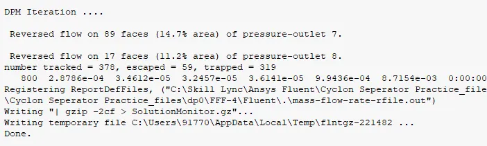
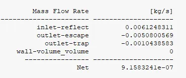
| 1 | 5 | 1 m/s | 378 | 59 | 319 | 0 | 84.39 | 1.52 |
| 2 | 5 | 3 m/s | 378 | 99 | 279 | 0 | 73.81 | 18.78 |
| 3 | 5 | 5 m/s | 378 | 101 | 276 | 1 | 73.02 | 55.29 |
1)From Above table we can see that as Velocity incresed Gradually the Seperation Efficiency decresed.
2) From above table we can say that Particle Tracking is Depends on the Velocity of Particle and air and Particle Size.
3) Pressure Drop is Increased when Velocity Increased from 1.52 pa to 55.29 pa.
CONCLUSION:-
- The separation efficiency is increasing if we increase the particle size with constant particle velocity and flow velocity.
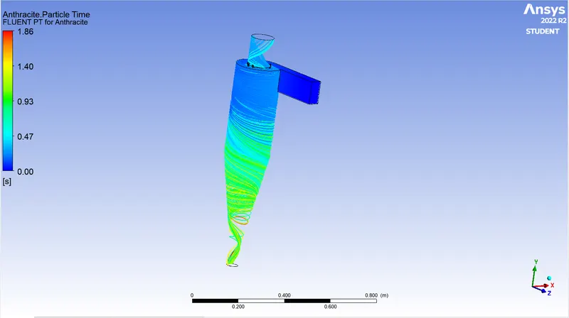
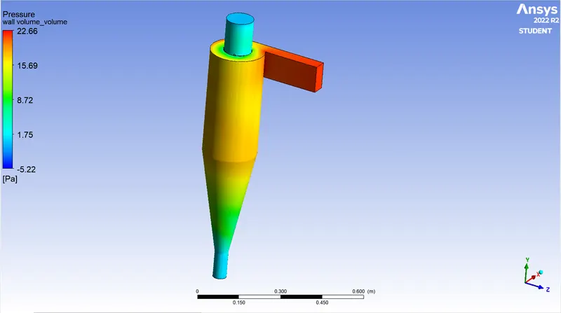
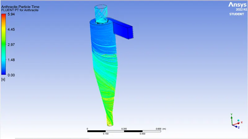
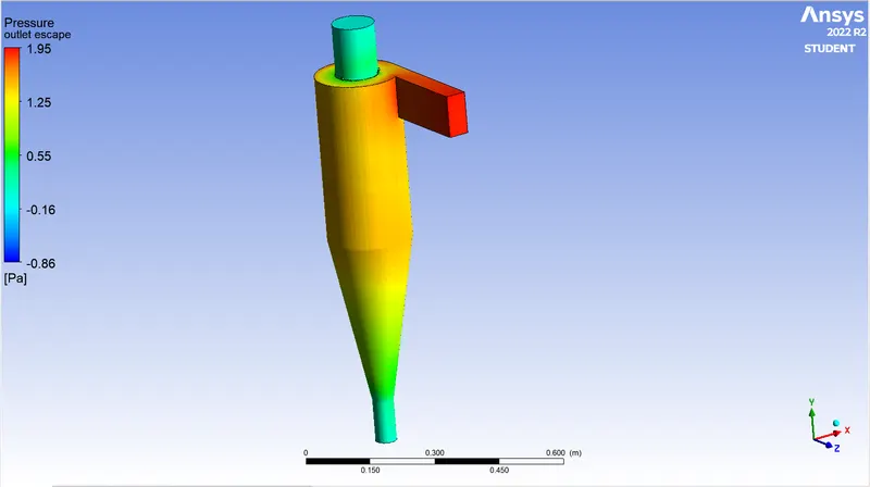
- We are Concluded The Swirling is Developed at Wall of the Cyclone Seperator from Pressure and Anthracite particle Time.
- Pressure Drop is Increased when Velocity Increased.
-
Pressure drop occurs because of the following components:
- Loss due to the expansion of gas in the cyclone chamber.
- Loss due to rotational kinetic energy.
- Loss due to wall frictional forces.
- The efficiency of the cyclone will decrease with an increase in the parameters such as gas viscosity, cyclone body diameter, gas exit diameter, gas inlet duct area, gas density, leakage of air into dust outlet. With the increase in inlet velocity or particle size the efficiency increases.