Week 3 Challenge : CFD meshing on Turbocharger
AIM:- For the given model, check for the geometrical errors to make appropriate volumes. Create and assign PIDs as shown in the video. Perform surface mesh with the given target lengths as per PIDs.
OBJECTIVE:-
Perform Surface Mesh And Volumetric mesh for the required volumes as per Given criteria as below:-
- Blade stage-1 = 1 mm
- Blade stage-2 = 1 mm
- Impeller = 2 mm
- Shaft rotor = 1 mm
- Turbo casing = 5 mm
- Compressor casing = 5 mm
- Inlet casing cover = 5 mm
THEORY:-
Accurate mesh generation is a critical step of every engineering design workflow that involves FE analyses, CFD simulations. So we need to Study the behavior of mesh on any Model to find out the Effect on Geometry.
- Surface Meshing:- Surface meshes use two-dimensional elements typically triangles or quads to approximate the outer surface of a 3D body. Surface meshes are used in manufacturing or rendering applications and CAE simulation.
- Volume Meshing:- Volume meshes, also known as solid meshes, use three-dimensional elements typically tetrahedrons, hexahedrons, and polyhedrons to define both the surface and interior structure. Surface meshes can be converted into volume meshes to run CFD simulations.
PROCEDURE:-
- IMPORT GEOMETRY:-
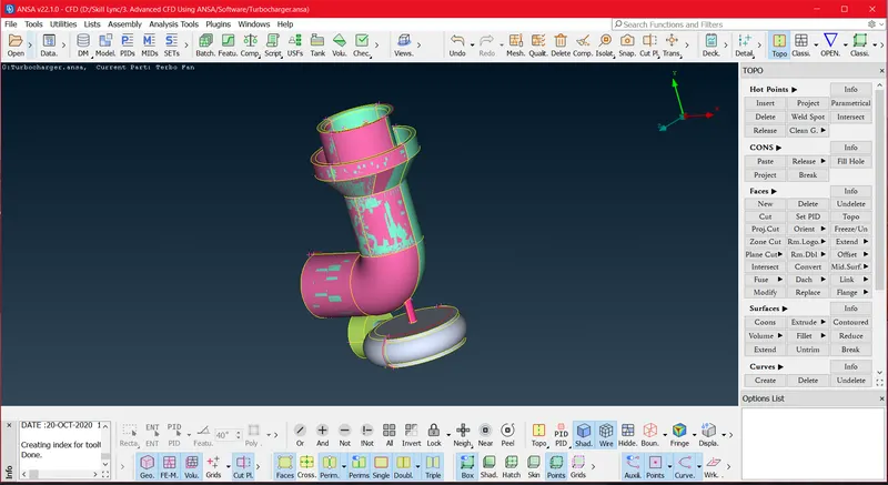
Fig. 1 Imported Geometry
- Geometry Checks and Topology cleanup:-
Imported geometry need some Topology Cleanup, we can Check Geometry Errors and Topology Cleanup. because Geometry having Uneven Surfaces, Holes, Overlapping Surfaces as shown in above Fig.
So we can starts with Geometry Checks.
Checks > Check Manager > Geometry_checks > Execute
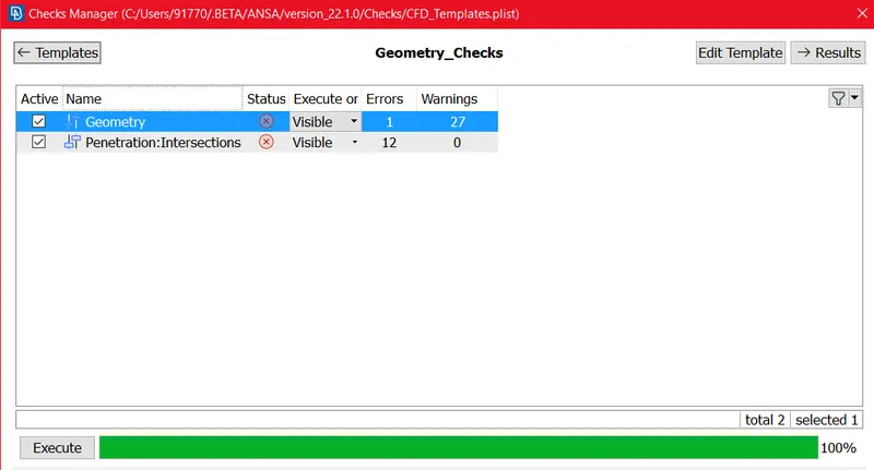
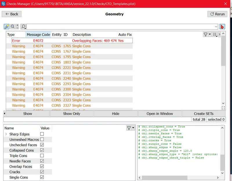
Fig. 2 Geometry Checks
Now we have to Clear those errors and Intersected Surfaces Clean.
First of all we can use Project > Cons Option and Project the Unwanted surface con on neghouring surface, then we can delete the Unwanted part by using Universal delete option. then we can get Cleaned Surface as shown Fig. 4
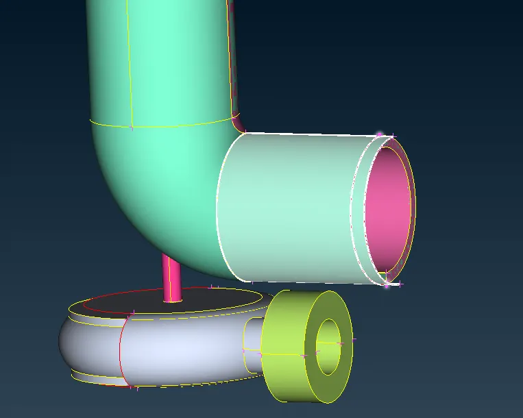
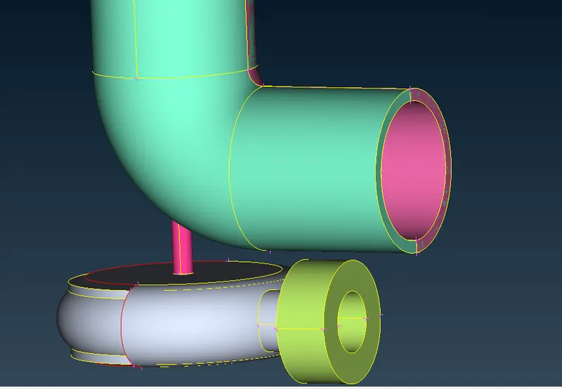
Fig. 3 Unwanted Surface Fig. 4 Cleaned Surface
Then we can Delete the Unwanted Overlaping Surface from PID's becase Overlaping Surface itself a PID, so we can delete the Pink color PID, then we can get Cleaned Surface as below Fig. 6
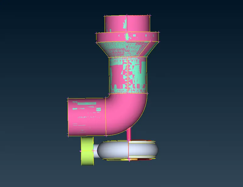
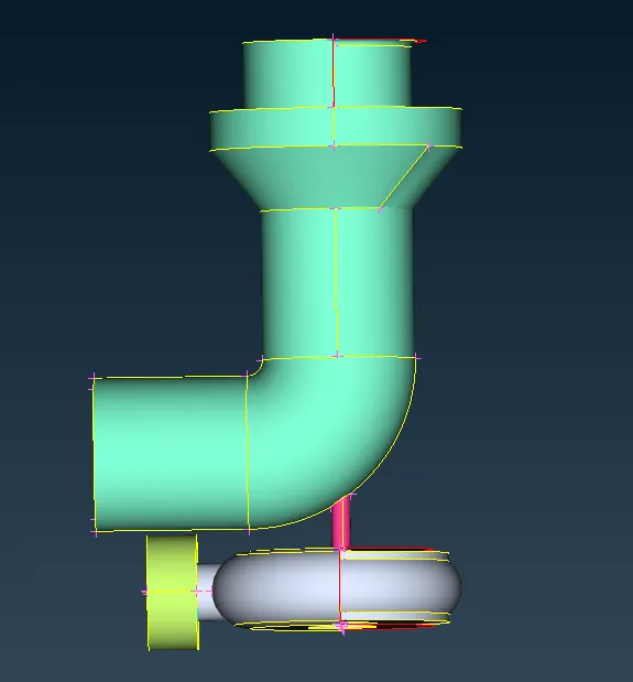
Fig.6 Overlaping Surface Fig.7 Cleaned Surface
Then we can Resolve the Opening Surface by using Transform Function Transform > Entities > select Entity > Mirror 3 point plane > Select 3 points > Ok as We have symmetry Surface.
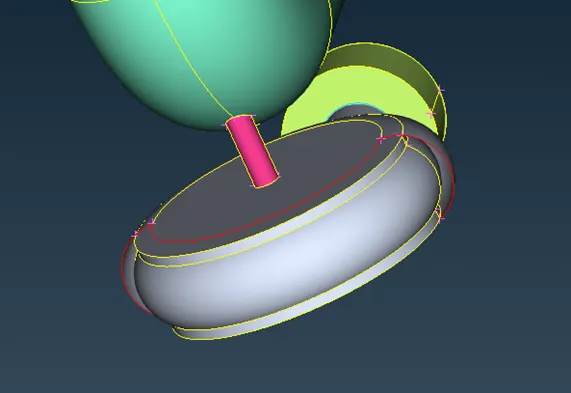
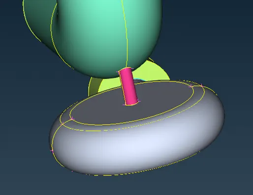
Fig. 8 Opening at surface Fig.9 Cleaned Surface
Then we can Resolve the Opening Surface by using New > coons > Select Coons > Surface Preview > Middle click Then we can get Cleaned Surface.
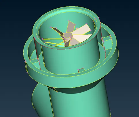
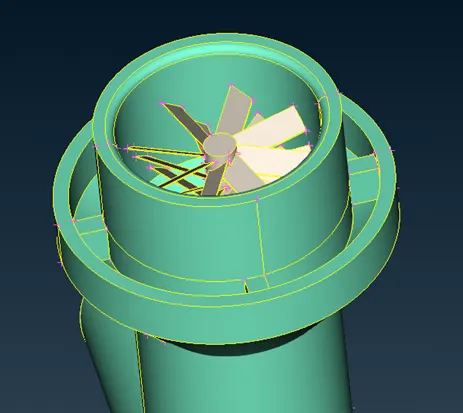
Fig. 10 Opening at surface Fig.11 Cleaned Surface
Then we can Resolve the Un-even surface at Cone By deleting The surfaces and creating again.
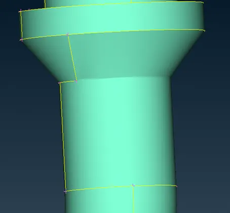
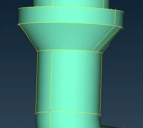
Fig. 12 Un-even Surface Fig. 13 Cleaned Surface
Then we have to delete the Un wanted Faces in The roter Shaft. Then we have to clear the interference (overlaping Surface)
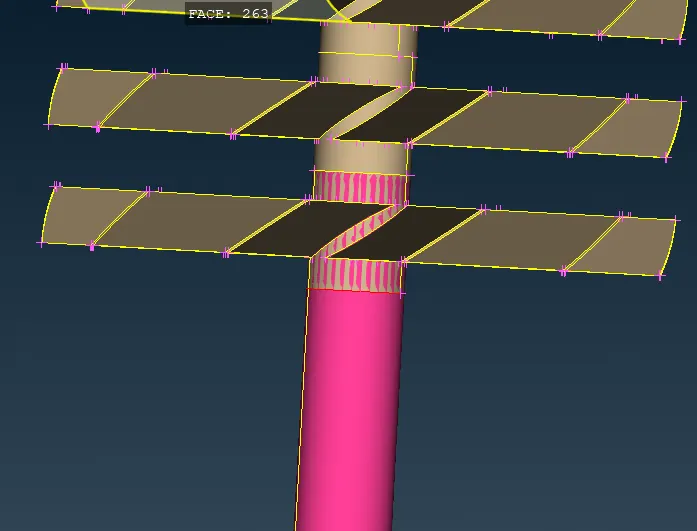
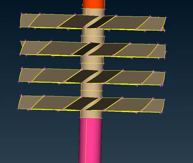
Fig. 14 Overlapped Surface Fig. 15 Cleaned Surface
Then here in between blade and Shaft having triple cone means having intersection there so we can fix by using Project Cones.
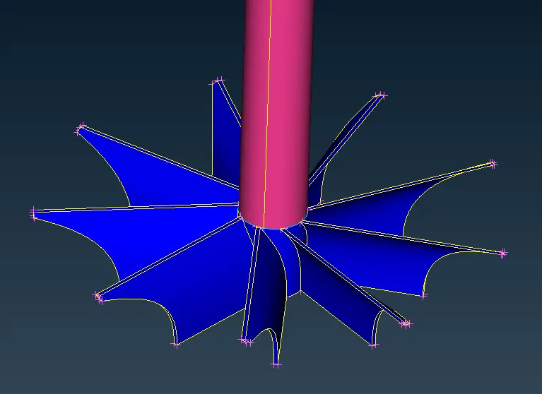
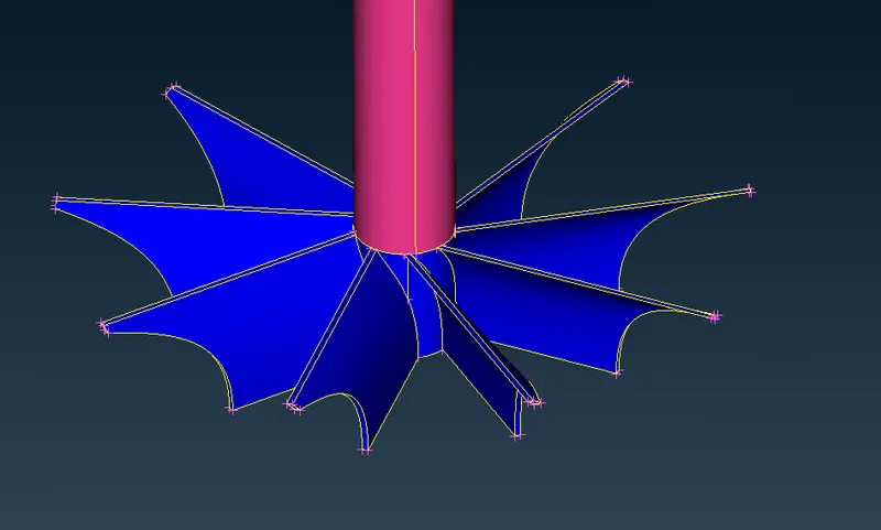
Fig. 16 interdsection Surface Fig. 17 Cleaned Surface
Still These Intersection Errors are pending, so we can try to overcome.
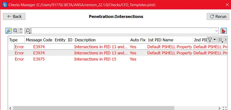
Fig. 18 Intersection Errors
Then try out to Overcome the Inter section errors, in below fig we can see overlapped surface is there by deleting overlapped surface we can get cleaned surface.
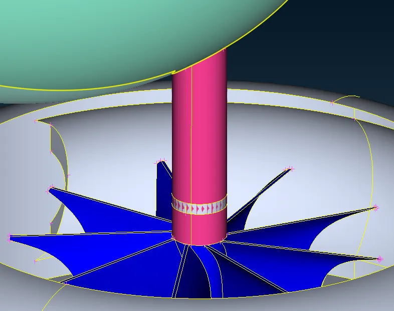
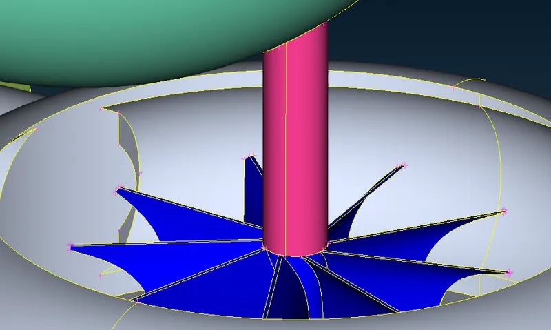
Fig. 19 Overlapped Surface Fig. 20 Cleaned Surface
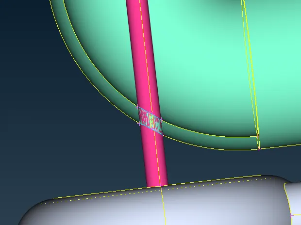
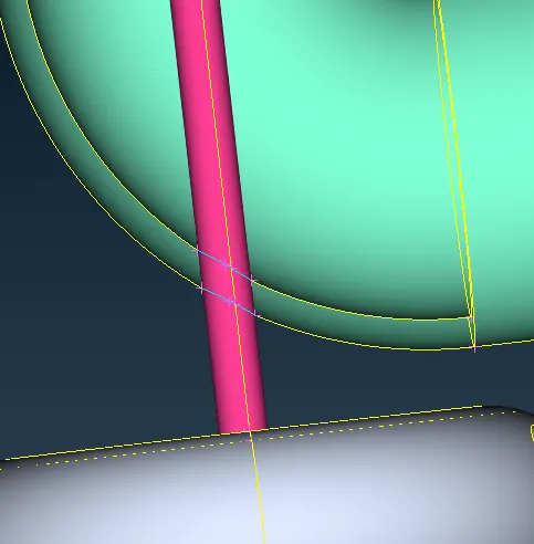
Fig. 21 Overlapped Surface Fig. 22 Cleaned Surface
Still one Intersection error Pending, deleting surface and creating again we can get Error free.
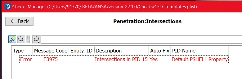
Then We can fill the All Opening so we can go to Correct Volume.
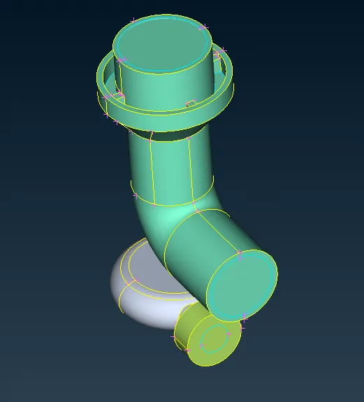
Again We have to check the Geometry And Intersection Error.
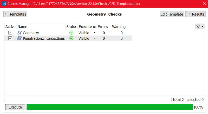
After Clearing All the Errors next we have to ASSIGN the PID's as per geometry.
- ASSIGN PID's:-
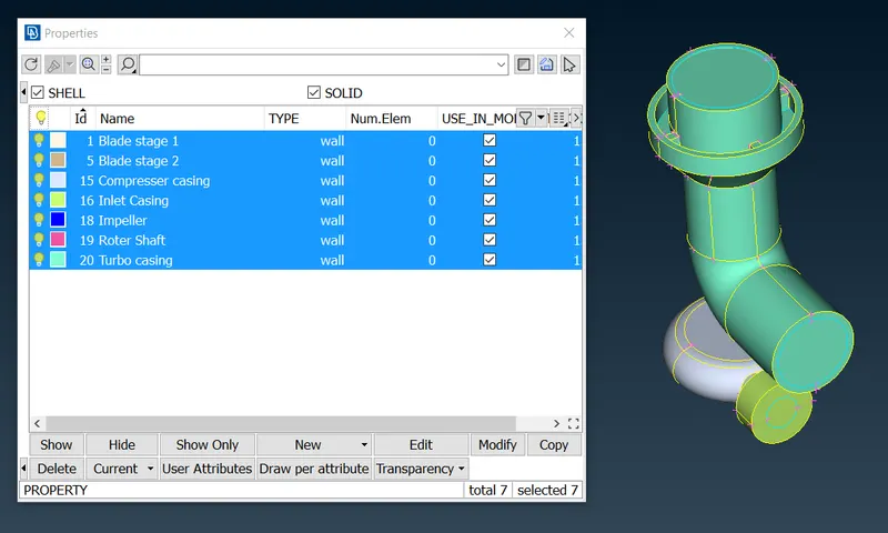
After ASSIGNING PID's We can start to Surface Meshing.
- Surface Meshing:-(1) In Problem given The Mesh Size for Surface Meshing Blade stage-1 = 1 mm, Blade stage-2 = 1 mm and Shaft rotor = 1 mm. so we can start meshing as per PID's.
Mesh Parameter for Blade stage 1, Blade stage 2 and Shaft Rotor:-
Select PID > Mesh Parameter > Mesh Quality Criteria > Length Parameter > CFD Mesh
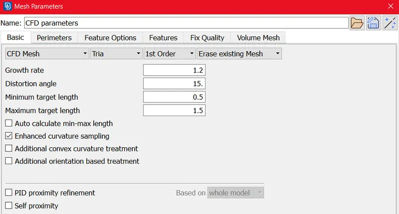
Mesh Quality Criteria for Blade stage 1, Blade stage 2 and Shaft Rotor:-
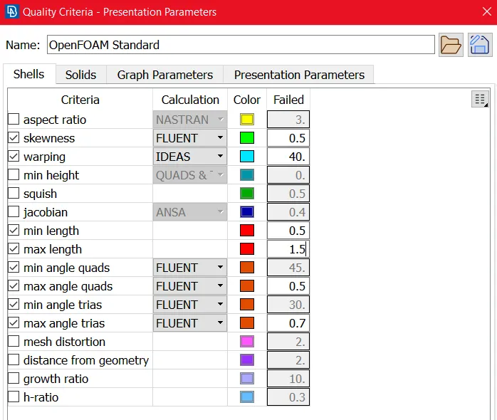
Length Parameter for Perimeter and macros :-
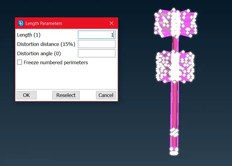
CFD SURFACE MESH for Blade Stage and Rotor Shaft :-
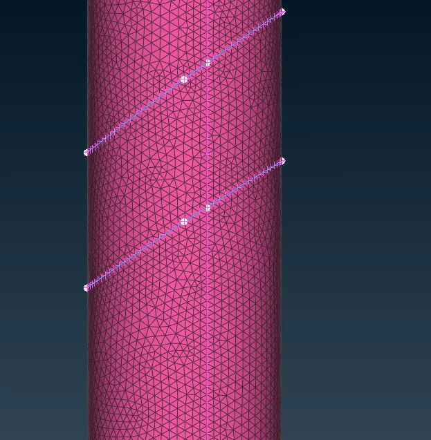
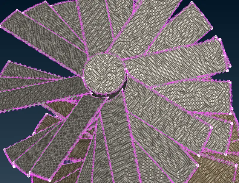
Mesh Element size for Blade stage 1, Blade stage 2 and Shaft Rotor:-
Mesh Element size is 558249
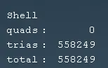
After Performing mesh Freeze these PID's (Blade stage 1, Blade stage 2 and Rotor Shaft).
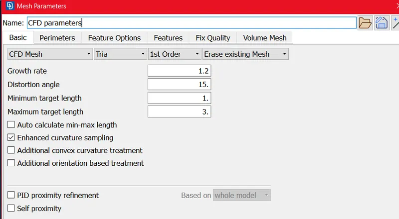
(2) In Problem given The Mesh Size for Surface Meshing Impeller = 2 mm so we can start meshing as per PID's.
Select PID > Mesh Parameter > Mesh Quality Criteria > Length Parameter > CFD Mesh
Mesh Parameter for Impeller = 2 mm:-
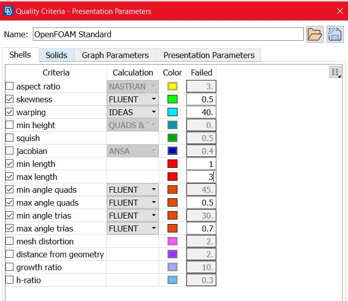
Mesh Quality Criteria for Impeller = 2 mm:-
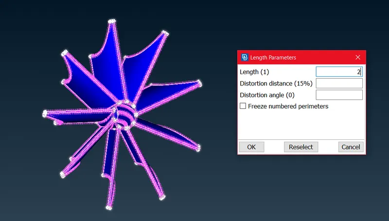
Length Parameter for Perimeter and macros :-
Generated Mesh :-
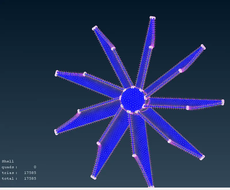
Mesh Element size is about 17585
(3) In Problem given The Mesh Size for Surface Meshing Turbo casing = 5 mm, Compressor casing = 5 mm and Inlet casing cover = 5 mm.
so we can start meshing as per PID's.
Select PID > Mesh Parameter > Mesh Quality Criteria > Length Parameter > CFD Mesh
Mesh Parameter for Turbo casing = 5 mm, Compressor casing = 5 mm and Inlet casing cover = 5 mm.:-
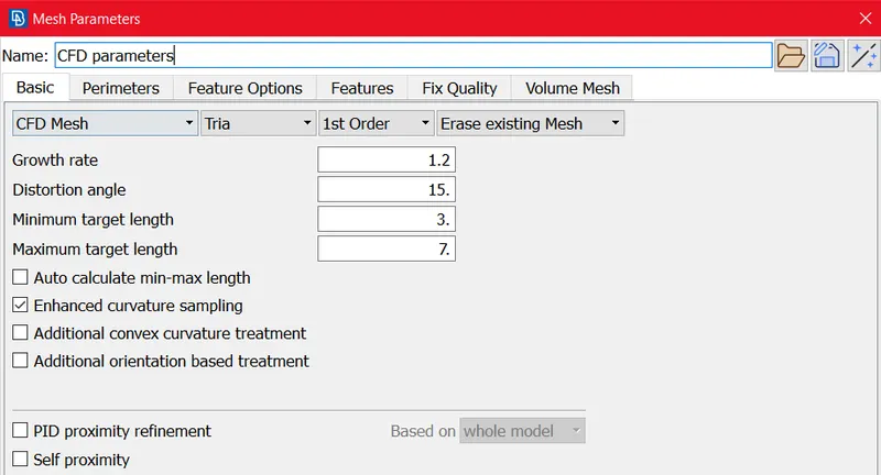
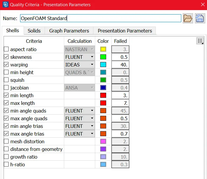
Mesh Quality Criteria for Turbo casing = 5 mm, Compressor casing = 5 mm and Inlet casing cover = 5 mm.:-
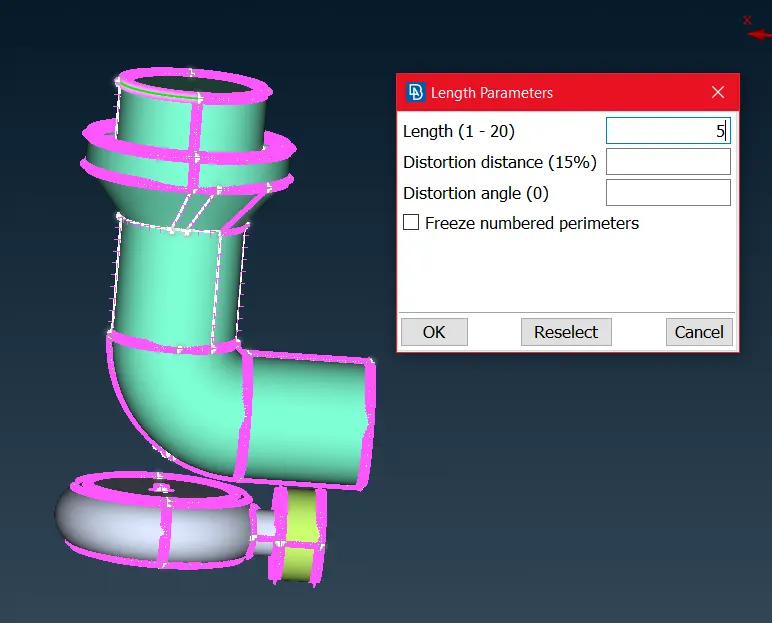
Length Parameter for Perimeter and macros :-
Generated Mesh:-
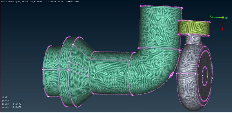
Mesh Element size is about 143670.
Total Model Surface Mesh:-
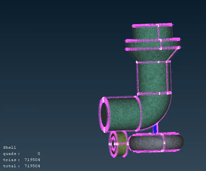
Total Mesh Element size by Surface Mesh is about 719504.
Here Surface Meshing is Completed, Now we can Start Volume Meshing.
- VOLUME MESHING:-
1. VOLUME MESH>Volumes>Define
Function Name : Define [Auto Detect]
Summary :
This function automatically defines multiple volumes using already meshed macros or FE-model mesh.
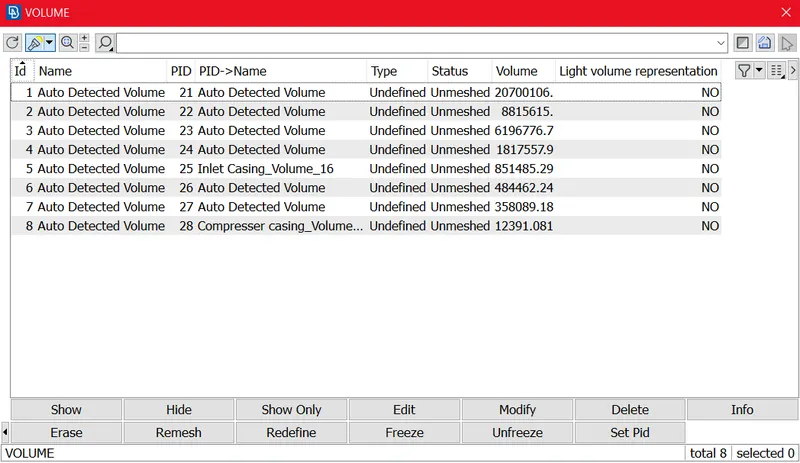
As we can see In above Fig Auto detect Volume Are generated, but we want only FLUED Flow volume, So we can delete Un-wanted PID's.
After Deleting Un-wanted PID's we are getting Volume PID's as below, then we can change The PID Type to Tetra CFD because we are using CFD Mesh
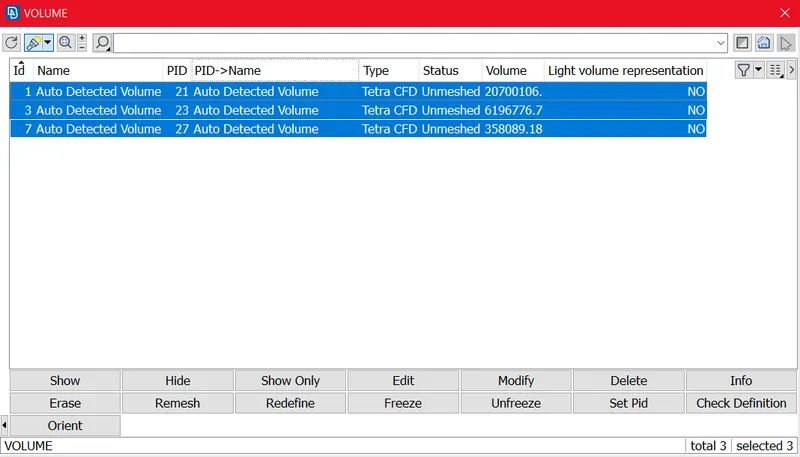
For Mesh Generation we can select all Three PID and use Remesh Option.
GENERATED VOLUME MESH:-
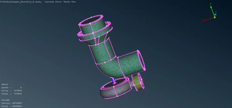
CUT-SECTION of Volume Meshing:-
By using Cut-plane we can Visuvlize The Volume Mesh.
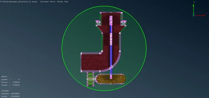
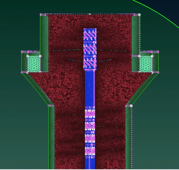
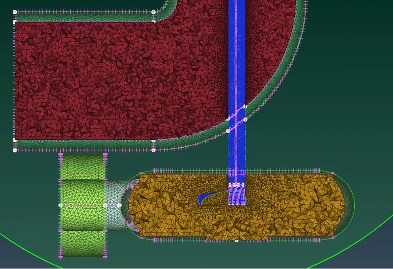
Total Mesh Element size by Volume mesh is about 6096489.
CONCLUSION:-
1. Geometry Checks, Tolpology Cleanup, Assigning PID's, Surface Mesh and Volume Mesh as per given Mesh Criteria Blade stage-1 = 1 mm, Blade stage-2 = 1 mm, Impeller = 2 mm, Shaft rotor = 1 mm Turbo casing = 5 mm, Compressor casing = 5 mm And Inlet casing cover = 5 mm has been Done for The given Turbocharger Model.
2. Total Mesh Element size by Surface Mesh is about 719504 and by Volume mesh is about 6096489.
GOOGLE DRIVE link:-
https://drive.google.com/file/d/1d_anMYmNQFFQ--dlQKOQIt-u7xHXYZ4D/view?usp=sharing