Week 11 - Final project
Objective:
To create a CAD model of Door Trim Panel with attachment features considering the given inputs, design rules and following the OEM standards.
This Project explain in brief regarding the Design life cycle followed in automotive industry by working on Practical Model car interior door trim which is a Car interior trim Part.In this Report we have explain about the steps followed to create a solid body taking Class A Surface as Input and Creating a Tooling axis and B surface with resect to the Class A Surface and Creation of Class C Surface and also the Draft Analysis.The attachment features also designed and reported as per given master section considering all the design rules for the creation of ribs and doghouse.
Given plastic class A surface
Arm rest
Map pocket
Lower map pocket
Lower substarate
Arm rest
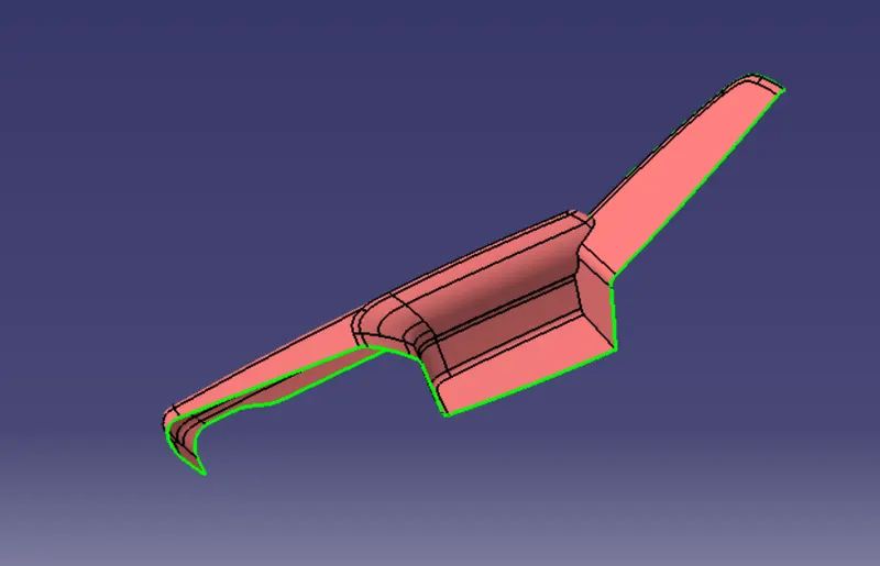
To create the surfaces and forming a close body similar we have to create the tooling axis. But to create a proper tooling axis for Arm Rest
we need to adjust the tooling axis since this component cannot be cleared in 90 deg to any (X, Y & Z) of the directions.
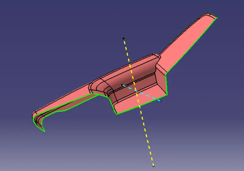
For the Arm Rest Lower Part, a side core axis is also required along with the main tooling axis.
CLASS A SURFACE
TOOLING AXIS.
in this case the main tooling axis doesent clear the all faces of the part. so we need sliding axis for clear the pocket area in door arm rest
DRAFT ANALYSIS
CLASS B SURFACE
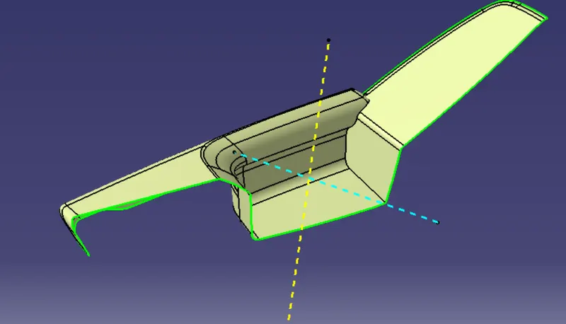
Class C surface
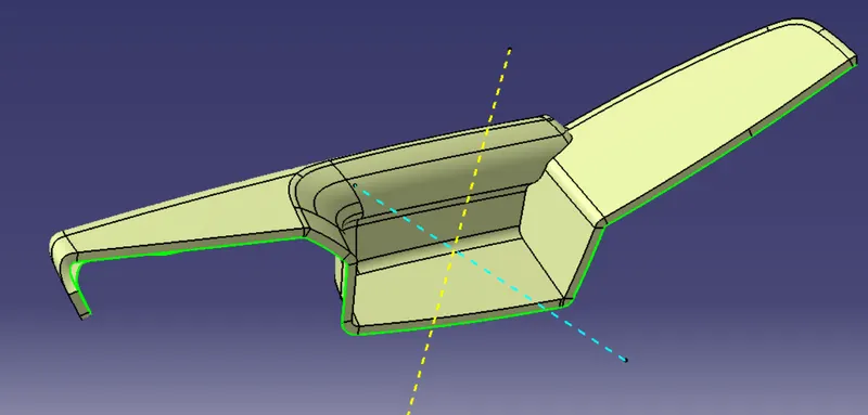
Solid body
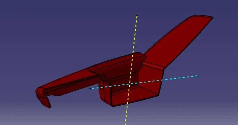
Attachment Features
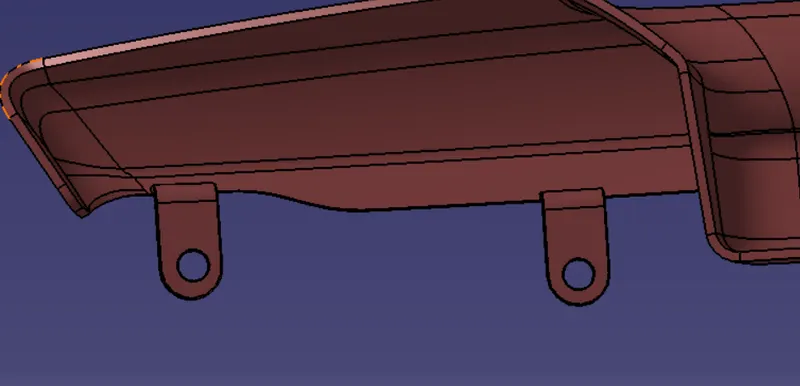
Heat stakes are used to join two or more parts that are made of plastic with the help of the heat staking process. The heat staking process involves the deformation of the plastic material using heat and force to fix it with the other parts.
To create the Heat Stake, we need to create a sketch with a circle of diameter 8mm. Now extrude this sketch to a height such that it is passing through the Flange. Using the shell option, thicken this extrude (thickness 2mm) to form a solid and give it a draft of 0.5 deg.these heat stakes are designed as per the design rules.
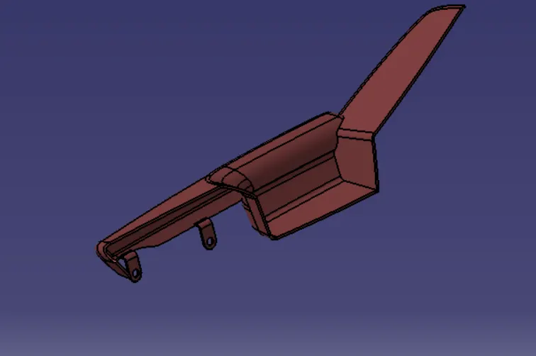
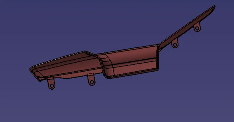
Map Pocket
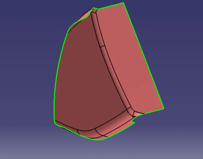
Class A surface is given as input to create the solid body
Class A surface
Tooling axis
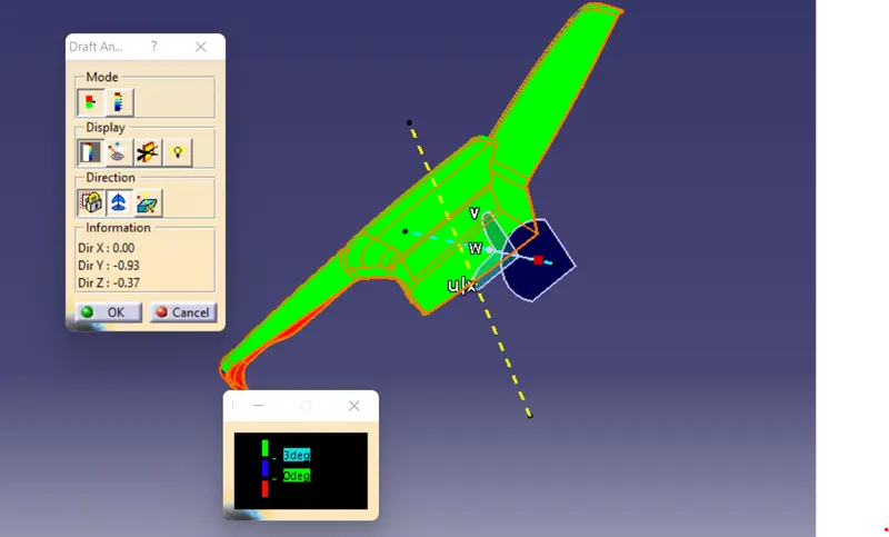
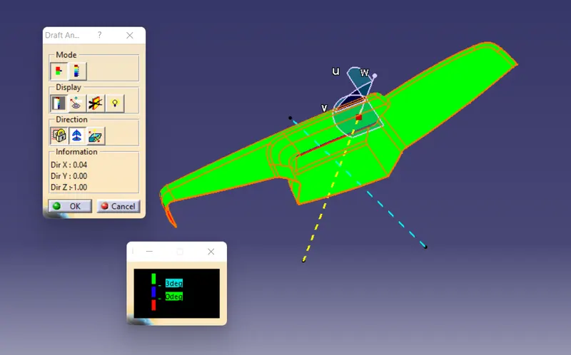
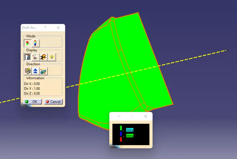
Form the visual analysis we can say that the part can be cleared from the axis normal the suraface
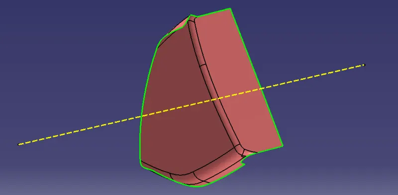
Draft analyis of class A surface
CLass B surface
By offsetting the class A surface by 2.5 mm which we got from master section class B surface is created
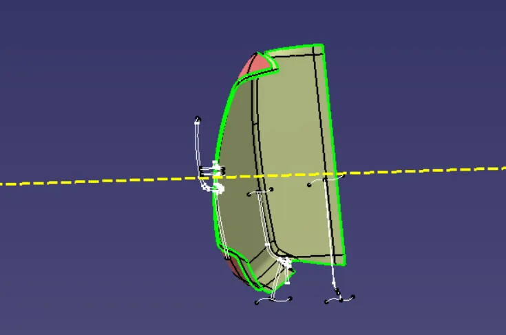
Class C surface
Create the class C surface using class A surface kepping positive draft and join with class A surface to get closed body
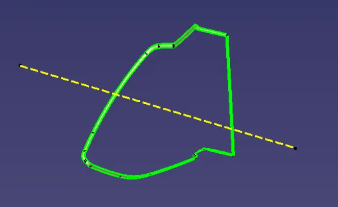
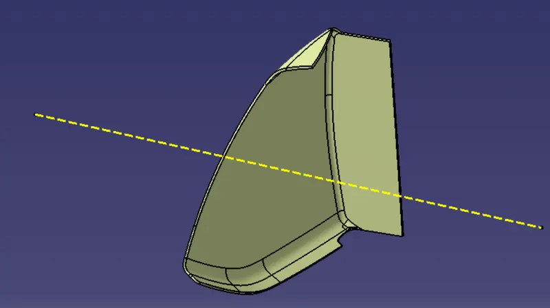
Solid Body
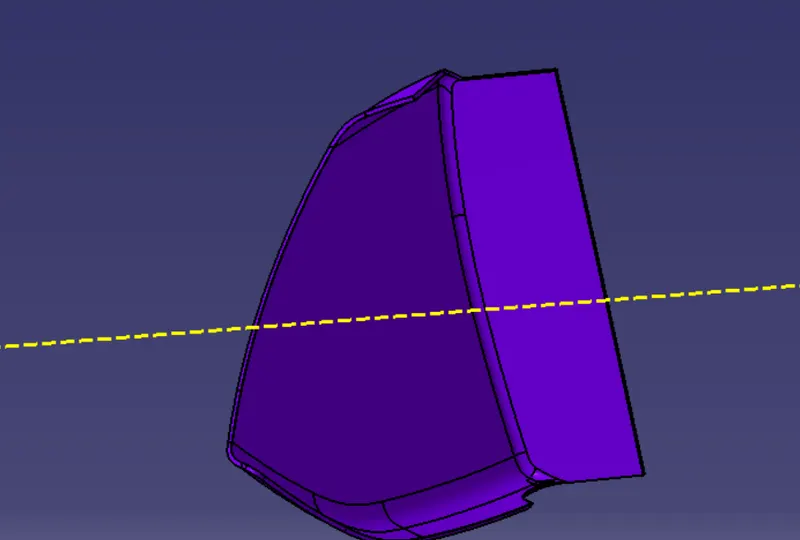
Flanges
Create the flanges to join with the other parts by considering the design standards
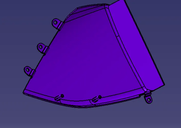
Draft analysis
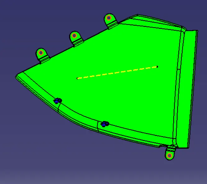
Lower Map Pocket
Class A surface is given as input to create the solid body
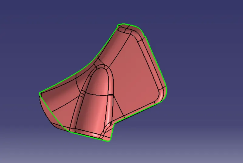
Tooling axis
Form the visual analysis we can say that the part can be cleared from the axis normal the suraface
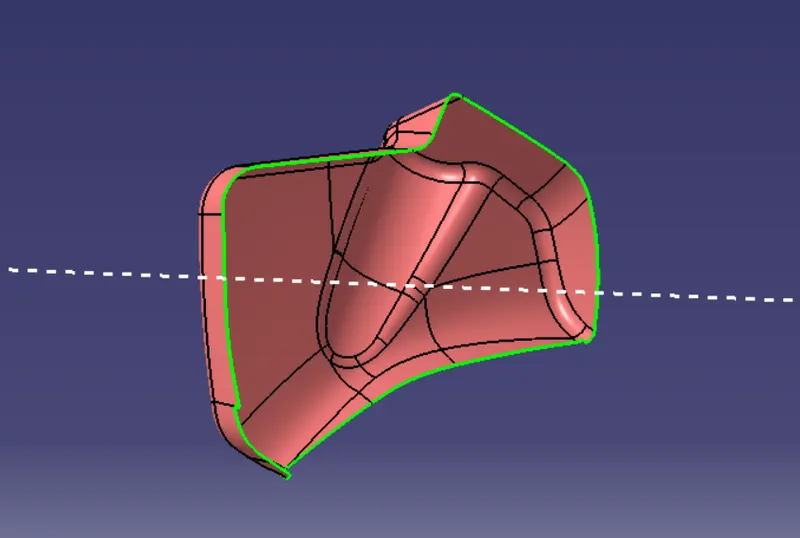
Class B surface
By offsetting the class A surface by 2.5 mm which we got from master section class B surface is created
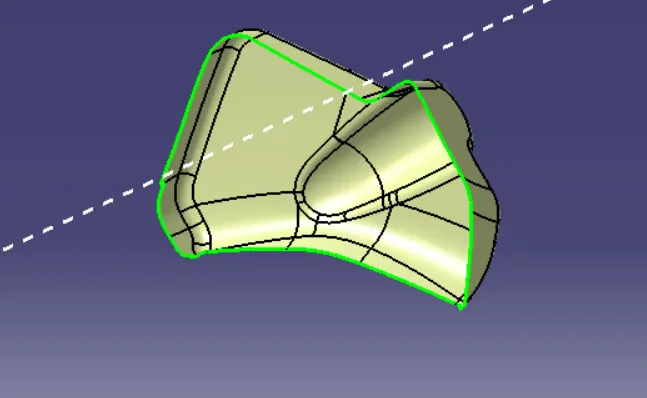
Class C surface
Create the class C surface using class A surface kepping positive draft and join with class A surface to get closed body
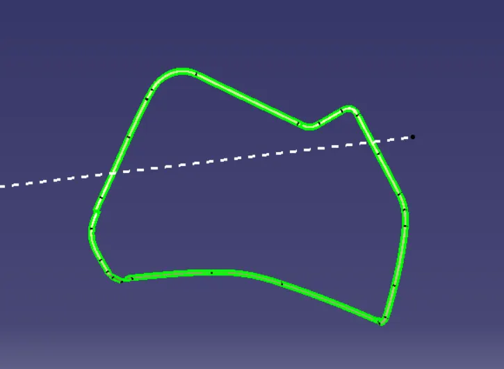
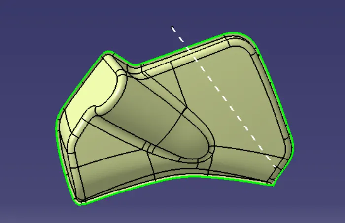
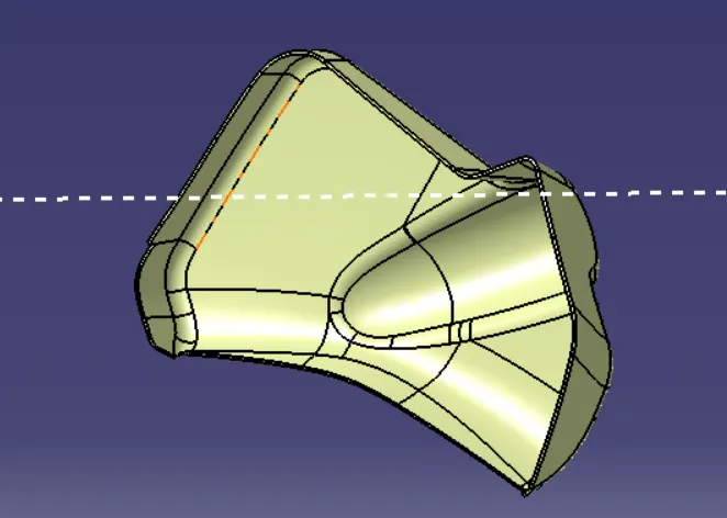
Solid Body
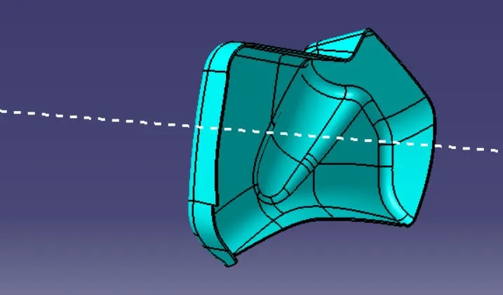
Flanges
Create the flanges to join with the other parts by considering the design standards
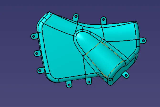
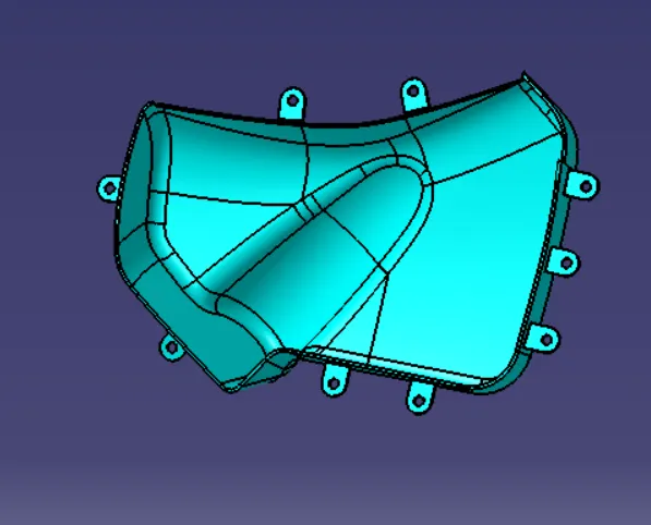
Draft analysis
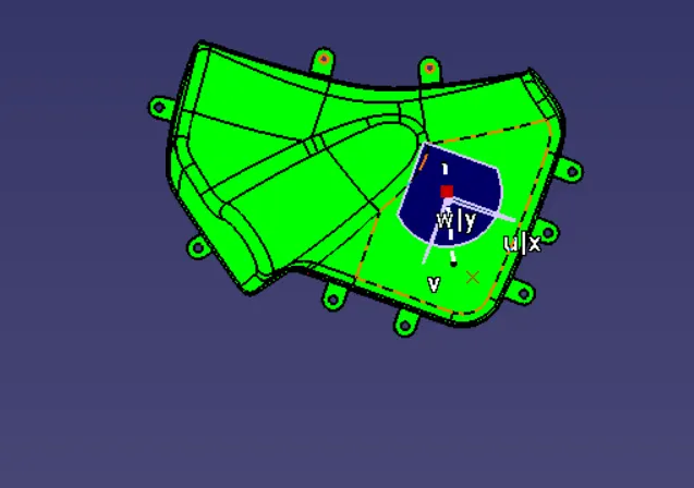
Lower substrate
Class A surface is given as input to create the solid body
Class A surface
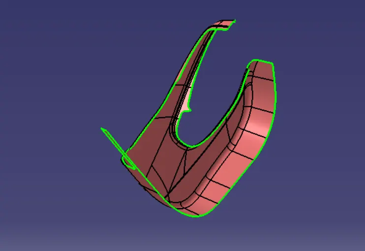
Tooling axis
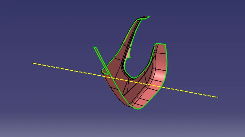
Class B surface
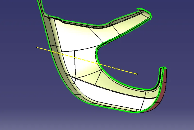
Class C surface
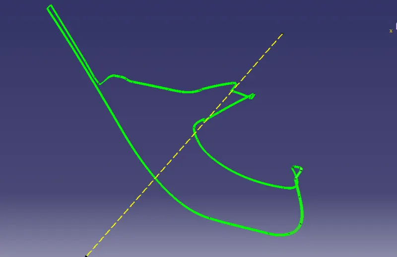
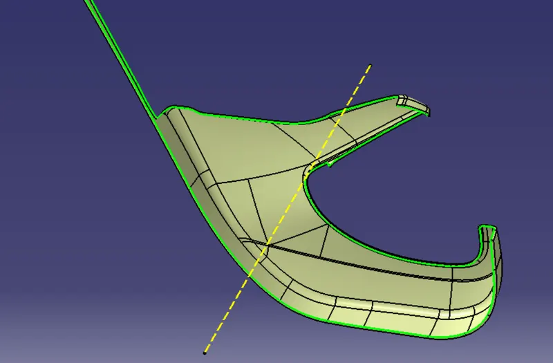
Closed and Solid body
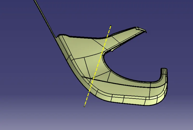
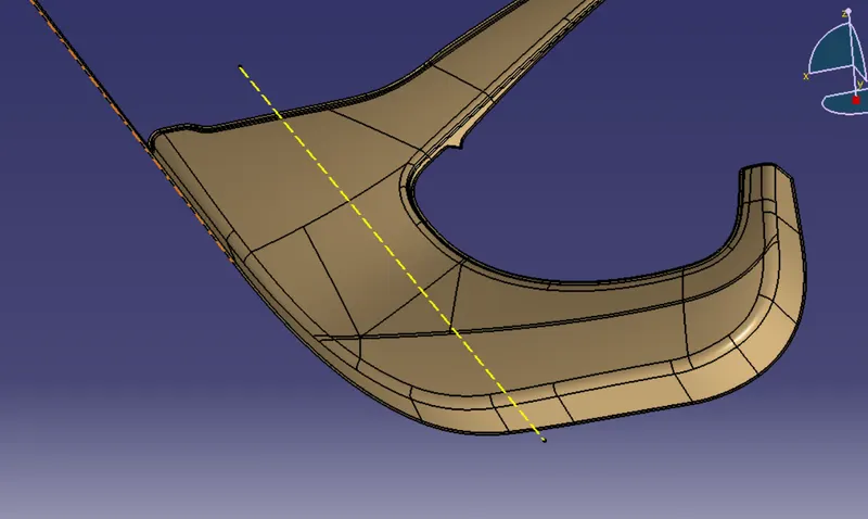
Attachement features
Heat stakes
Heat stakes are used to join two or more parts that are made of plastic with the help of the heat staking process. The heat staking process involves the deformation of the plastic material using heat and force to fix it with the other parts.
To create the Heat Stake, we need to create a sketch with a circle of diameter 8mm. Now extrude this sketch to a height such that it is passing through the Flange. Using the shell option, thicken this extrude (thickness 2mm) to form a solid and give it a draft of 0.5 deg.these heat stakes are designed as per the design rules.
Dog house
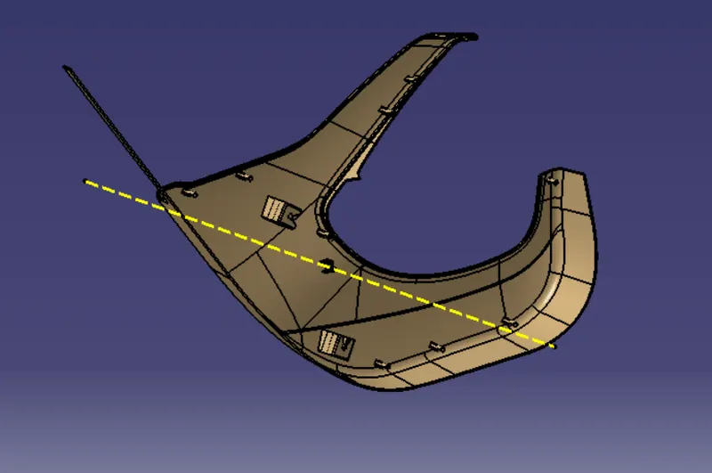
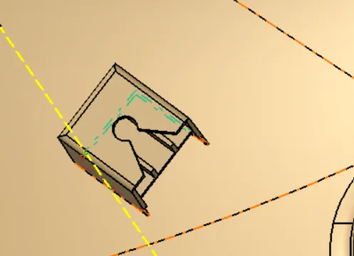
Dog house is an engineering feature used in plastic trim design. Dog houses are used as supporting feature. Sometimes other engineering features like snaps; locators etc. are mounded on them to increase their strength. Dog houses are subjected to draft analysis to prevent breakage of the component during ejection from mould cavity. Dog house and other engineering components are built on B-surface
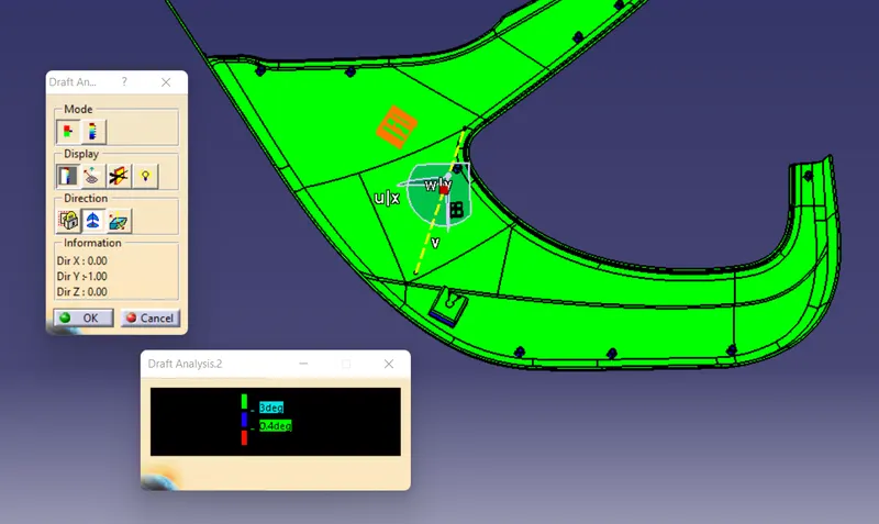
Draft analyis
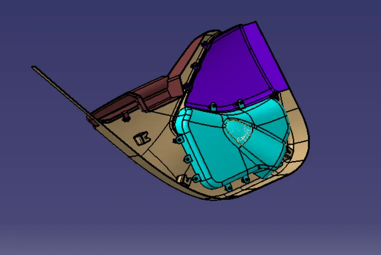
Assembly
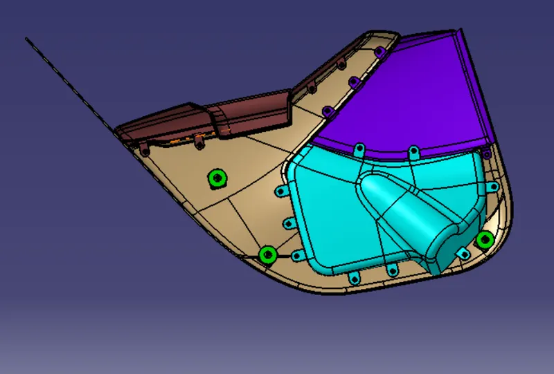
After creating the solid body and attachement features of all the parts we can assemble by fixing lower substarte and using constrtaints assembling all other parts
Push Pin clip
Push Pins are used for joining one component to another and are attached to the Dog House.
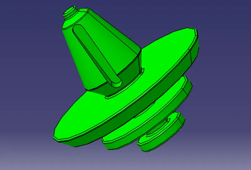
Assemble the push pins on the dog house by creating axis and using constratints
Conclusion:
CAD model of Door Trim Panel with attachment features considering the given inputs, design rules and following the OEM standards is created.