Roof challenge
Aim: To design the Car roof creating its essential flanges and reinforcements using the given roof styling design.
Introduction:
An automobile roof is considered as a part of BIW design. An automobile roof or car top sits above the passenger compartment, protecting the vehicle occupants from sun, wind, rain and other external elements. It also offers aerodynamic support to the car while in motion.
Types of Roofs:
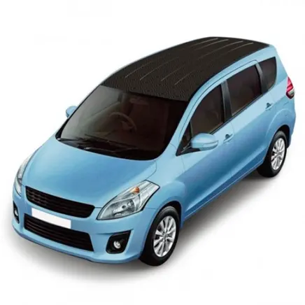
Hardtops - When we talk about hardtops, we refer to the common rigid forms of automobile roofs we see around. This type of roof is made from metal or plastic in modern-day cars.
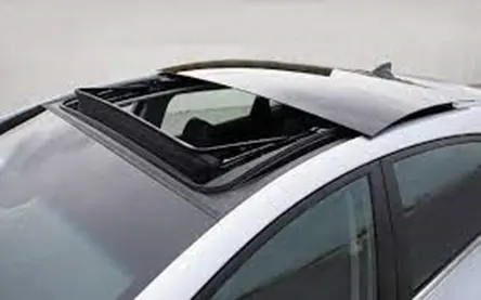
Sunroof - A sunroof is an operable type of roof that allows for an opening in the roof of an automobile; say a window in a roof. It can allow either light or air or both to enter the vehicle. They are either operated manually or automatically.
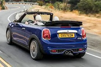
Convertibles - convertibles are passenger cars that can be driven with or without the entire roof in place. They have first introduced as open-air vehicles; no roofs, no sides.
A roof panel assembly includes a roof outer panel/ditch area and inverted hat like reinforcements rails which underlie the outer side edges of the roof outer panel. Roof rails are provided to give strength to the outer panel and also provide support to other commodities present in a car.
There are different rail reinforcements in a roof panel like
- Front roof rail
- Bow roof
- Center roof rail
- Rear roof rail
Front roof rail - Front roof rail is used to provide strength to the roof panel and it also acts as a link between windshield glass, roof panel, and headliner. Headroom clearance and visibility criteria should be considered the important factor while designing the front roof rail
Bow roof - Bow roofs are again the roofs that will provide support to the roof panel by increasing its strength. The position of the bow roofs is the very factor that needs to be considered. The bow roofs should be straight
Center roof rail - This is a roof rail that will at the center of the roof to provide strength and stability to the roof. The center roof rail will be a straight roof rail
Rear roof rail - Rear roof rail is again used to strengthen the roof and this acts as a link between the roof panel and the back glass which is connected to the backdoor of the car
Safety point of view roof plays a very important role especially in roll-over accidents vehicle rollover crashes are the cause for several head, neck and spine injuries for this reason stiffness and strength of any vehicle is crucial, in order to achieve this embosses with reinforcements are provided on the surface of the roof.
Roll over crashes are usually destructive accidents. Vehicle damage often include deformation of roof and its supporting structures. Strengthening the roof is suggested as counter measure to avoid injuries and deformation of roof. For this reason, the strength is very important criteria in designing the roof
Roof crush test
Roof Crush Resistance, establishes strength requirements for the passenger compartment roof of passenger cars, multipurpose passenger vehicles, trucks and buses with a GVWR of 2722 kilograms or less. The purpose of the standard is to reduce deaths and injuries due to the crushing of the roof into the passenger compartment in rollover accidents. The standard does not apply to school buses and passenger cars that conform to the dynamic rollover test requirements of FMVSS 208, Occupant Crash Protection, and S5.3 by means that require no action by passenger car occupants. It also does not apply to convertibles, except for optional compliance with the standard as an alternative to the rollover test requirements in S5.3 of FMVSS
The prescribed static loading device is a rigid unyielding rectangular block 762 millimeters by 1,829 millimeters. It shall not move more than 127 millimeters to achieve the specified resistive load when applied to the forward edge of a vehicle’s roof – see Figures 1 and 2. The resistive load to be achieved is 1½ times the unloaded vehicle weight (UVW) of the test vehicle or 22,240 Newtons, whichever is less
The force shall be applied in a downward direction perpendicular to the lower surface of the static loading device at a rate of not more than 13 millimeters per second until reaching the compliant resistive load. The test shall be completed within 120 seconds. The static loading device shall be guided throughout the test so that it moves, without rotation, in a straight line with its lower surface oriented as follows and as shown in Figure
The design considerations for the roof are
- Visibility criteria
- Head clearance
- Heat distortion and snow load criteria
- Draft analysis
- Safety parameters
We have the following data from the styling team to design the roof and its parts
- Surface of the roof
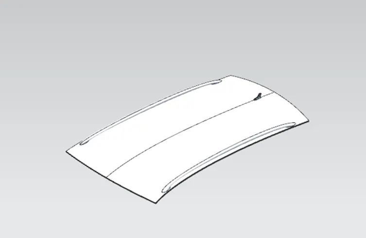
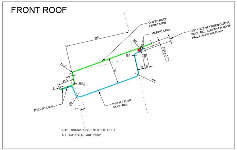
- Master section of front rail
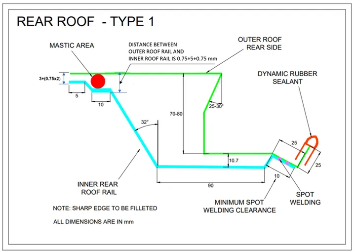
- Master section of rear roof rail
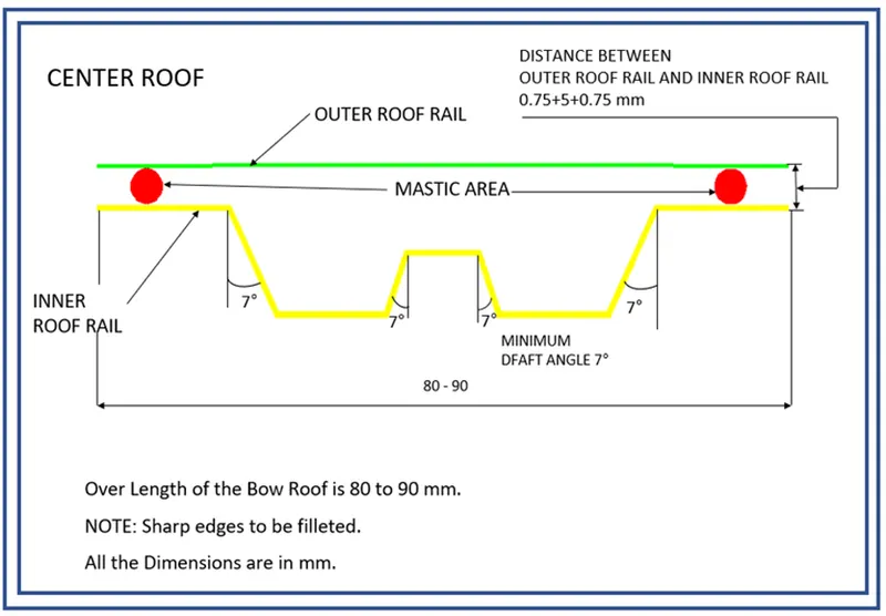
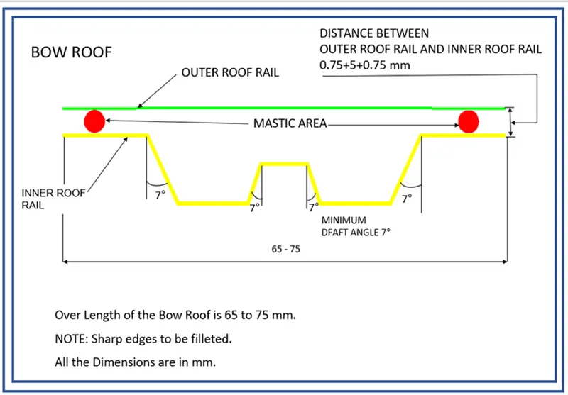
- Master section of center bow and bow roof rail
Design procedure
Front and rear ditch area
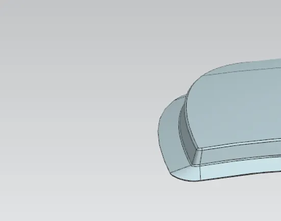
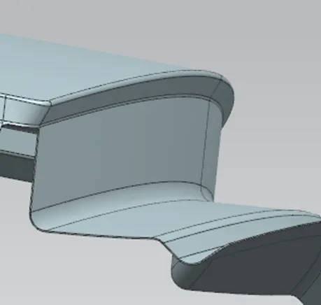
Extract the surface from the data given by styling team and master section, create front ditch area by extending the sheet around 15 mm with positive draft angle 3 deg. For the rear ditch area, we have to design by considering the rear door rotation axis. We have to give negative draft as shown in the master section on purpose to make sure that the leading edge of back door can travel through a trajectory while opening and closing
Front roof rail
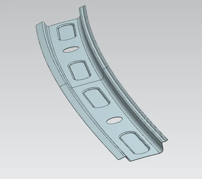
Front roof rail is used for supporting the roof for externally applied forces occurring at accidents. When we increasing the front roof rail is good for strength but also it is not for drivers because of it hide visibility of road. When considering the parameters of roof rail, give them 60-80mm length, proper draft angle and also using the embosses for increasing the strength. Front section of front roof rails spot welded to the front ditch area and other end is fixed with help of mastic sealants.
Rear roof rail
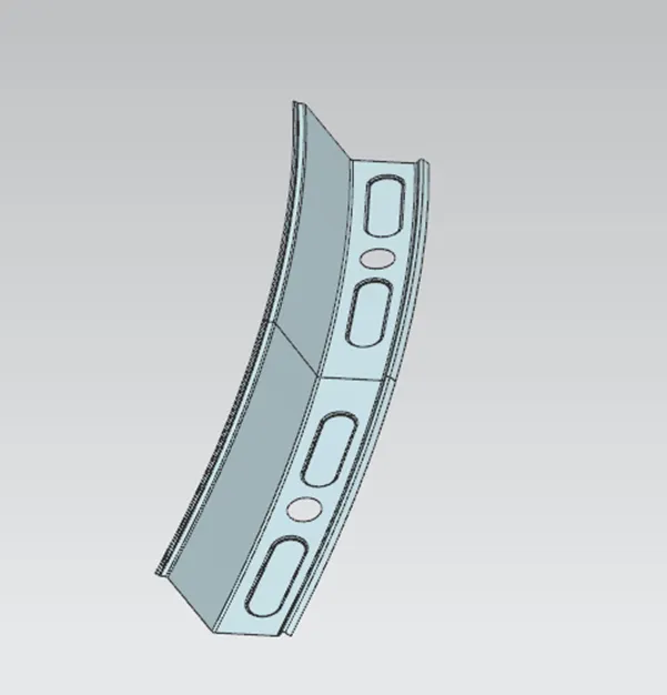
Rear roof rail is creating to length 80-100mm with proper draft angle. Give embosses on the sheet to ensure the enough strength for holding the roof structure. When considering the all parameters like length, width, sealants, rubber materials, wind shield to create the design properly. Sharp edges are avoided gave a smooth curvature.
Front and Rear bow roof
The bow roof is given to improve the load bearing capacity of the roof structure. Longer the roof area we have to give the greater number of bow roof to the structure. Positioning of the bow roof is decided by the curvature study. The heat distortion and snow load conditions are checked to analyze the given position of bow roof. Mastic area are provided to bow roof to give more strength and to fix on the roof structure.
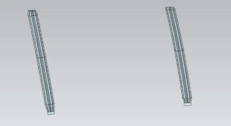
Center roof rail
Center roof rail is effective support to the flat area structure roof. Because of center area of roof is more susceptible to failure under action of load. Usually, Reinforcement center roof rails are fixed at the center of the roof for connecting to the B – Pillar support structure, it will used for roll-over test.
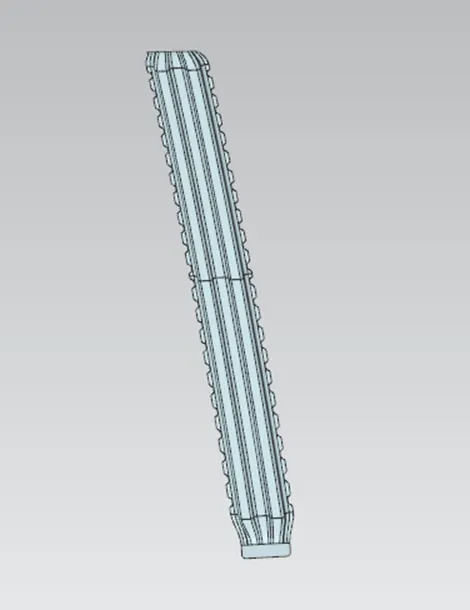
Curvature study
After designing all the components, we have to do the curvature study to check the weather the roof having enough strength as per the positions of reinforcements and can with stand from deformations at different conditions
The curvature of roof study is based on two conditions
- Heat distortion criteria and its calculations
During in summer days or in some high temperature regions or countries, the roof of the car is exposed to the more heat. At that time, the roof can be capable of deformation. So for that while designing the roof, heat distortion study is the important parameter to be considered. This study helps us to check the roof can withstand from deformation or not as per the position of bow roof.
We have the bow roof prediction formula.
W = [1.73 x 10^(-3) x L] + [1.85 x 10^(-8) x (R^2)/t] + [ 1.10x10^(-3) x l] - 2.68
Where,
L = Roof Length in X-Direction[mm](Roof dimension in 0-Y)
R = Roof curvature
R = 2(Rx*Ry)/(Rx+Ry)
Rx = X curvature
Ry = Y curvature
t = Roof plate thickness [mm]
l = Bow Roof Span [mm]
Judgement condition: Ok< 2.7
Steps for calculation
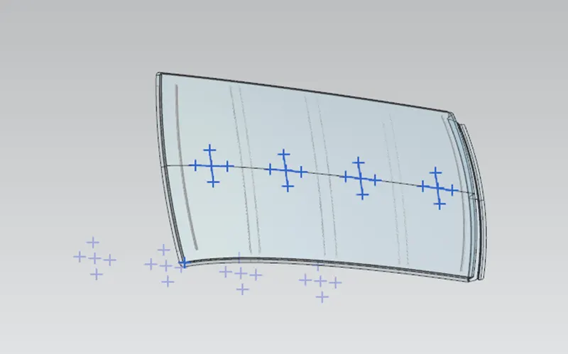
- Draw the 0-Y axis line for indicating exact Center intersection of the roof
- Draw a line in downwards at a distance of 300mm from 0-Y axis line(-3Y)
- Offset the -3Y line at a distance of 100mm on both sides
- Now the vertical center lines are drawn between each adjacent roof rail edges and from that center lines, offset the lines to distance 100mm on both sides
- Generate the intersection points where the vertical lines and horizontal lines are intersected
- Make all the sketch geometry into construction geometry except the intersection points and exit from sketch
- Project the intersection points onto the surface of roof using 3D project curve feature
- Using three-point arc, join the intersection points and measure the minimum radius (Ry& Rx values)
- Measure the overall length of the roof(L) except ditch area and measure Bow roofs span(l)
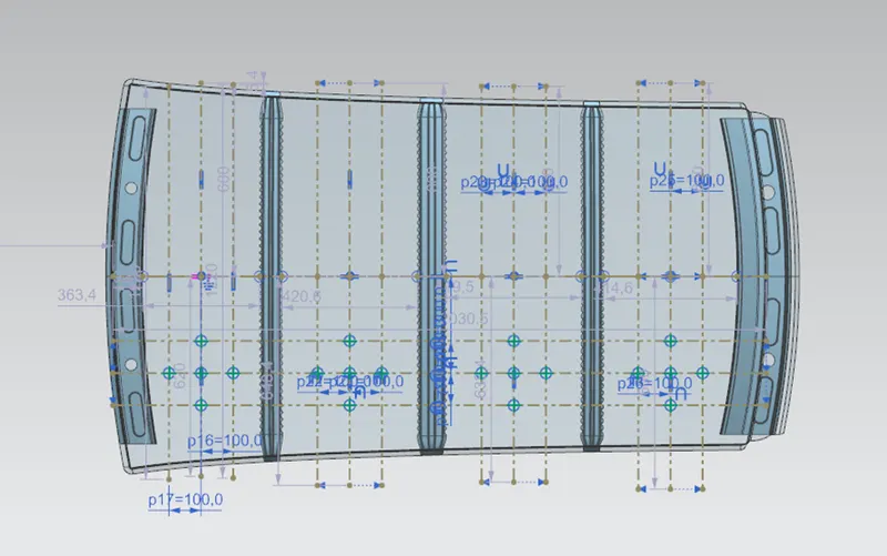
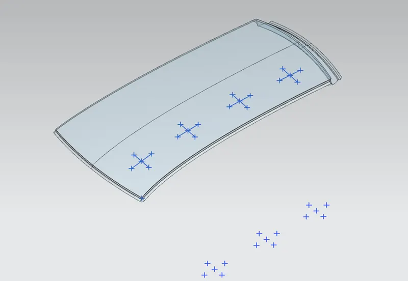
The final result can be shown in the below table
| Heat distortion calculation | |||||||||||
|
Sl .no |
Row |
L(mm) |
Rx (mm) |
Ry (mm) |
Rx*Ry |
Rx+Ry |
R |
t (mm) |
l(mm) |
W |
Result |
|
1 |
FR- Bow1 |
2030.5 |
5741.069 |
2456.933 |
14105421.9 |
8198.002 |
3441.185 |
0.75 |
363.4 |
1.524602 |
OK |
|
2 |
Bow 1- CR |
2030.5 |
5014.613 |
6026.695 |
30221543.1 |
11041.31 |
5474.269 |
0.75 |
420.6 |
2.034626 |
OK |
|
3 |
CR- Bow 2 |
2030.5 |
4020.268 |
10364.25 |
41667054.6 |
14384.52 |
5793.32 |
0.75 |
419.5 |
2.122091 |
OK |
|
4 |
Bow 2-RR |
2030.5 |
3283.529 |
14591.24 |
47910749.8 |
17874.77 |
5360.714 |
0.75 |
414.6 |
1.997677 |
OK |
For the above table, we can conclude that the valve W satisfying the given condition which is less than 2.7, so the roof can with stand the deformation as per given respective position of bow roof under heat distortion.
Snow load criteria
In some regions and snow-covered countries, the snowfall will be more. At that situation the snow will accumulate on top of roof and the load on the top of roof will increase. The roof should with stand the load and the deformation should be elastic. so while designing the roof of considering the snow parameters, snow load criteria study helps us of determining the strength of roof as per the position of bow roofs.
For that we cave prediction formula
Qr = [Iy x t2] / [α x s x [(Rx + Ry)/2]2 x 10-8]
Where,
α = My x Lx2 x 10-12 , My = Y(Ly-Y)
t = Roof plate thickness [mm]
Ly = Distance between the front and rear roof Rails on the Vehicle along with 0Y[mm]
Length of Roof panel with the centre point between Roof rail Front /Rear as the front and rear reference point.
Lx = Distance between the Left and Right end of the roof on the Roof BOW [mm]
The width of the roof panel is exposed on the surface.
Y = Distance front Front Roof Rail to Roof BOW[mm]
s = Distance for which Roof BOW bears divided load [mm]
s = L1/2 + L2/2
Iy = Geometrical moment of inertia of Roof BOW (Y cross-section )[mm4]
Rx = Lateral direction curvature radius of roof panel Y cross-section on Roof BOW [mm]
Roof panel curvature Radius of the Length Lx in Front view
Ry = Longitudinal Direction curvature radius of the Roof panel X cross-section on Roof BOW [mm]
Roof panel X curvature radius of length s in Side view
Judgement condition Qr>3.1
Steps followed
- Draw the 0-Y axis line for indicating exact center intersection of the roof
- Offset the 0-Y line at a distance of 100mm on both sides
- Now the vertical Centre lines are drawn between each adjacent roof rail rail edges and from that center lines, offset the lines to distance 100mm on both sides
- Generate the intersection points where the vertical lines and horizontal lines are intersected
- Measure the Lx and Ly values
- measure the Y, L1 and L2 values
- Make all the sketch geometry into construction geometry except the intersection points and exit from sketch
- Project the intersection points onto the surface of roof using 3D project curve feature
- Using three point arc, join the intersection points and measure the minimum radius(Ry& Rx values.
To get the valve of moment of inertia we have to do section inertia analysis
Section inertia for front roof rail
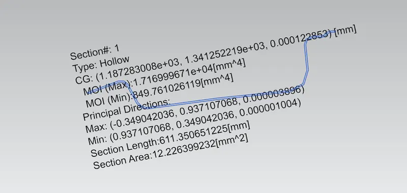
Section inertia for front bow roof rail
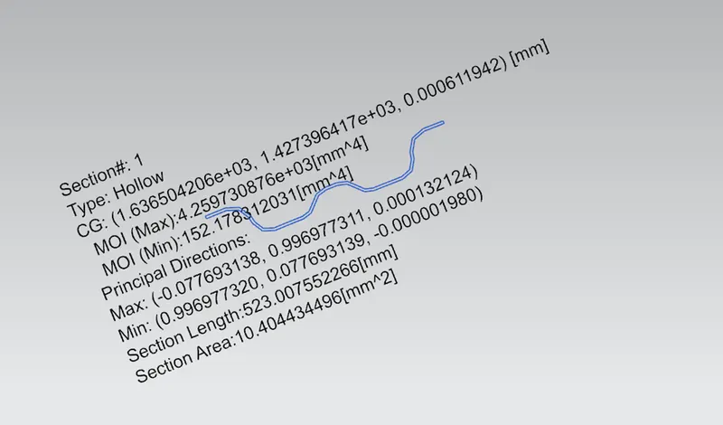
Section inertia for center bow roof rail
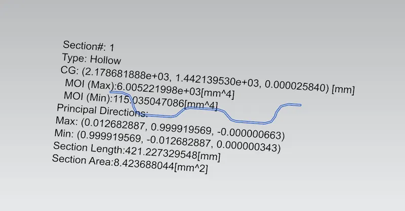
Section inertia for rear bow roof rail
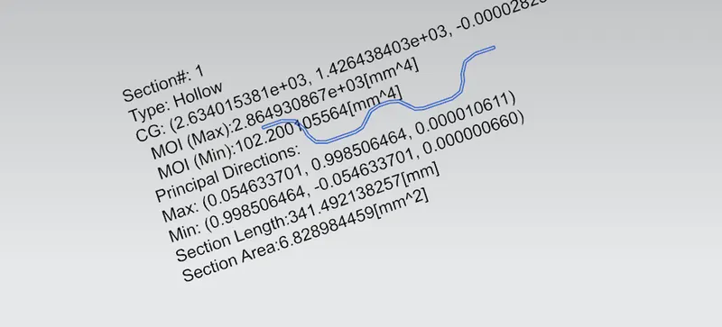
So, all the required valves are obtained and can calculate the snow load criteria
The measured vales and final result can be represented in the below table
|
Snow Load Criteria |
||||||||||||||||
|
Sl .no |
Row |
Iy (mm4) |
L1(mm) |
L2(mm) |
Ly(mm) |
Lx) |
Rx |
Ry |
t |
Y |
S |
My |
R |
α |
Qr |
Result |
|
1 |
FR- Bow1 |
152.178 |
448.8 |
500.2 |
2030.5 |
1110.8 |
4623.38 |
2472.735 |
0.75 |
448.8 |
474.5 |
709867 |
3548.058 |
0.875888 |
16.36094 |
OK |
|
2 |
Bow 1- CR |
115.035 |
500.2 |
500.2 |
2030.5 |
1071.6 |
3760.83 |
5971.417 |
0.75 |
500.2 |
500.2 |
765456.1 |
4866.124 |
0.878994 |
6.215226 |
OK |
|
3 |
CR- Bow 2 |
102.2 |
500.2 |
560 |
2030.5 |
1050.6 |
4250.531 |
10762.73 |
0.75 |
500.2 |
530.1 |
765456.1 |
7506.632 |
0.84488 |
2.277877 |
NG |
As we can see from the table the 3rd case in not satisfying the given condition
The roof cannot with stand from snow load.
In order to increase the strength, we have different possibilities
- We can rechange the size and position of the bow roof rail
- Changing the curvature of the roof
- Creating the emboss on the roof can increase the strength
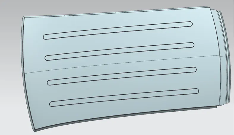
Based on these possibilities I have created the emboss on the roof surface to increase strength. As changing the bow roof structure and position will consume a lot of time, and changing the curvature of roof will change the looks of the entire car. So the best possibility is to create the emboss on roof surface.
Draft analysis
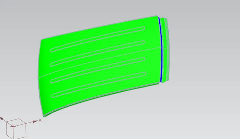
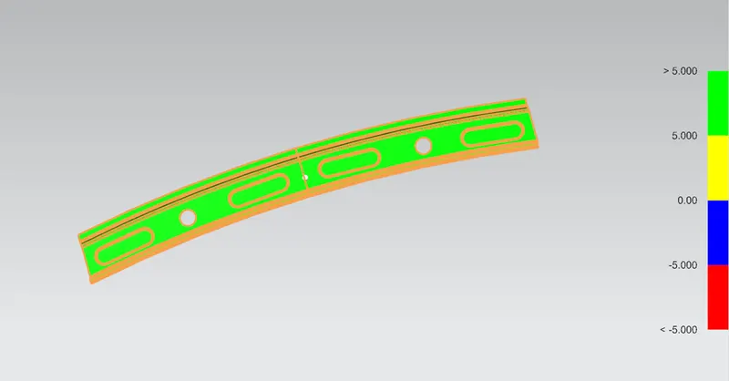
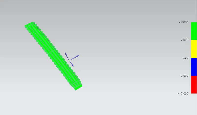
Draft analysis is a tool to check the correct application of draft to the faces of their part and verifies the draft angles or examine angle changes within a face. It commonly detect whether the designed component within the positive draft or negative draft. Positive draft means the angle of face with respect to the direction of pull is more than reference angle. Negative draft means the angle of face with respect to the direction of pull is less than the reference angle
Draft analysis for roof structure
The blue and red zones are appeared as we have given negative draft on purpose to make sure that the leading edge of back door can travel through a trajectory while opening and closing.
Draft analysis for front roof rail
Draft analysis for rear roof rail
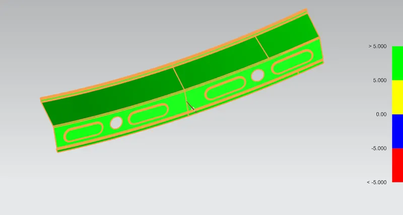
Draft analysis for Bow roof 1 and 2
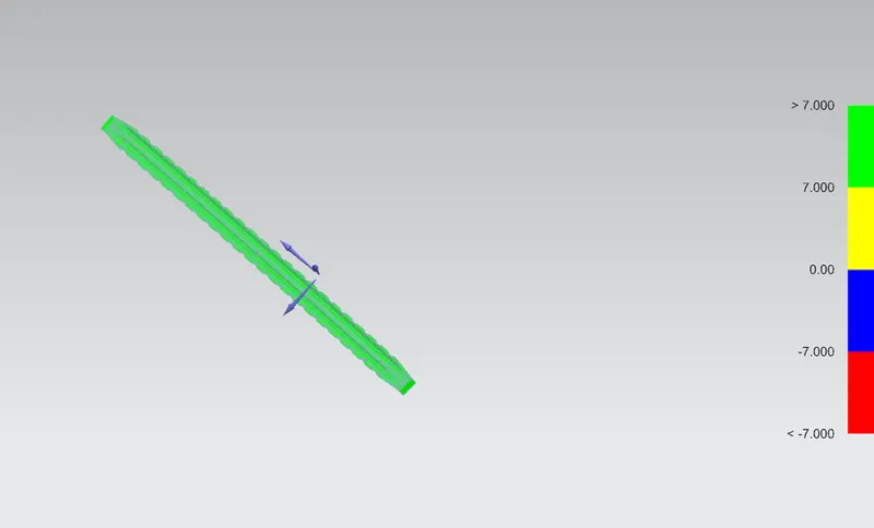
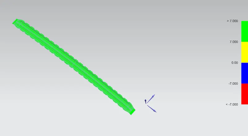
Draft analysis for Center bow roof
Conclusion
- Roof along with its respective strengthening reinforcements components can be successfully designed and assembled by following given master data.
- Done the hear distortion and snow load criteria calculations and based on the results gave extra strength to the roof structure
- Draft analysis is carried out to check the components are in positive draft or negative draft.