Week 9 - Attachment Feature Creation (Ribs & Screw Boss) - Challenge 1
Objective:Creating the rib and screw boss for the Door Handle considering the design rules.
Class A surface of the Door handle is given for designing the plastic component
Class A surface
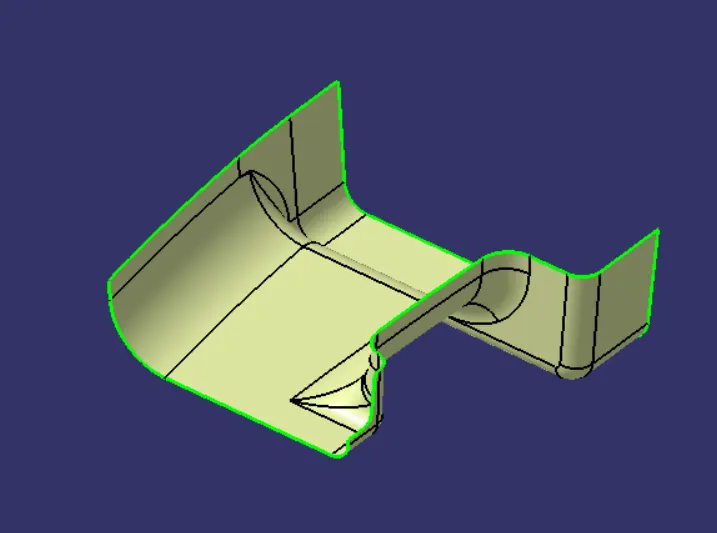
Tooling direction
From the class A surface the walls of the handle are perpendicular so we can take the tooling drection as normal to the base surface.
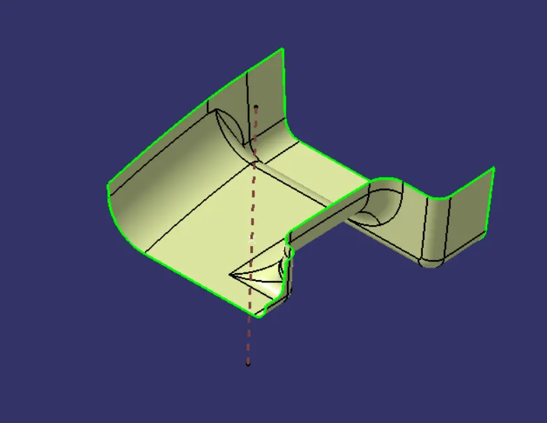
After defining the main tooling axis draft analysis for a postive draft of 3 deg
Draft analysis
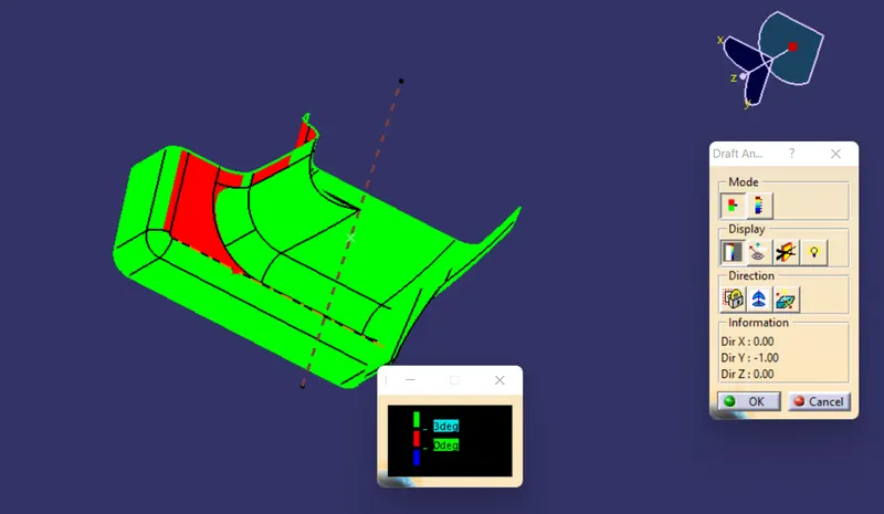
From the draft analysis we can check for the negative draft. the red area on the class A surface have the negative draft. Which makes it difficult to manufature
Class B surface
Offset the class A surface by thickess which is 2.5 mm and correct the patches formed on the surface. Extropolate the class B surface
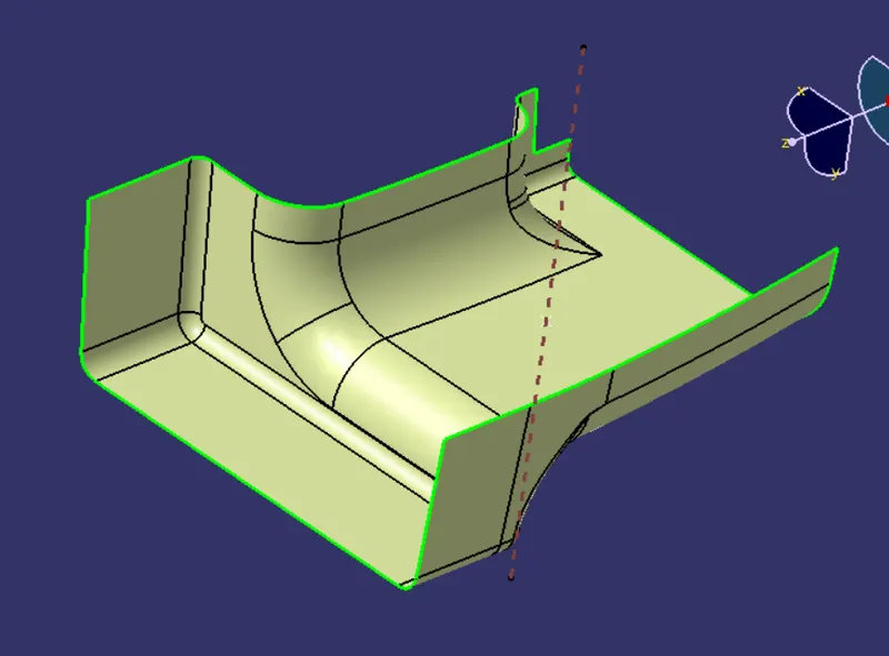
Class C surface
Extract the boundary of class A and sweep with referance to the surface at 90 deg with a length more than the thickness of the component. Join class A and sweep
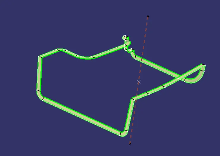
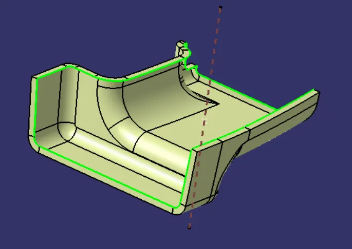
Trim the Class C with class B to get closed surface and used closed surface to get solid body
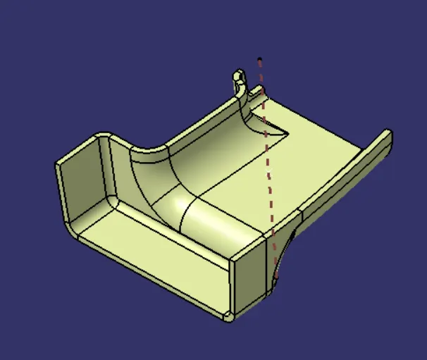
Rib design
The rib is designed with the below design considerations
Thickness - 0.4* t = 0.4 * 2.5 = 1mm
Height - H ≤ 5t = 2.5 * 5 = 12 mm
Draft angle - ≥ 0.5 deg
Fillet radius - 0.25 mm max
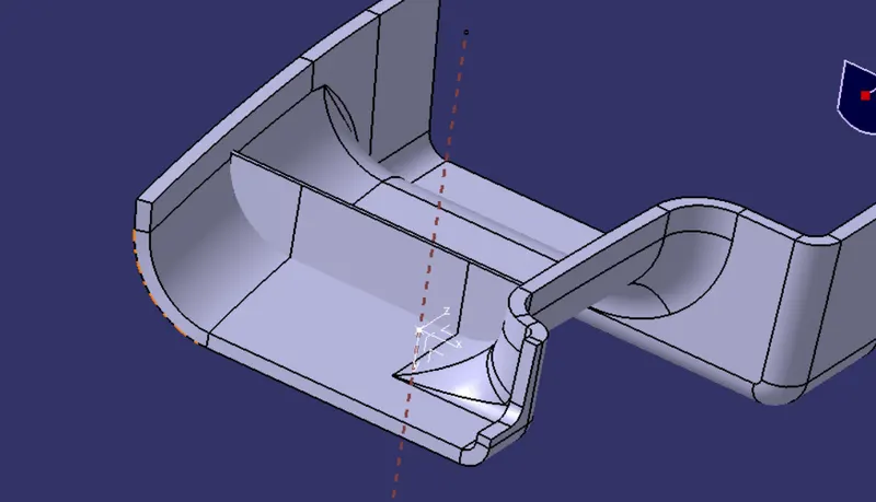
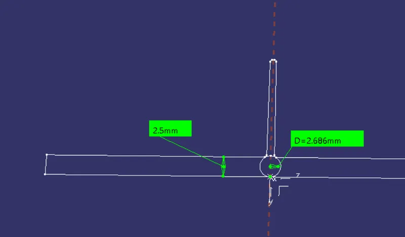
Similar way another rib is also can be created
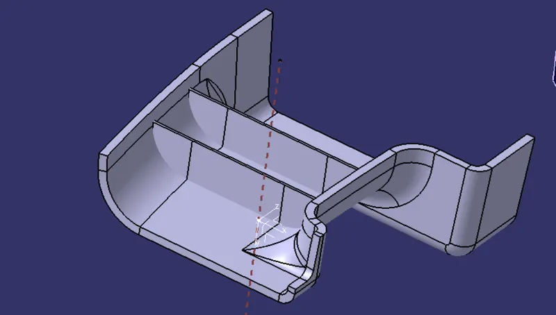
Screw boss
The screw boss is designed with the below design considerations
Ideal wall thickness of screw boss- 0.6 * T
FIllet radius - 0.25 mm max
Draft - 0.5 deg
Height to dia ratio - 3:1
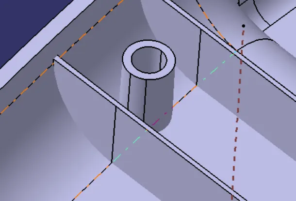
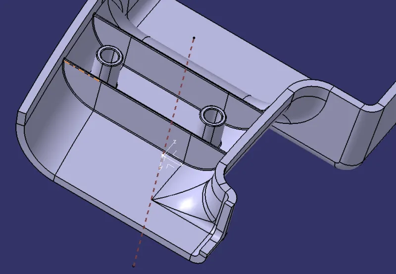
screw bosses are created with the given dimension and sketch
Tree structre of geometrical set and body
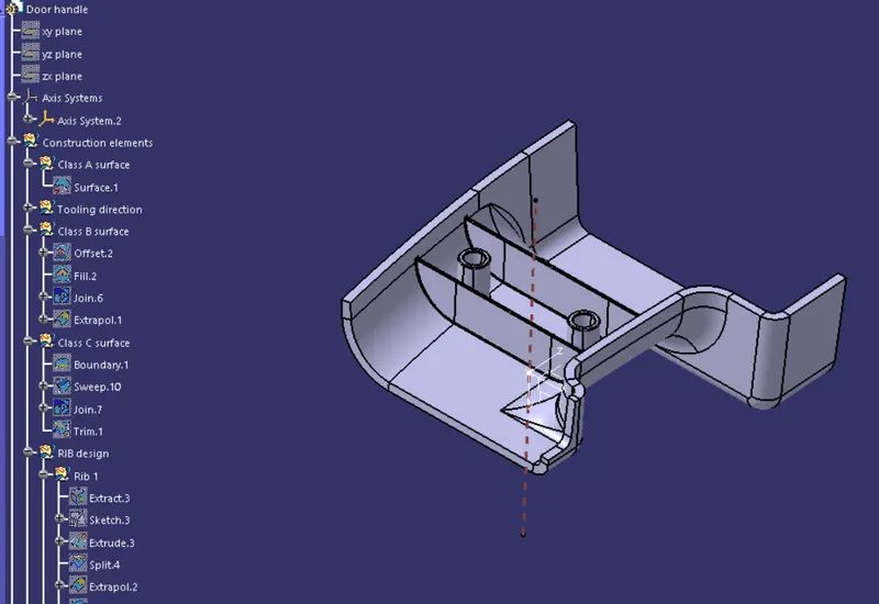
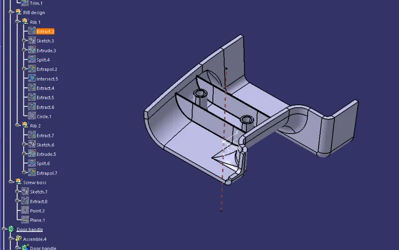
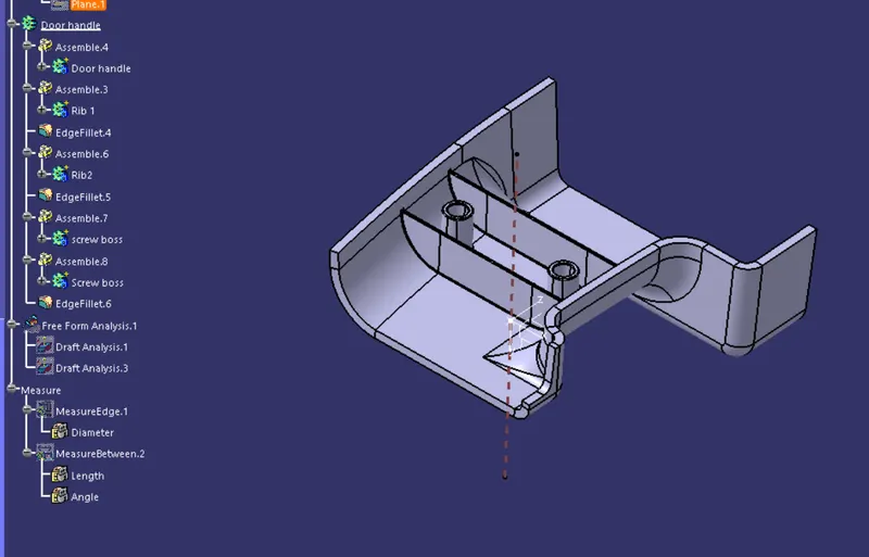
Draft analysis for Rib and screw bosses
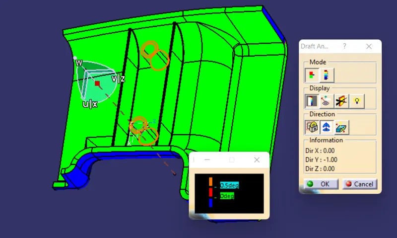
By using draft angle of 0.5 deg the draft analysis is done and from the image we can say that the ribs and screw bosses have positve draft
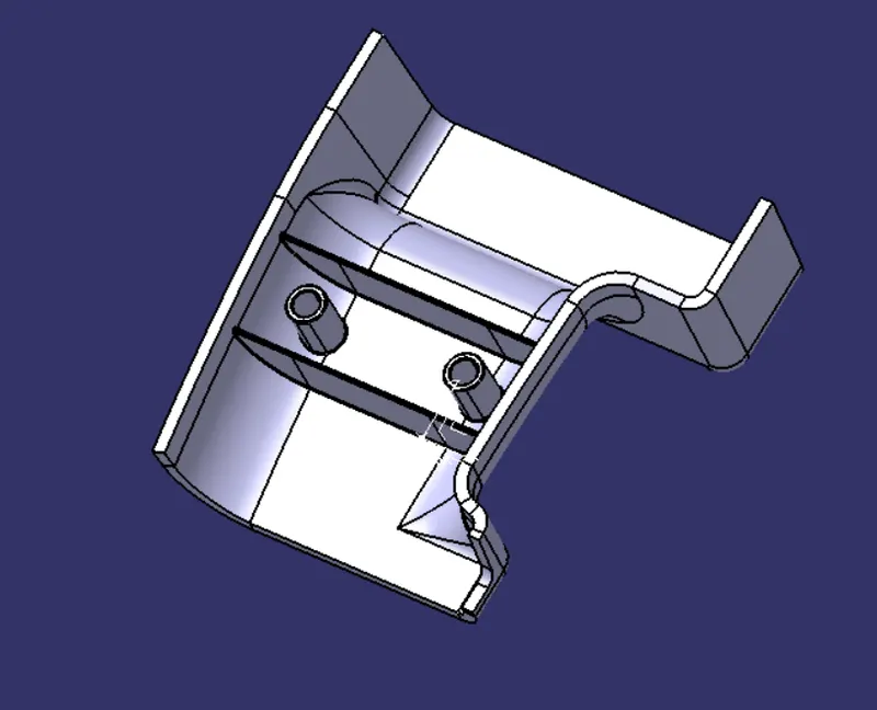
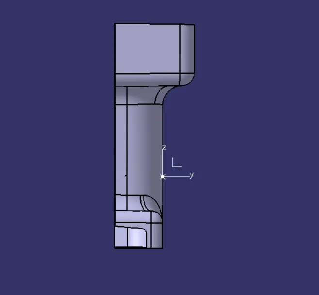
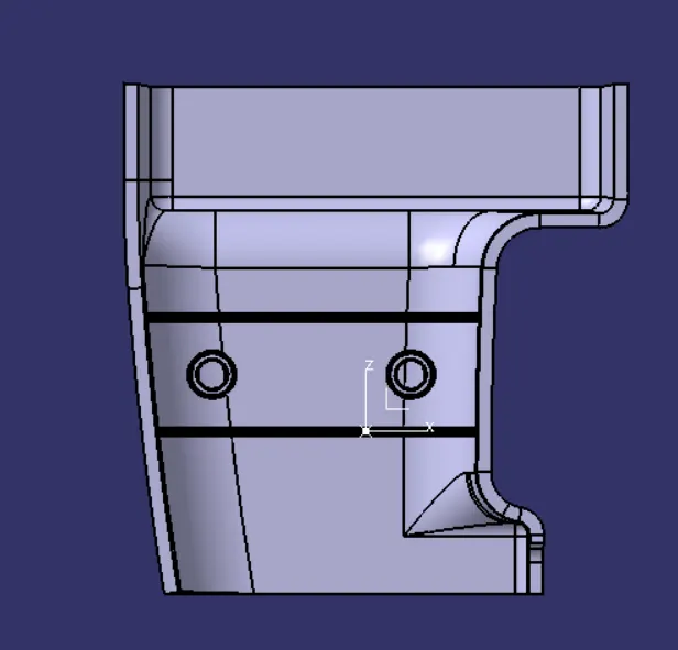
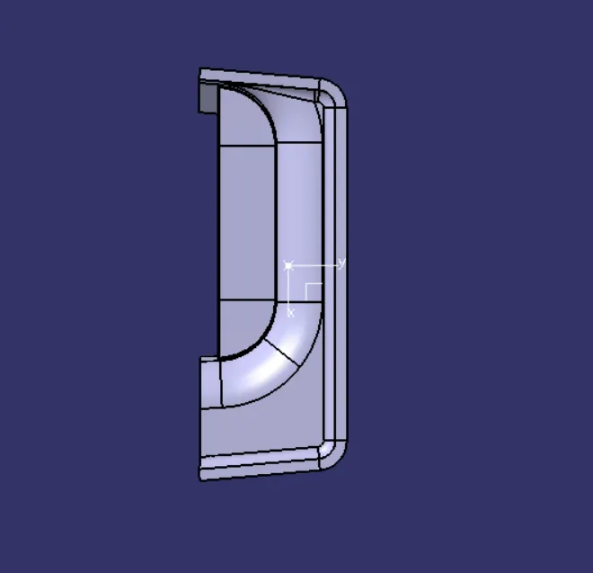
Part body in various orientations (Isometric, Front, Side, and Top View)
Isometric view
Front view
Side view
Top view
Conclusion: Rib and screw boss is created for the Door Handle considering the design rules.