Week 8 - Challenge 6 - Core & Cavity Design
Objective: Creating the Core and cavity blocks for the switch bezel designed in the earlier challenge.
Class A surface of the switch bezel is given for designing the plastic component
Class A surface
It describes the final production surface data for the aesthetic parts
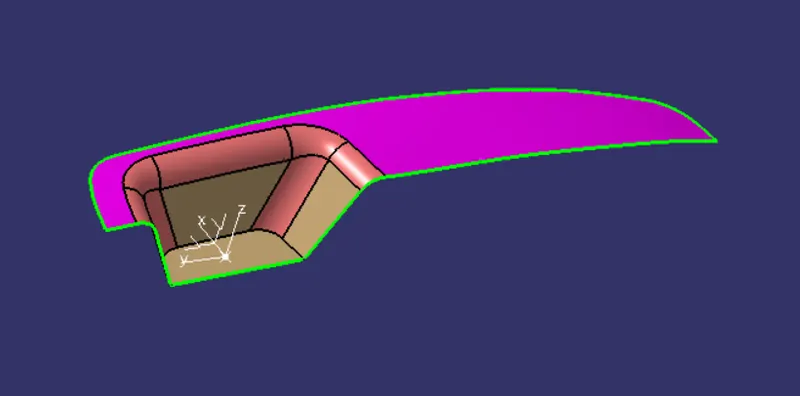
From the given Class A surface a dummy tooling direction is created on the feasible surface. Here i have created the dummy tooling direction on the slope surface and created an intrestion on the surface at tooling axis by creating a sketch. From the sketch obtained at intersection we can check the wall angles which are most parallel to tooling axis and created lines and defined bisecting line for main tooling axis.
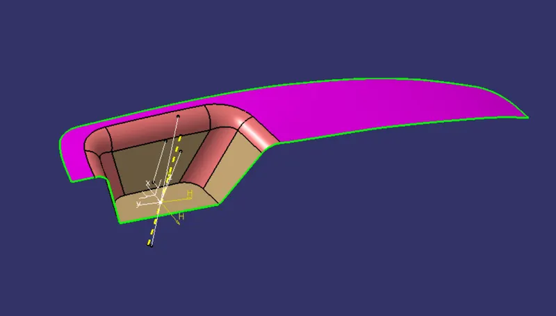
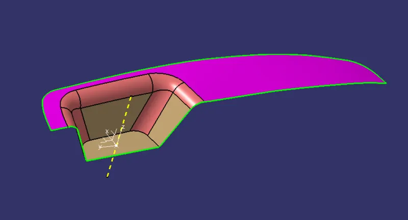
After defining the main tooling axis draft analysis for a postive draft of 3 deg
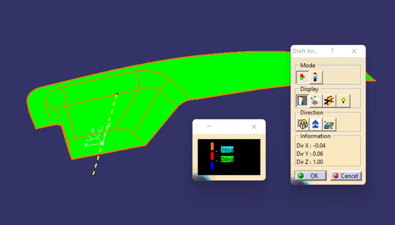
Draft analysis is done for the final closed body
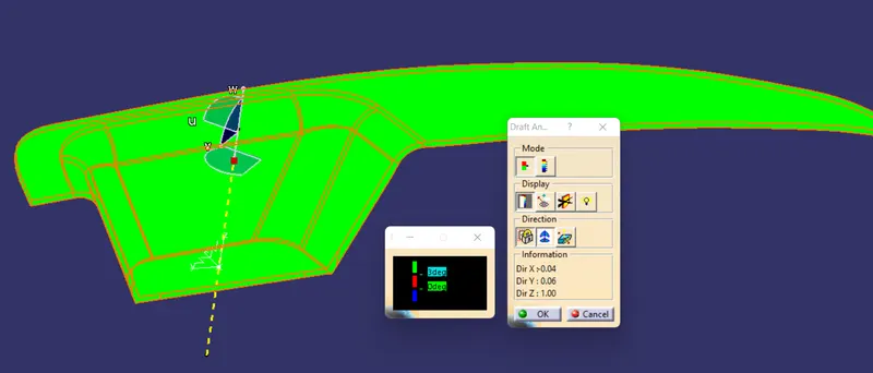
The green colour on the surface represnets that there is no negative draft
Core and Cavity design
We have to create the parting surface before creating the core and cavity, by checking the draft we can decide which side to be given as parting surface
Parting surface is where the two meet when the mold is closed, or the surface that splits the workpieces or mold components in the mold. it will cause a witness line on the surface of plastic injection molded parts,we call it parting line
I have created the parting surface by trimming the class c surface with class B towards outside creating a open surface
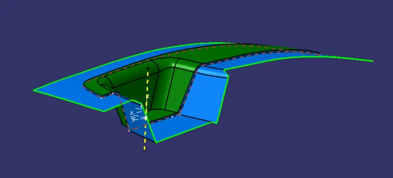
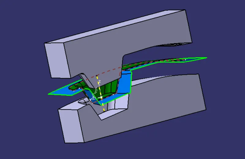
For core and cavity blocks sketch a rectangle and extrude and trim the blocks with the parting surface which gives core and cavity blocks
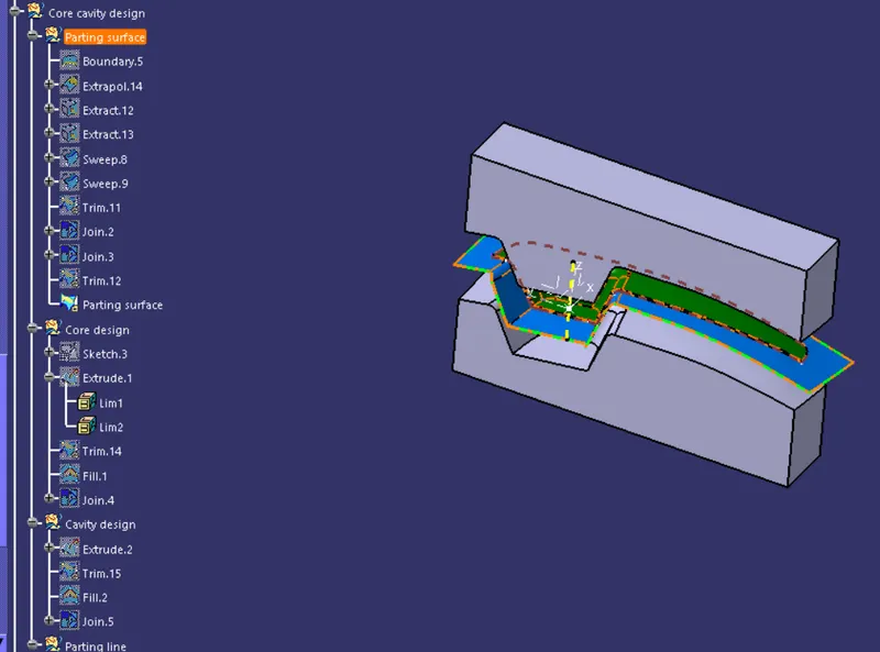
Tree structure of Geometrical set and Part body
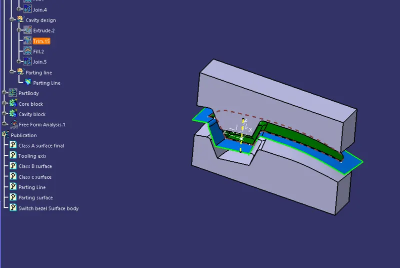
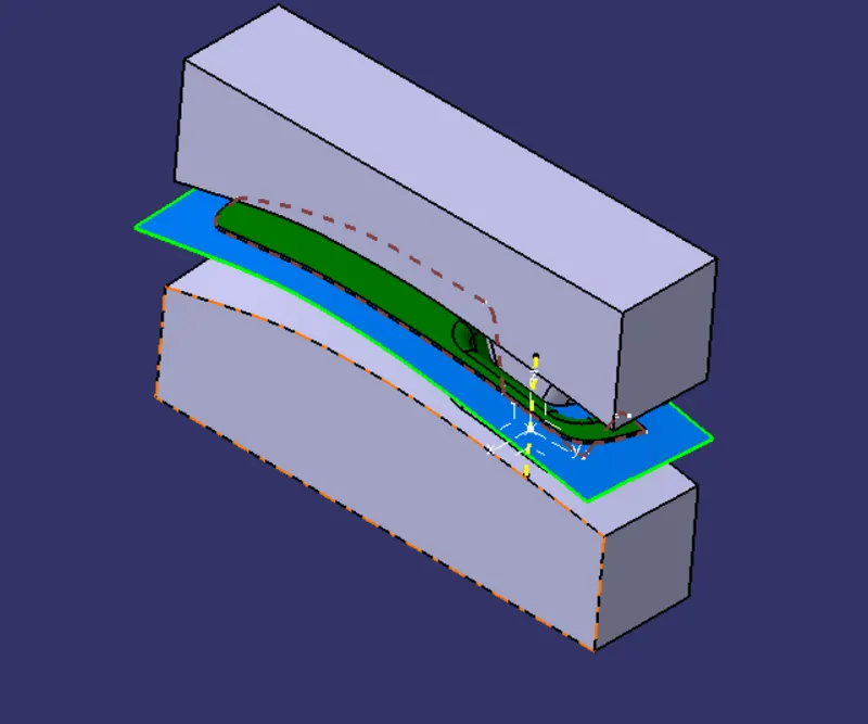
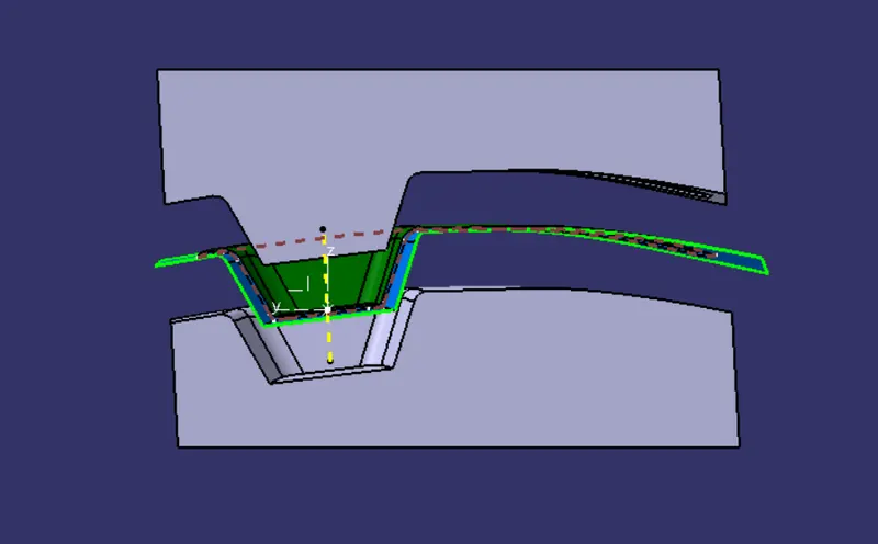
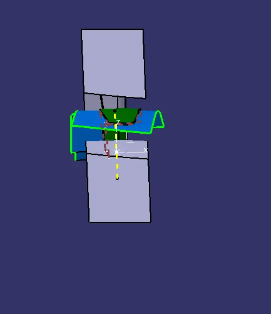
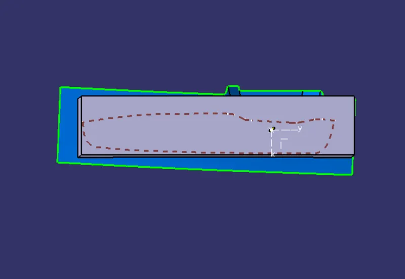
solid model with the proper color code of the draft angle in various orientations (Isometric, Front, Side, and Top View)
Isometric View
Front view
Side view
Top view
Conclusion : Core and cavity blocks for the switch bezel is designed