Project 1
Aim : TO route the wiring haress on given Engine and prepare Flatten view drawing by applying all packaging rules and protection covering as required
Introduction:
The automotive wiring harness consists of an electrical harness and the mechanical harness in the design. The current project is focused on the mechanical wiring harness and its rules and procedure to be followed while routing in the virtual condition. CATIA V5 electrical workbench is used as the CAD tool for routing the wires in the engine.
Some of the terms we should understand before designing the wiring harness.
Electrical Distribution System (EDS):
It deals with physical (location of electronic components placed in the vehicle, front end to back end) and logical (different Electrical Control Units) architecture, schematic development, power distribution (set with fuses to check wiring harness is safe in various failure modes), wiring harness design and wiring harness component design of given electrical system.
E & E Architecture:
It is a high-level logical connectivity diagram representing the number of systems, sub-systems, and logical connections between them. It is also extended to show the CAN (control area network) network between different electronic controllers.
Logical schematics:
It is detailed design of E&E architecture which is extended to show the logical connectivity between different components and controls of different systems and sub-systems.
Electrical schematics:
It is detailed design of logical schematics, which describe the pin-to-pin connectivity, properties, fusion distribution, grounding distribution, wire properties (wire type, colour, gauge), interconnects, circuit properties (circuit numbers, connector designation numbers, control device number), specification of component (rating od diode, resistors) etc., This is the end design of electrical core design of system and used as primary input for harness development.
Wiring harness topology:
It is strategy to divide the harness between different pieces to achieve the best manufacturability, serviceability and cost-effective design.
Ex: engine harness, door harness, tail gate harness.
Note: Wiring harness cannot be repaired. It is advised to replace the damaged wiring harness parts.
Wiring harness routing: It is the desired path of wiring harness into given vehicle environment by applying set of design rules and industry best practices.
Wiring harness packaging: deals with the fixing/mounting strategy of wiring harness routing to ensure the safe, reliable and durability of wiring harness by applying set of design rules and industry best practices.
Virtual environment: 3D representation of vehicle components.
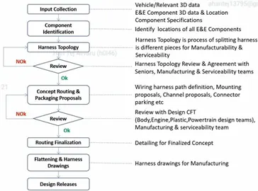
- Wiring Harness Design Process
Connector defination
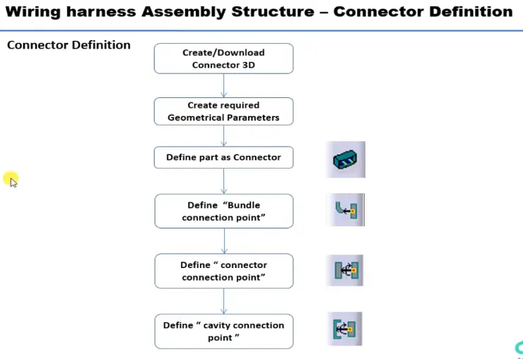
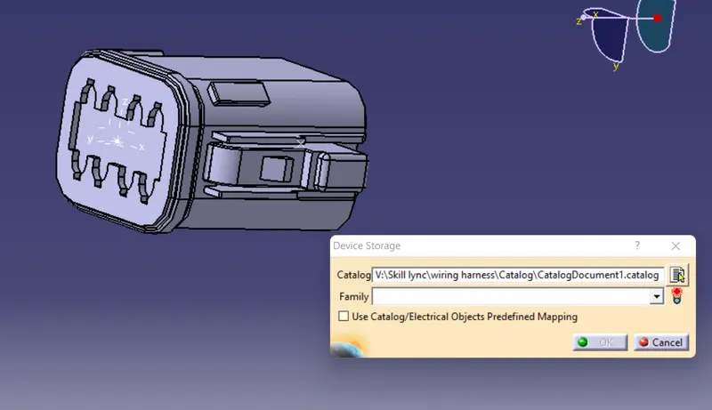
to define the connector as electrical component we have to follow the following steps
1.Download the connector from the given link or from te.com website.
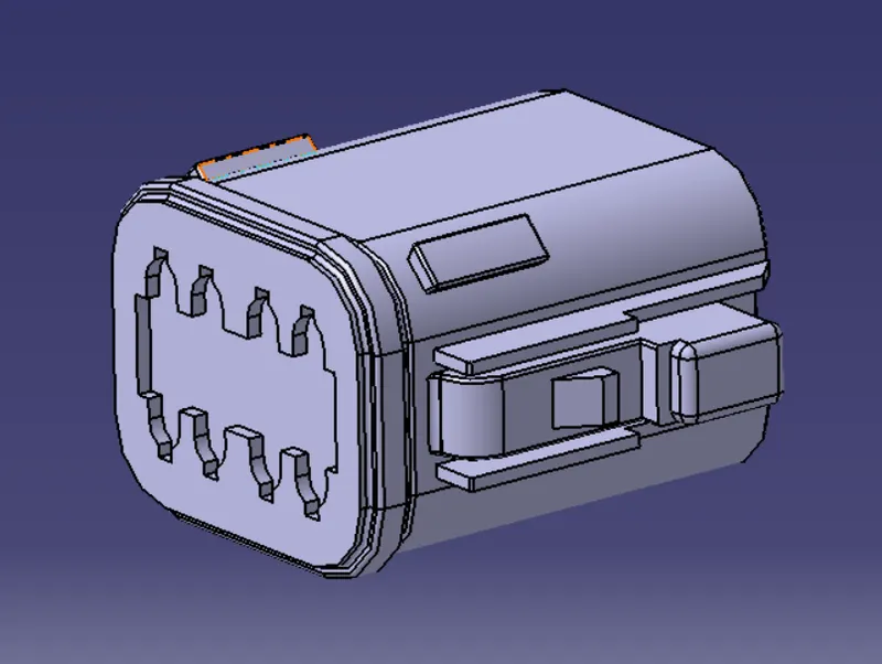
2.The connector is first opened in the part workbench and define bundle connection pint at the centre and connector connection point with axis system
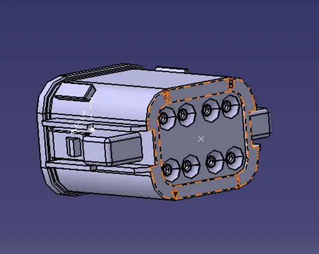
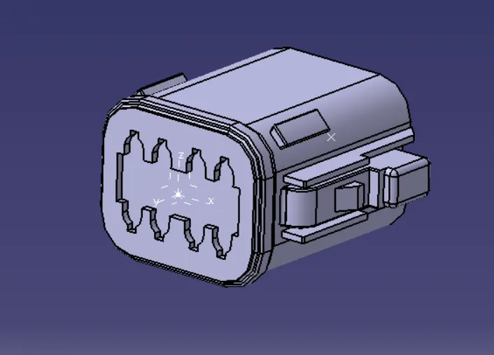
3. Now we define the part as a connector in the electrical part workbench by given the number of terminals
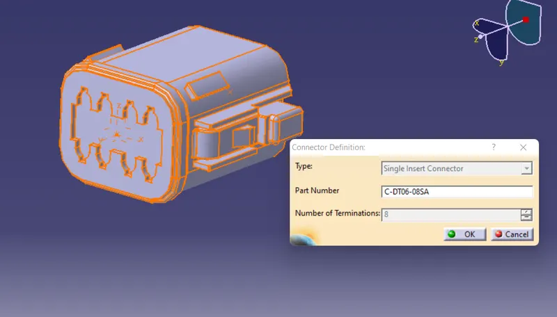
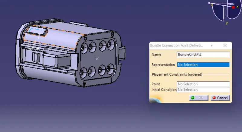
4. we have to define bundle connection point giving reperensation as the face and point as the bundle connection point and inital contact as the face of the bundle side
5. we have to define connector connecting point
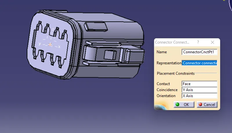
By following these steps we define the given connector as electrical connector
by using store device we can save the connector in the catalogue
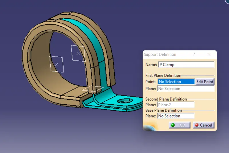
Support defination
Steps to define the component as electrial support
1. Open the component in the part design
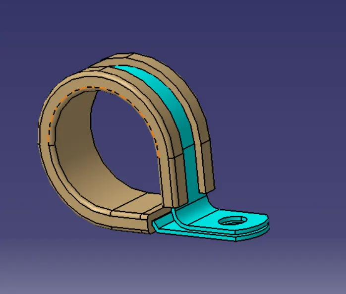
2. Create entry point and exit point
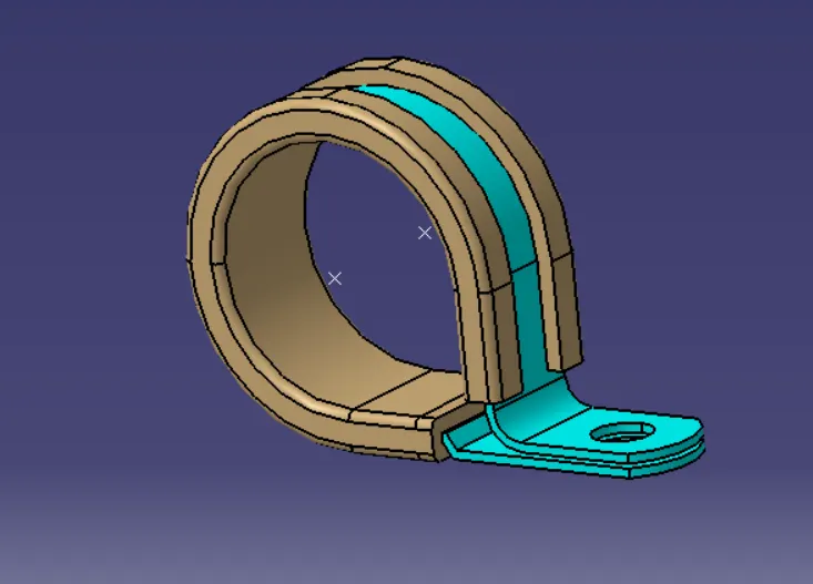
3. create entry, exit and base planes
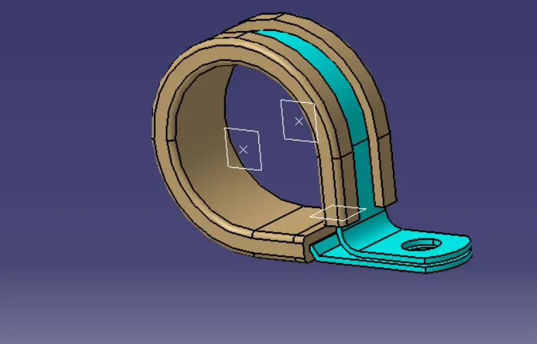
4. Open the electrical part workbench and define the support on both sides using entry plane and exit plane and base plane.
Defining protection covering
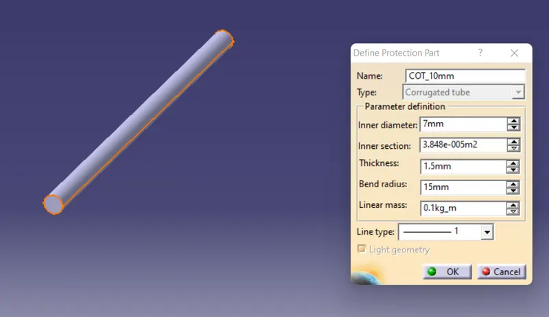
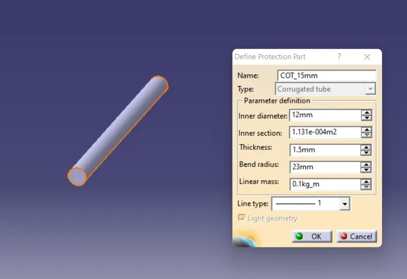
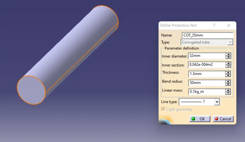
1.open the electrical part workbench and define protection part
enter the required dimensions
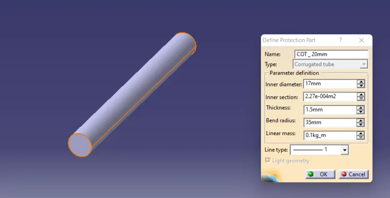
corrogated protection part is created
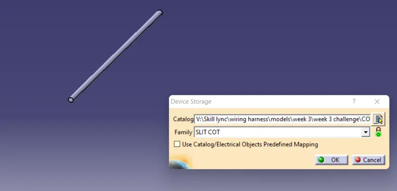
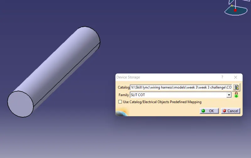
Create a catalog for corrogated tube and add a family of Slit cot and add the diffrent tubes in the catalog
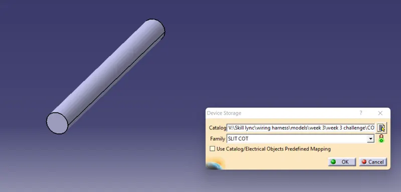
repeat the same for all the given tubes
Corrogated tube - 5mm
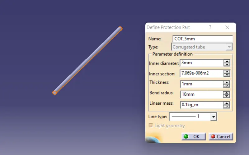
Corrogated tube - 10 mm
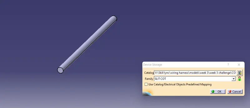
Corrogated tube - 15 mm
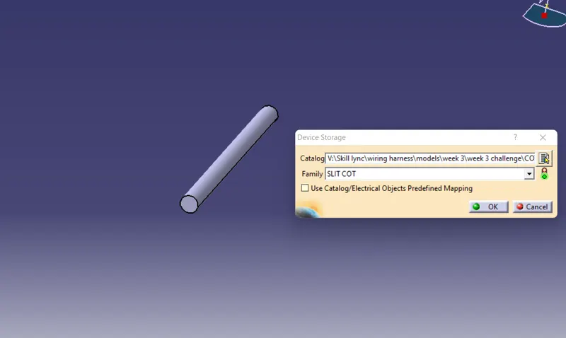
Corrogated tube- 35 mm
Design criteria for wiring harness
- Wiring harness should be routed in such a way that it is easy to assemble on vehicle. Wiring harness topology plays important role to meet these criteria.
- Wiring harness should be routed in a way that it is easy to access in case of service or failure analysis.
- Wiring harness should be secured properly so that it will not get damaged by surrounding component interaction.
- Wiring harness routing should be kept away from Heat Zones like Engine exhaust manifold, Muffler, Silencer, Turbo charger, EGR etc.,
- Wiring harness should be kept away from sharp environment like sheet metal bracket edges, corners, panel edges etc.,
- Ensure that any Human Machine Interactions (HMI) are not causing any damage to harness. Route it away from those areas or protect it properly. Ex. Possible damage in service or during testing/validation (air filters, tail gate openers).
- Wiring harness should be routed in or closed to driver and passenger reach zones like foot zones.
- Wiring harness should be routed away from hoses carrying high pressure fluids like hydraulic oil, brake oil, fuel. If it is routed along with hoses, then positive clamping should be used to ensure enough clearance maintained with hoses.
- Dynamic conditions of vehicle components should not damage wiring harness. Ensure that enough slack is provided to avoid the damage. Ex. Engine rocking during operation, Steering rotation, door hinges, door latches etc.,
- Keep harness away from the components which are subjected to movement during their normal operation like Engine timing belt, ABC pedals, Clutch lever and cables, Steering shaft, Parking brakes, door hinges, door latches etc.,
- Keep harness away from tyre envelope.
- Ensure that harness is not visible or exposed in vehicle. Harness dressing and aesthetic areas shall be taken if it is routed in visible areas.
- Easy accessibility and minimum work to access the service and diagnostic related features which are part of wiring harness supply. Ex. Diagnostic connector, Trailer sockets, Electrical Power Take outs (PTO) etc.
Packaging rules and best practices
- Wiring harness routing shall provide ease in manufacturing, accessibility, easy removal and easy maintenance of attached equipment and wiring harness.
- Routing through small structural holes and openings shall be avoided, to minimize chaffing and handling of the wiring harness during installation.
- Avoid the harness routing and clipping in blind zone of operator during harness assembly or in service.
- Routing shall offer the protection against possible damage through common misuse such as being handhold and temporary support for test equipment.
- Provide additional slack to the harness according to the surrounding and harness bending requirements. If harness is passing through the closures/doors or tail gates, then envelope dimension during opening and closing of doors shall be considered to provide the slack. Check the harness slack requirements with open and close conditions to avoid excess slack.
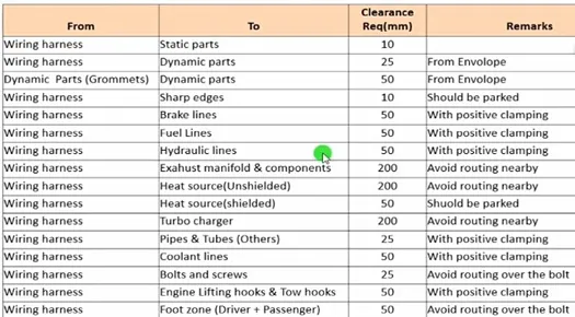
- Ensure that routing meets the clearance requirements with different surrounding parts as described in below table. Any deviation to these requirements shall be discussed and agreed between all stake holders before design releases. Necessary arrangement to protect the harness shall be made in this case.
- Routing Direction:
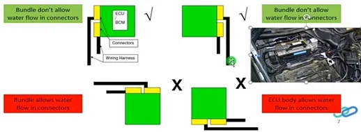
- Ensure that wiring harness bundles not allowing water to flow to the harness connectors or to the grommets. Following care must be taken:
- Keep the wiring harness connectors at height than the harness clipping point. Same point is applicable for grommets as well.
- Drip Loop Creation:
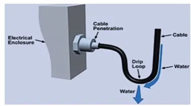
- Formation of Drip Loop has always been a concern which leads to short circuit. Drip loop is a phenomenon where it allows the water to drip and enter the connector cavities or modules.
- When water enters the module or connector cavities, it becomes a major cause for short circuit. Also, if the water gets accumulated inside the tubing because of the drip loop. Wire soaking happens, leading to high chance for short circuit.
- IP Rating – Ingress Protection Rating:
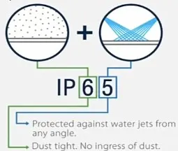
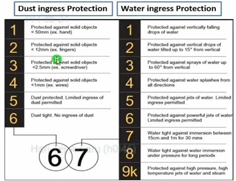
- IP ratings are defined in international standard EN 60529 (British BS EN 60529:1992, European IEC 60509:1989). They are used to define levels of sealing effectiveness of electrical enclosures against intrusion from foreign bodies (tools, dirt etc) and moisture.
- IP rating is defined in following fashion. Two digits are used to indicate the resistance capability to dust ingress and water ingress respectively.
Harness branching rules;
- Branch length should be minimum 50 mm.
- Minimum distance between clip and nearest branching point should be 25 mm.
- Minimum distance between two breakouts should be 50 mm.
- Limit the number of branches from single branching point to 4.
- If there are multiple branches routed from branching point for identical connectors, then connector connection Poka-Yoke should be achieved by harness dressing and managing lengths to avoid incorrect connections.
- Ensure that harness protection is provide according to surrounding temperature, manufacturability and expected reliability.
- Always keep the harness connector at height than harness routing and branching points. This is to ensure that gravity does not allow water entry through harness bundle.
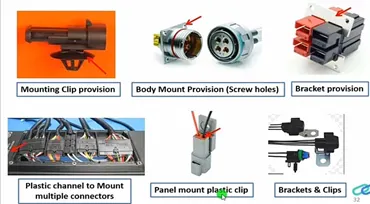
- Use of plastic guiding channels are recommended to meet the clearances in critical areas if it is difficult to achieve by use of clamps. Ex- Inject harness routing on engine.
Thermal Protection Management
There are two aspects in this topic. First is the harness routing management in the high temperature zone and second is the wiring harness protection int eh high temperature zone. Primary input required to decide the routing path and thermal protection is “Thermal Mapping Data” of the vehicle. Skin temperature data of some hoses are also required if harness is routed nearby to them (coolant hose).
Following means can be used to protect the wiring harness in high temperature zones:
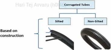
- Use of Corrugated tubes:
- Corrugated flexible tubes also known as Cot tubes / Convoluted Conduits have a wide range of application in automotive industries.
- Corrugated tubes are made from plastic material and they are flexible.
- Selection of corrugated tubes are mainly driven by wiring harness bundle diameter and temperature resistance requirements.
- Black colour tubes are widely used in Automotive and off-road applications but other colours also used to highlight the critical harness for ex. Emission system harness.

.Use of Braided tubes (Nylon woven loom) and Silica sleeves –
- In case corrugated tube is not suitable for the very high temperature zones (Specially in Exhaust area), use of breaded tubes and silica sleeves.

- Specifications:
- Temperature resistance (mentioned in range)
- Bundle diameter
- Abrasion resistance
- Resistance to Hazardous liquids (Petrol, Diesel, Lubricants, grease)
- Resistance to Hazardous gases (Exhaust)
- Resistance to flames
- Colour
- Chaffing protection
- Chaffing is nothing but wiring harness damage due to contact with metallic sharp edges or by any other mechanical means. There is very simple technique to avoid these types of failure
- Clearance management keep harness away from surrounding parts. Specially away from sharp sheet metal edges.
- Use of sufficient and appropriate harness clips. Fix the harness bundle in the areas where it can get in contact with sharp edges. This is the full proof way to avoid the damage.
- Convert the sharp edges into smooth surface by applying rubber beading on it. Not recommended and should be used if above two methods are not feasible.
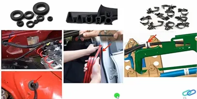
- Use of rubber grommets whenever sharp edge is created due to through holes. Moulded rubber beading is also available to protect round or oval hole edges.
- Vibration protection
- Routing near sharp edge is one of the major risk factors, which contributes to the rupture of wire harness.
- Many times, we forget to take the dynamic conditions and sharp edges into consideration, especially when the harness is mounted on a vibrating object. We can also consider taking an alternate routing path to avoid sharp edges or we can use edge protectors like edge trims, rubber sleeves, Grommets etc.,
- Also, wiring shall not be routed near screws which can puncture the wiring.
- Recommended solution is to keep harness away from this area if possible.
- Typical ex. Of this type of situation is ABS wheel speed sensor cable routing. Wheel speed sensors are mounted on wheel hub and cable is routed through shock absorbers which are quite dynamic in operation and creates lot of vibration with high amplitude.
-
Harness bending basics
Harness bend radius is another important aspect to keep in mind. Bending may be possible in virtual routing but on vehicle it won’t go as shown in 3D. Consider the following points while defining bending radius of harness –
- Bundle diameter
- Type of covering used
- Type of wires used in bundle (insulated thickness does matter)
For silted cot tubes it is recommended to use bend radius minimum 2 times of bundle diameter. However minimum bend radius for different cot tubes sizes can be confirmed with supplier.
Shielded cables (CAN/Sensor), Battery cables (with thicker insulation).
On other hand, excess bend radius shall not turn into excess harness length of wiring harness. This can lead to the fouling with surrounding components and then mechanical damage. Special cares shall be taken for battery cables.
Interconnection connector management
- Whenever there are two or more wiring harness connected to each other, electrical and mechanical joints formed by connectors and called as interconnection. Such a connectors are also called as interconnection connectors or inline connectors.
- Device connectors are always parked with device body. They don’t need addition parking provision.
- However, situation of interconnection connectors are not similar to device connectors.
- Interconnection connectors are not parked with any devices but should be pared with the help of clips/clamps/sheet metal brackets, Plastic brackets etc possible to the packaging conditions
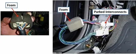
- Un parked connectors can create:
- Rattling noise
- Physical damage to connectors
- Uncontrolled harness routing
- Manual errors during assembly because undefined paring.
- Sometimes use of foam on connectors gives some relaxation from rattling noise and to protect connectors from physical damage
WIRING HARNESS ROUTING OF ENGINE
The engine is taken to route the wiring harness. The engine modeller will provide the dummy connectors at all the locations. First check for all the connector and sensor locations. The present engine has 8 connector location on each side and 2 sensors at each side. The clips, clamps and channels can be used to route the harness with optimal solution.
The components which are connecting to the engine are not part of the geometrical bundle assembly they are going to be part of the context assembly even though they are electrical components.
Steps to be followed
1 .Create a new product file and rename it as Assembly Engine Harness Context
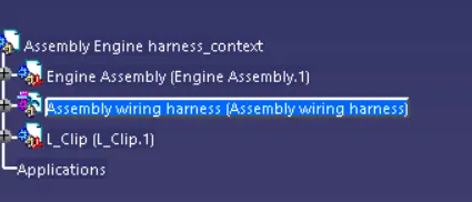
2. Now copy and paste the Engine assembly file to the context assembly.
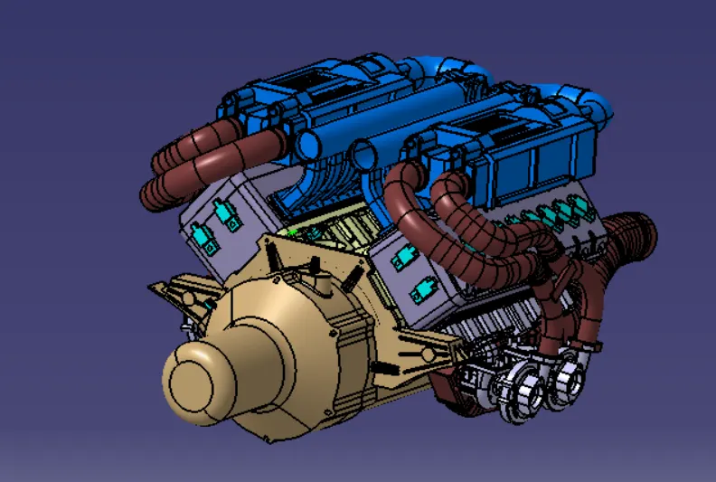
3. Create a new product under context assembly and rename it as Assembly wiring harness
4. Import all the required connectors with electrical properties into the Geometrical bundle.
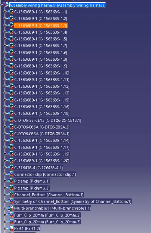
5. Place all the connectors in the specified locations of the engine using snap tools
6.After placing all the connectors, it is required to locate the interconnection connector.
It is advised to use already drilled bolts for placing the interconnection connector and not to drill any holes to the engine exhaust manifold as it leads to damage of the engine.
7. Add sheet metal bracket into the context assembly for interconnector support.
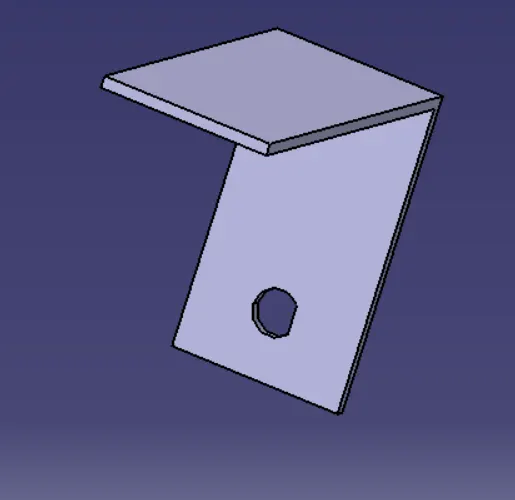
8. Add p-clamps to the context assembly and not to the geometrical bundle assembly because they are fixed at the manufacturing line. If p-clamps are supplied with the wiring harness then it can be part of geometrical bundle assembly.
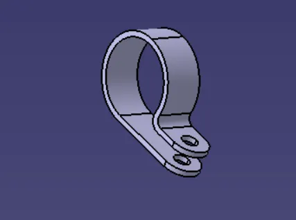
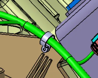
9. Channels can be imported into the wiring harness but a study has to be done on the placement of channel in the correct location without having any extra cut outs and they should be fouling. Define the channel as equipment instead of support. Give all the bundle connection points correctly.
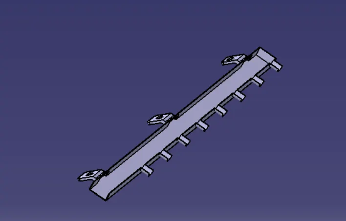
10.Now switch to Electrical harness assembly design.
11.Start the routing. Start from the interconnection connector.
12. Considering all the harness packaging rules, the harness for the engine is routed.
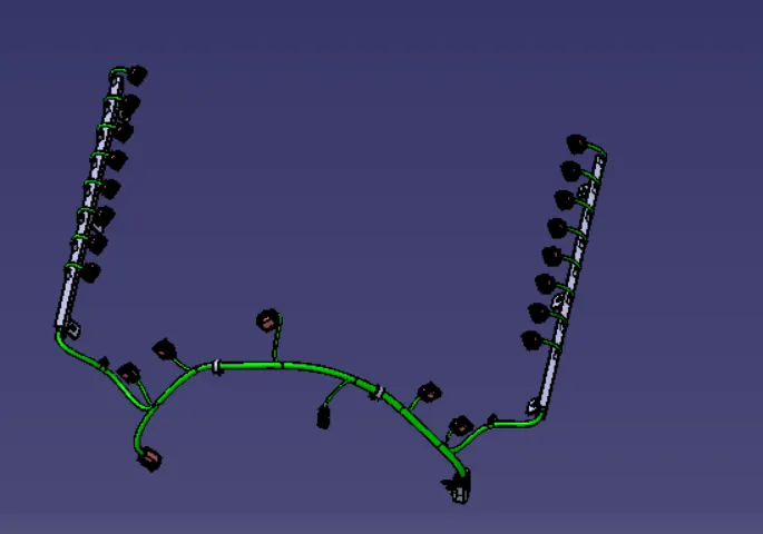
13.Add corrugated tubes for the bundles.
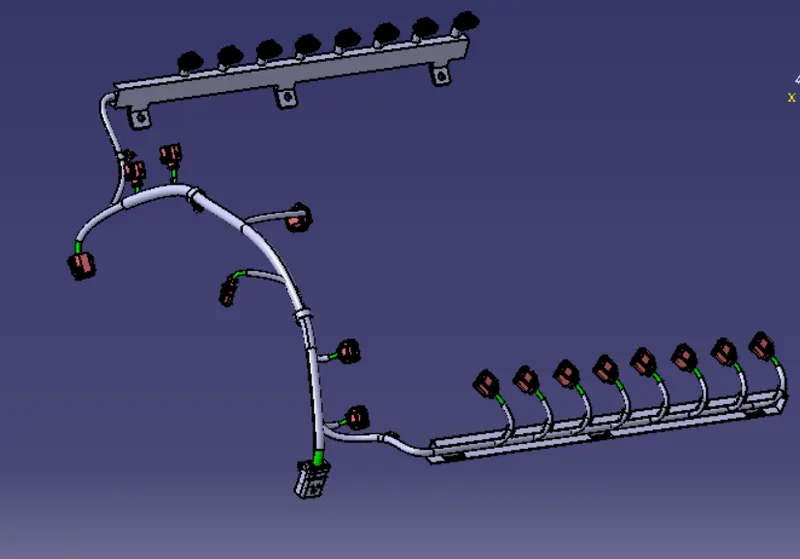
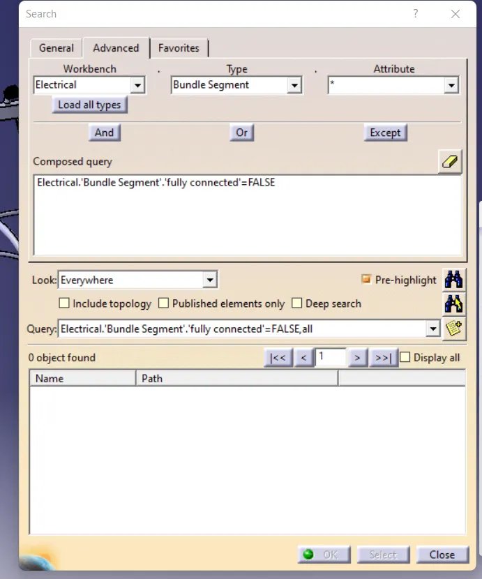
14. Check for bundle continuity. All the bundles are fully connected.
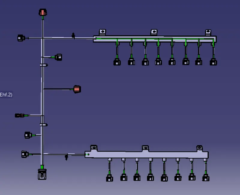
15.Create the electrical flattening of the geometrical bundle assembly.
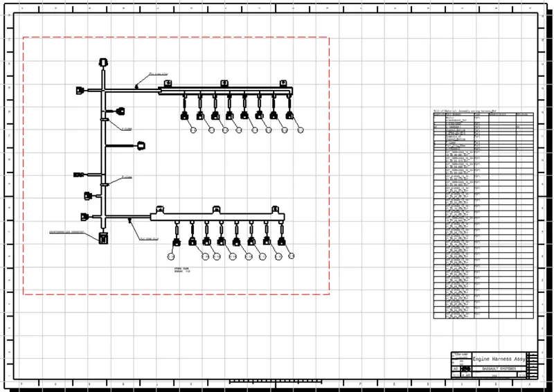
16.Create the 2D drawing file with all the details.
Conclusion
Routed the wiring haress on given Engine and prepared Flatten view drawing by applying all packaging rules and protection covering as required