Week 8 - Challenge 2 - Switch Bezel Design
Objective: Creating the Switch Bezel Plastic component through the given Class-A surface. The tooling axis for the given Class-A Surface to be created meeting the requirements of the draft angle and at the end performing the Draft analysis on the model.
Class A surface of the switch bezel is given for designing the plastic component
Class A surface
It describes the final production surface data for the aesthetic parts
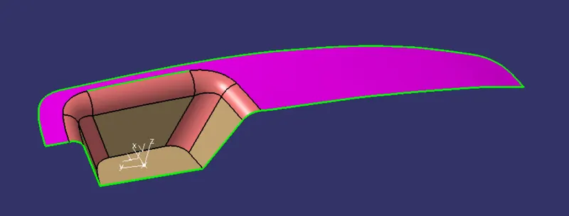
As we can see the A surface have some boundaries inside the surface. By joining the surface we can create a complete class A surface without any boundries inside.
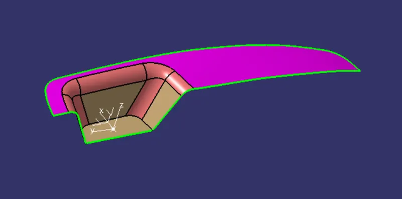
From the given Class A surface a dummy tooling direction is created on the feasible surface. Here i have created the dummy tooling direction on the slope surface and created an intrestion on the surface at tooling axis by creating a sketch. From the sketch obtained at intersection we can check the wall angles which are most parallel to tooling axis and created lines and defined bisecting line for main tooling axis.
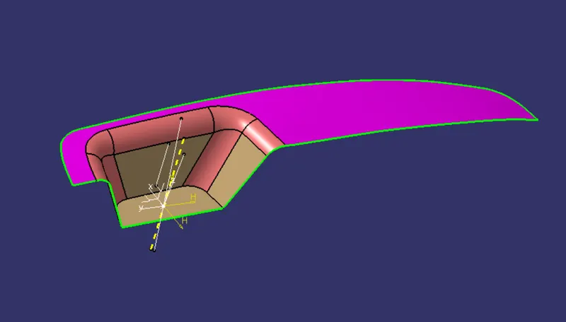
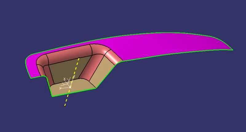
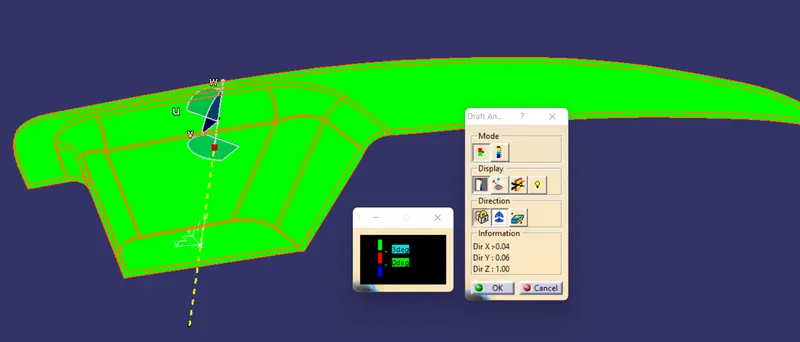
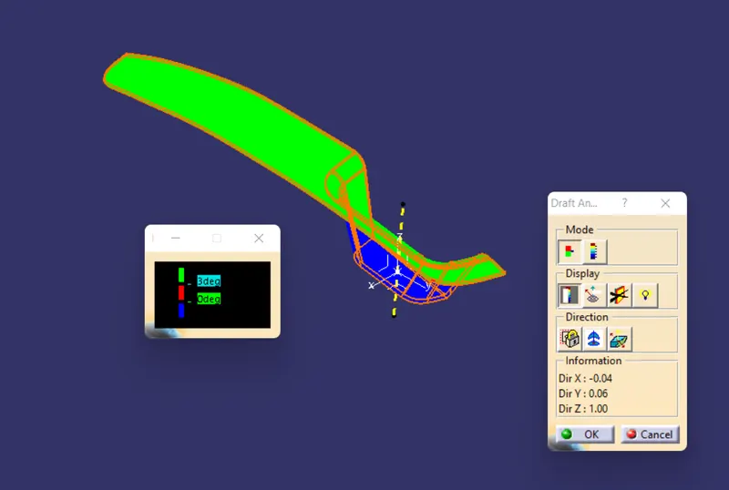
After defining the main tooling axis draft analysis for a postive draft of 3 deg
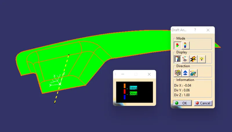
The green colour on the surface represnets that there is no negative draft
Class B surface
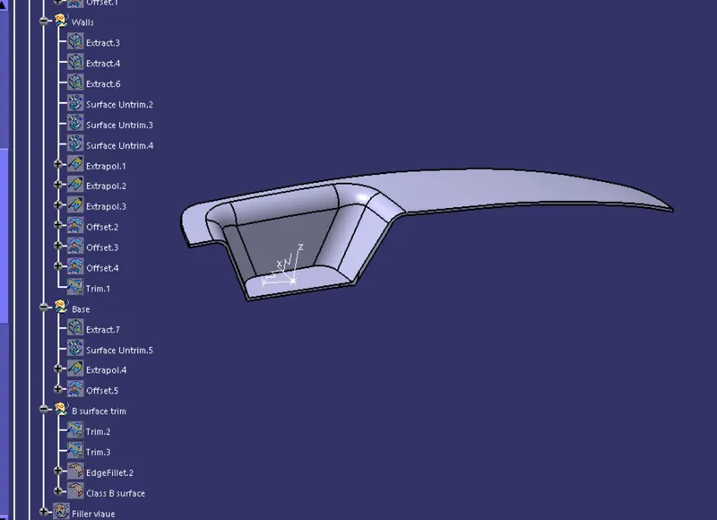
To create the class B surface from Class A we have to Extract the bezel rest surface wall surface and base surface. Untrim the faces and extraporlate the faces so that all the face intersect with each other completly. By trimming the unwanted sides we get th desired shape. And offset by 2.5mm
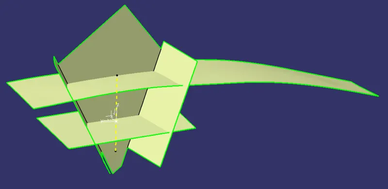
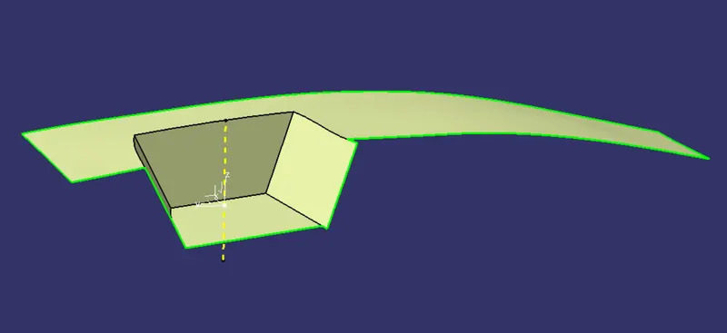
Fillets are given to edges as per the class A surface.
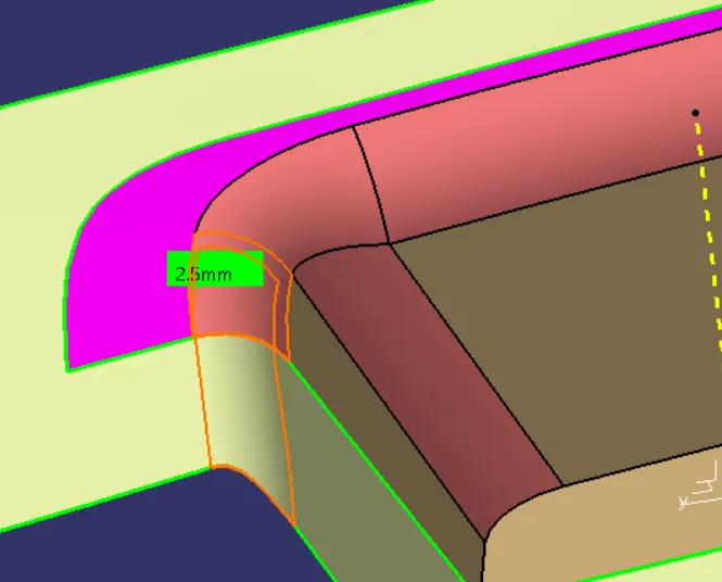
Class B surface is created
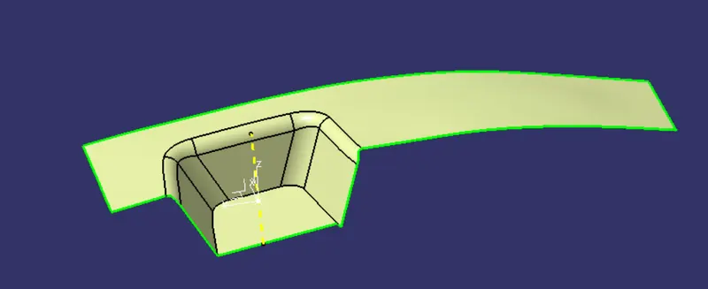
Class C surface
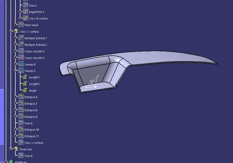
From the class A surface boundry is taken and by using sweep created a class c surface with a positive draft of 3 deg for outer wall. Join the walls and surface by extrapolating and triming the un wanted part
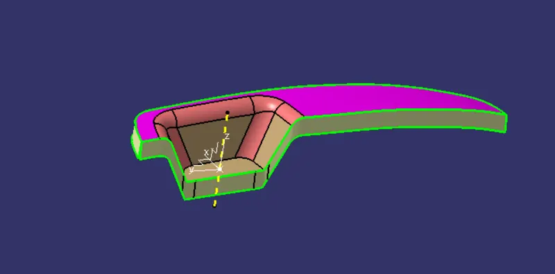
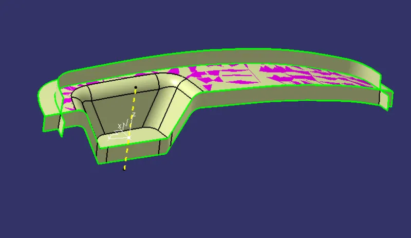
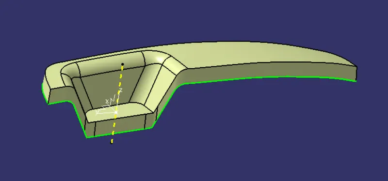
By triming class C surface with class B closed surface is created
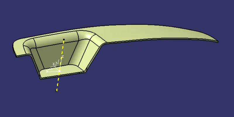
By using closed surface feature we can create a solid body.
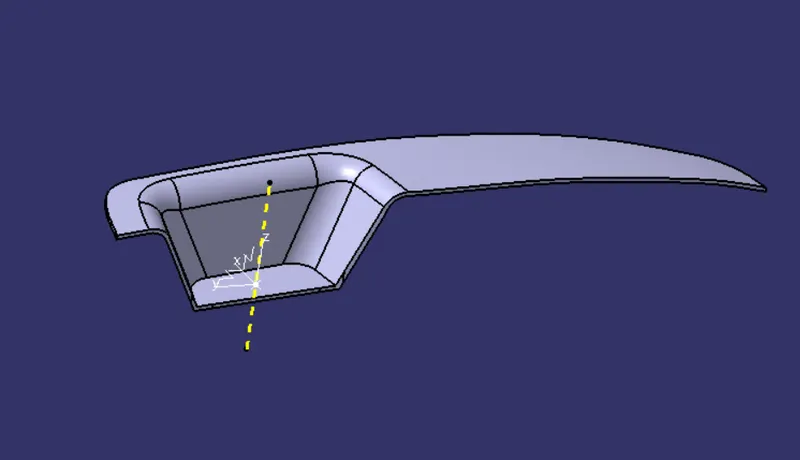
Draft analysis is done for the final closed body
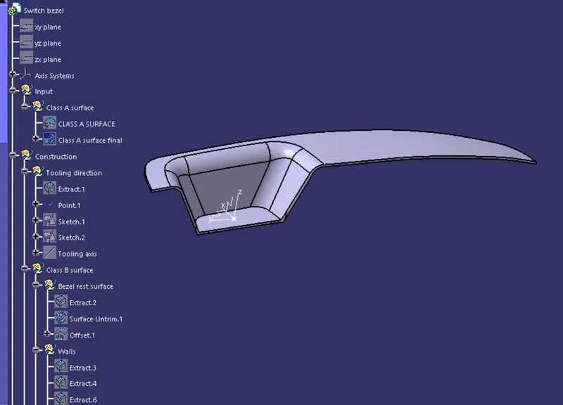
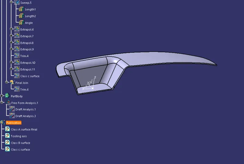
Tree structure of Geometrical set and Part body
solid model with the proper color code of the draft angle in various orientations (Isometric, Front, Side, and Top View)
Isometric View
Front view
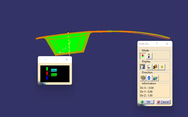
Side view
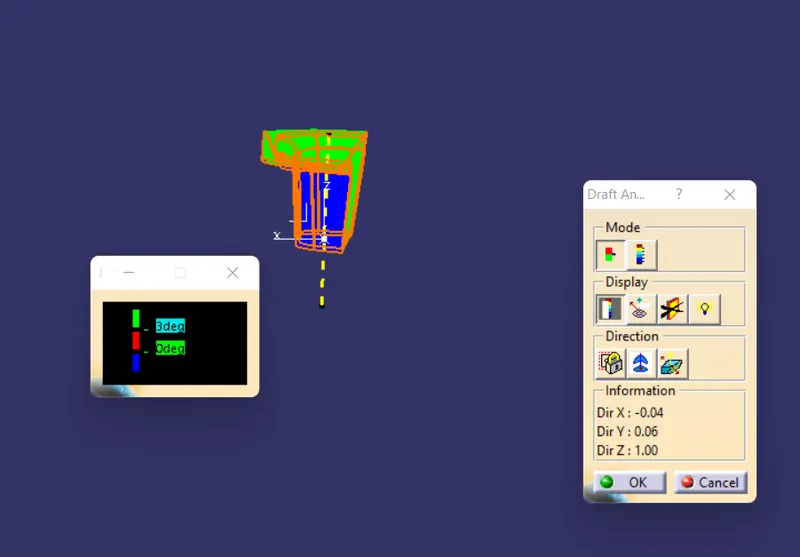
Top View
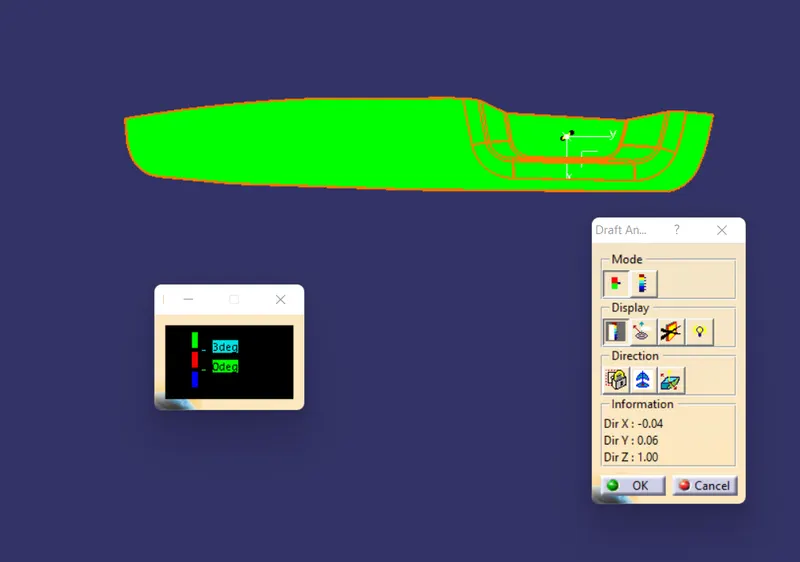
Conclusion : Switch Bezel Plastic component through the given Class-A surface is created . The tooling axis for the given Class-A Surface is created meeting the requirements of the draft angle and at the end performed the Draft analysis on the model. Observed no negative draft and the part meet the manufacturing requirement.