Week 14 challenge
OBJECTIVE:
The main objective of this project is to understand the fundamentals of GD&T and apply them to the design of a butterfly valve using Siemens NX.
METHODOLOGY:
For this project, the entire design, assembly, and drawing creation is done using the Parametric CAD software, Siemens NX. First, each part is designed in NX, and a drawing for each is created after which GD&T is applied to the drawing.
Application of GD&T:
After each part is designed under the application, modeling in NX, the drafting application is chosen to create a drawing for individual parts. After the drawing is created using the required drawing views, proper GD&T is applied as per the requirements of various parts. Application of GD&T in NX is a very simple and effective process because it allows applying any kind of Geometric Tolerancing symbols and tolerances with few clicks. The feature control frame and datums can be applied easily as per the requirement following the standard.
Parts for assembly
All the individual parts designed in NX are described with the process of design, drawing creation, and the application of GD&T.
Body
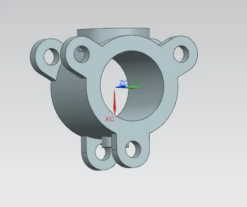
The body is the housing for the internal components and it is the main part of the butterfly valve. The body connects to two pipes on its two sides and it regulates flow. For the creation of this part, simple features like to revolve, extrude, and move objects are used in the modelling application of NX.
Disc/Plate:
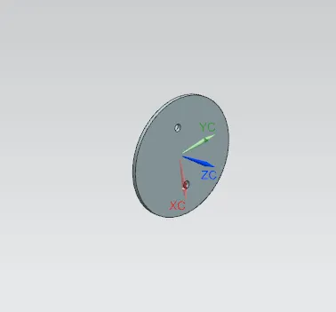
This disc plate is the main component of the butterfly valve which regulates the flow in the valve. The orientation of this disc determines the flow rate of the fluid. It is not perfectly circular, rather it is elliptical in profile. The holes in it help to position it properly on the shaft created earlier. A simple feature like extrude can create this part in NX.
Lever:
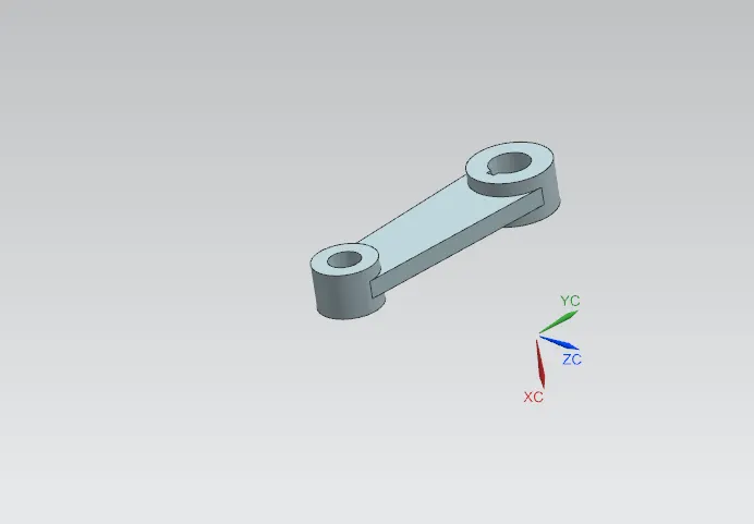
A lever is a handle that is used to rotate in order to regulate the flow. It is attached to the shaft with the help of a key to fixing it in position with respect to it. So when it is rotated, the shaft rotates which in turn rotates the disc and regulates the flow inside the pipe. It is created using simple features like extrude in NX after the proper base sketch is created.
Nut:
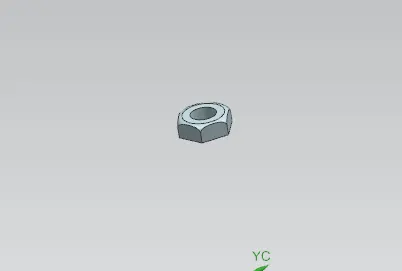
It is the last part that helps to fix the lever in position with the stem. It allows to keep it in position or to disassemble whenever required. It is created using simple extrude and revolve features in NX.
Retainer:
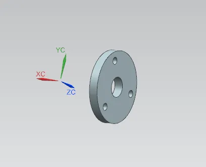
This part helps to retain or to fix the shaft with the body of the butterfly valve. It prevents the shaft from coming out of the body and keeps it in position for the proper functioning of the disc inside the body. The creation of the retainer plate involves only a simple feature like extrude in NX.
Shaft/Stem:
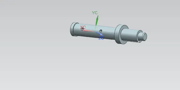
It is another important component of the butterfly valve. It inserts into the body of the valve and sits perpendicular to the direction of flow. It holds the disc inside the body and is clamped with the lever outside the body. It is created using simple features like revolve and extrudes features in the NX modelling environment.
Assembly:
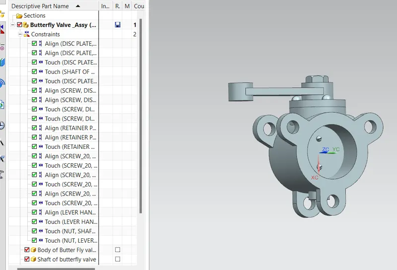
The assembly is created by first placing the body in position and mating other parts to it with the application of different joints provided in NX.
First, the shaft and disc are joined together with the screws in place to create a sub-assembly which is then joined to the body in position.
The retainer plate is then mated with the body and screws are used to fix them.
After that, the lever is mated to the shaft in a position that is then fixed after the nut is mated with the shaft.
Drawing Sheet with GD&T:
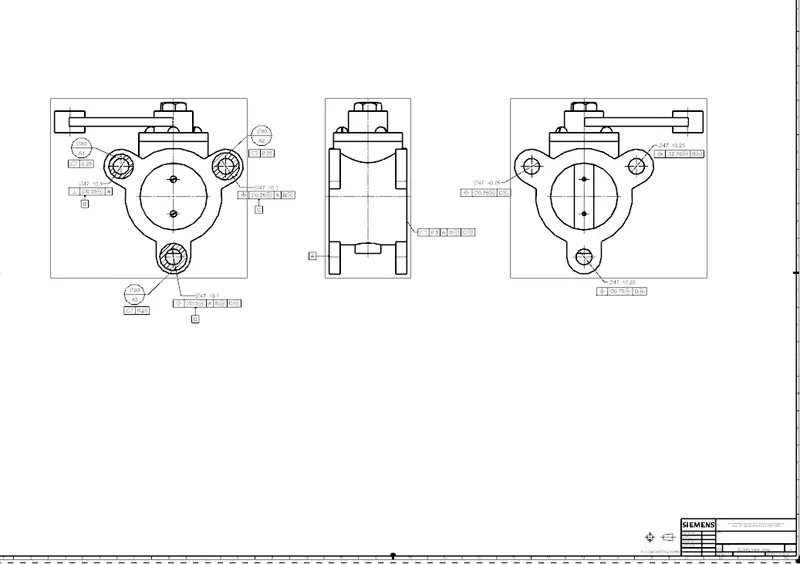
To apply the GD&T to this assembly, we need to apply it to the features which come in contact with the other parts and contribute to the positioning of the valve.
In this case, all the required GD&T for individual parts have been applied already. Now it is applied to the assembly. Here, only the 3 holes on each side of the body come to contact with two pipes. So, the primary datum is defined as the surface containing 3 holes with the application of circular datum targets.
Perpendicular tolerance and position tolerances are applied to the respective holes in order to define secondary and tertiary datum and also a sub-datum D in this case.
As the holes on the other sides should be aligned with the holes on one side, position tolerance is applied to each hole with respect to the datum of the opposite holes.
Flatness tolerance is applied to the primary datum whereas profile tolerance is applied to the other side of the body.