Week 11 - Final project
DESIGN AND DEVELOPMENT OF THE DOOR TRIM PANEL
AIM:
To design and develop vehicle door trim using Catia V5 as a tool with the given Class-A Surface as an input and also design the engineering feature with the help of the Master sections and perform the draft analysis.
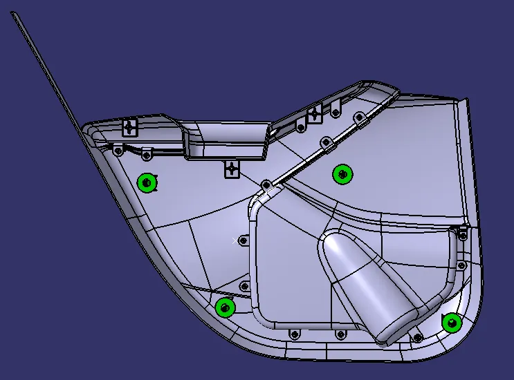
In the project, it consists of four parts of the door trim.
- Arm Rest
- Upper Map Pocket
- Lower Map Pocket
- Lower Substrate
For this, the basic approach to make the plastic model for a given Class-A surface will be
- Creating Tooling and Slider (if required) Axis.
- B surface creation.
- C surface creation.
The following steps are followed for all the door trim parts. At first, we need to check the connectivity of the surfaces and ensure that there is no gap is present between any two surfaces with the help of join and boundary commands. Second thing, we can find the tooling axis of the component. The tooling axis is created in the direction in which the core and cavity open.
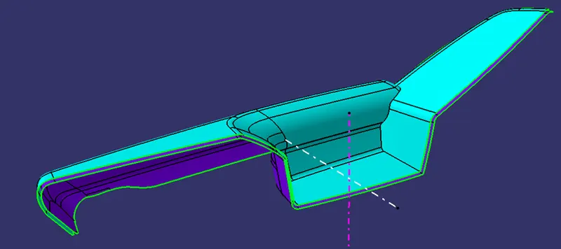
Once we cleared the Class-A Surface then Offset the given Class-A surface to a distance of 2.5 mm to get B Surface. Extracting every surface will be a complex process instead of that, we can directly offset the class-A surface.
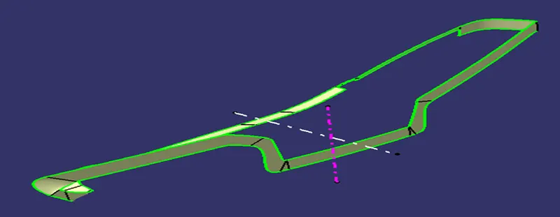
For making Class-C surface, we can use the sweep command with draft direction as tooling axis and the draft value will be 3 degrees. In some cases, it does not work properly. For that, a Class C surface will be created using the sweep with reference surface at 90 degrees and joined with
class A surface and finally trim class B surface to get the final closed surface.
with the help of a close surface option, we can convert the surface body into the solid one.
Design of the Door trim:
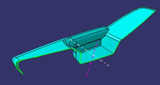
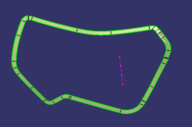
Given Class-A surface of ArmRest.
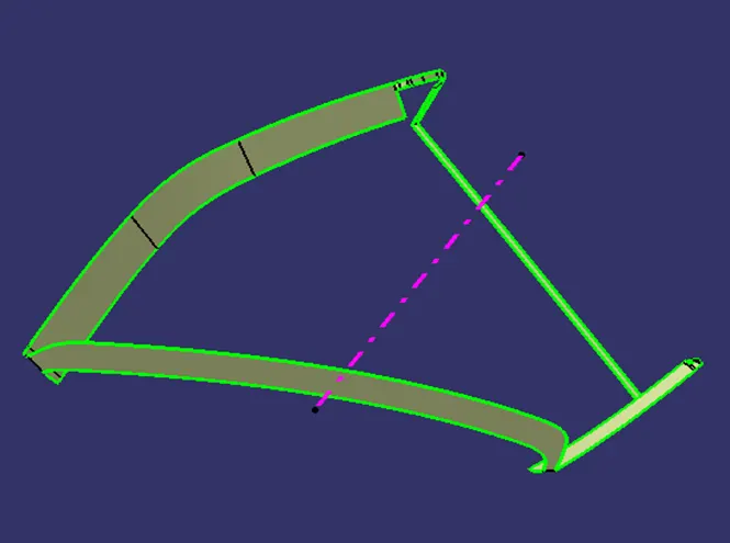
Class B surface offset with a distance of 2.5 mm shown in violet color.
Class C surface will obtain with a sweep with draft direction. In some places, it will be obtained with a reference surface.
Design Rules of Screw Bose:
- Consider the Screw Bose nominal diameter is M6 which is about 2 mm inside diameter
- The Thickness of the Screw Bose is 6*thickness of the component. (0.6*2.5 = 1.5mm). Here it will circular body, hence the 1.5mm is added twice to the inside diameter to get the outside diameter as (5.2 + 3 = 8.2 mm).
- The Draft should be provided as 5 degrees of draft per side to facilitate the part ejection from the mold. If it is more than 1 degree of draft per side, it can lead to excessive thickness reduction and filling problems.
- The Fillet Radius of Rib should be 25mm maximum. If it is increasing, there will be a violation of the 40% thickness requirement.
- The height to the diameter Ratio is 3:1.
Design Rules of Flange:
- The thickness of the flange is the same as the thickness of the plastic component as given in the master section.
- The width of the flange should be 2 to 2.5D, where the D is the diameter of the heat stake.
- The hole in the flange should be given with a clearance of 0.5mm from the heat stake.
*The above design rules are common for all the B Side features in the Car trim.
Draft Analysis of Arm Rest:
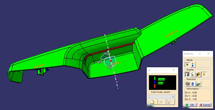
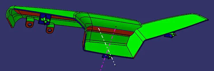
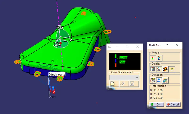
Here some portion is shown in red color, it can be cleared with the slider axis. Once it is done we can go further to design the engineering features and perform the draft analysis for the whole component.
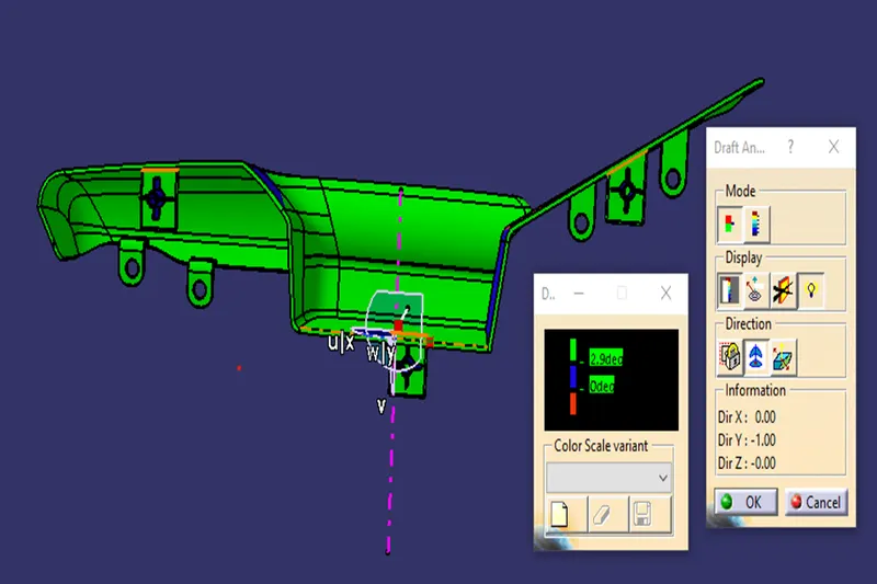
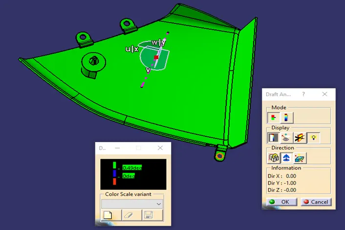
The Nominal draft angle of 3 degrees is provided for every face shown in green color. The Draft angle of 0.5 degrees is provided for the B Side Feature shown in blue color.
Upper Map Pocket:
Class B surface is obtained by an offset with a distance of 2.5mm later it extrapolated the edges to get trim with the Class C surface.
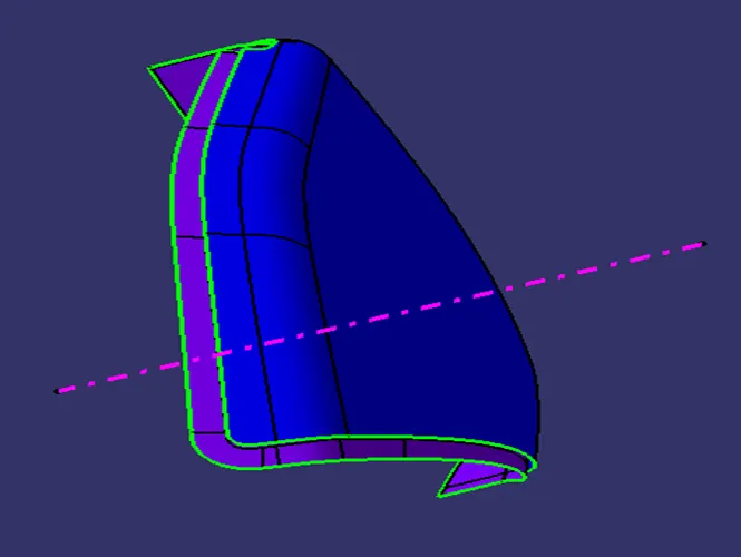
Class C surface is obtained by sweep with draft direction in some places and the other some places with a sweep with the reference surface and join all the sweep surface and get trim with Class B surface and join with Class A.
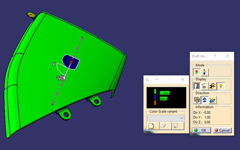
Draft Analysis of the Upper Map Pocket:
A nominal draft of 3 degrees is given on every face.
Draft of 0.5 degrees is given to the B Side Feature.
Lower Map Holder:
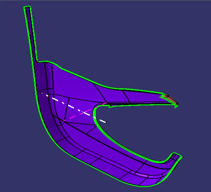
B Surface of the Lower map holder is shown in the violet color. The total class A surface is offset at 2.5 mm.
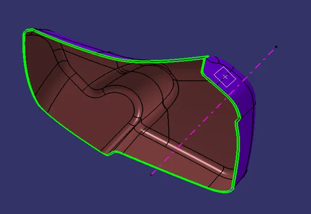
Class C surface is obtained as same as previous one.
Draft Analysis of the Lower Map Pocket:
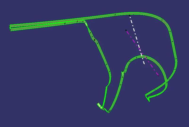
The below blue colored surface shows that as class A surface had a problem in draft analysis, the same thing is continued here and expected result too.
Lower Substrate:
Design Rules of Dog House:
- The Minimum height of the dog house is 6 mm and less than that causes weak steel condition.
- The Minimum width of the Doghouse is 12mm.
- Use the ratio steel width to height is 3:1.
- The Minimum Draft Direction is 1.5 degrees to die drawing.
Design rules of Ribs:
- The Thickness of Rib should be 40% of the component wall thickness to avoid the thick section at the wall base and reducing the amount of retained heat helps to prevent the Sink Marks. (w = 0.4*2.5 = 1mm)
- The Height of the Rib should be the less than and equal to 5 times the thickness of wall components because of the required draft for ejection, the top of tall ribs may become too thin to fill easily. (5*2.5 = 12.5 mm)
- The Draft should be provided as 5 degrees of draft per side to facilitate the part ejection from the mold. If it is more than 1 degree of draft per side, it can lead to excessive rib thickness reduction and filling problems.
- The Minimum thickness of Rib at the tip must be greater than 0.75 mm to provide the fast filling.
- The Fillet Radius of Rib should be 0.25mm maximum. If it is increasing, there will be a violation of the 40% thickness requirement.
- The Ribs should be spaced at a distance is at a Height/Width ratio and 3:1 is suitable. Distance will be considered as Sometimes it will be 2 times the thickness of the component.
- The Rib Root Thickness will not exceed the factor that 30% of the component thickness. It means that it will not cross the value of more than 30 percent of thickness or less than 30 percent of component thickness. (1.3*2.5 = 3.25mm).
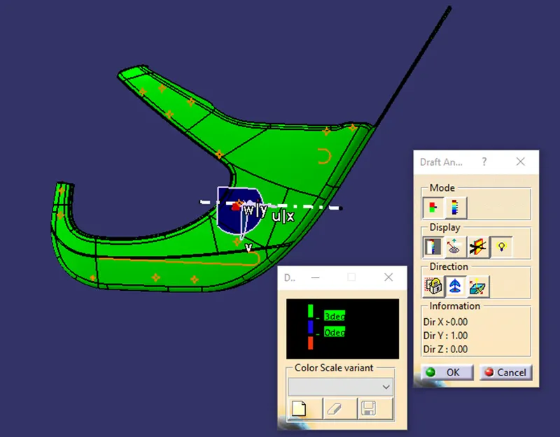
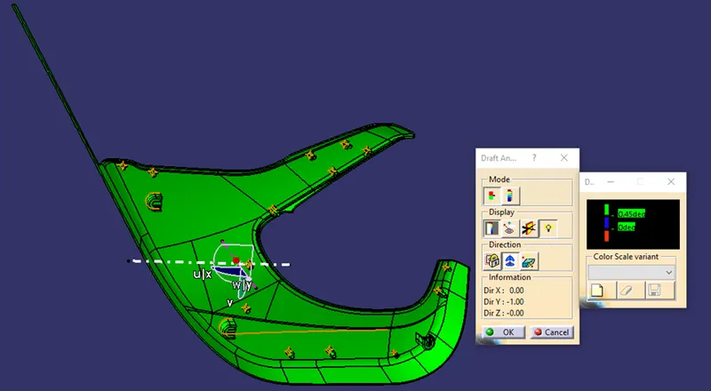
Draft Analysis of Lower Substrate:
Conclusion:
The class B and Class C are created for all parts of the car Trim and B Side Features are also designed and performed the Draft Analysis.