Week 8 - Challenge 5 - Core & Cavity Design
Core and Cavity Design of Switch Bezel
The Report demonstrates the design of core and cavity of plastic component – Switch Bezel using the industry principle such as Parting Surface, Parting line, Tooling axis, Draft Analysis. The molds are designed using surface and solid design techniques in the CAD package Catia V5.
Parting Surface:
- The injection molding consists of two major components: The Movable and the Fixed half.
- During the injection molding process, these two halves are pressed together tightly to form a sealed hollow to avoid the melt flow leakage and maintain a certain amount of holding pressure.
- The Pressed surface is called Parting Surface.
- Usually, the parting Surface is the biggest projection outline of the part.
- The Design of the Parting Surface directly affects the product quality, ease of construction, and operation of the injection mold.
The Design of Parting Surface should follow the principles:
- Design of the mold as simple as possible by avoiding or reducing the side parting to reduce the complexity of mold making.
- Ease of de-molding. The plastic component should stay in the fixed halve of the mold in most cases and be ejected by the ejection system, and avoid the side de-molding action.
- Ensure the dimensional accuracy of the molded parts and try to make the parts with similar dimensional accuracy requirements in the same module to reduce manufacturing and assembly errors.
- Ensure appearance requirement of the molded parts. Flash or Mismatch occurs usually on the parting surface so that the parting surface should not be designed on the class-A surface and it shifted to the class-B surface.
- Ensure adequate Venting. If possible, the parting surface should be placed at the end of the mold flow and it makes a good advantage of filling and venting.
Parting Line:
- It is the intersection line between the parting surface and the plastic component.
- It is the bordered line of the plastic component along the parting surface.
- It is the junction where the core halve and cavity halve meet.
Class-A Surface:
- In Automotive Design, a Class-A surface is any set of free-form surfaces of high efficiency and quality.
- It is the visible aesthetic surface of any automotive component.
- The Class-A surface is done in computer-aided design applications (Alias by Autodesk).
- The Class-A surface modeler is also known as the Digital Sculpture in the industry.
- Class A surfaces can be defined as any surface that has styling intent that is either seen, touched or both.
Class-B Surface:
- Class B surfaces are the engineering surface that is invisible to the eyes or it will be at the backside of the Class A surface.
- These surfaces include the main engineering feature such as Ribs, Screw Bose, Dog house, and Stiffeners.
- It does not contain any aesthetic styling surface texture and content.
Class-C surface:
- Class C surfaces provide the connection between class A and Class B along tooling Axis.
- It contains the draft as per the design requirement.
- It is generally a thickened surface between the Class A and B surfaces.
Tooling Axis:
The tooling axis is the direction in which core and cavity blocks open and draft angles are given with concern to the tooling axis.
Draft Analysis:
- Change the view mode customization to Material mode.
- Go to Insert menu < Analysis < Feature Draft Analysis.
- Click on the compass and align with the main tooling axis to define the new current draft direction.
- Change the draft value to 2.9 degrees and click on the component.
- The target area has shown 3 degrees draft angle. Thus, it clears the criteria of having a suitable draft and the component further will be manufactured.
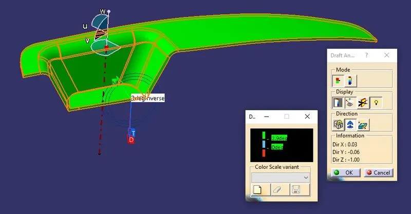
Views of Draft Analysis:
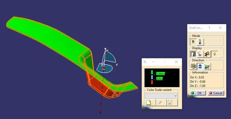
Isometric view- Draft analysis of the Switch bezel component.
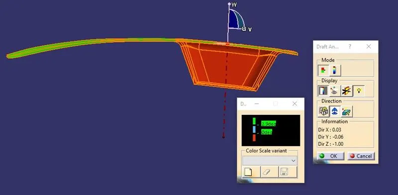
Front view- Draft analysis of the Switch bezel component.
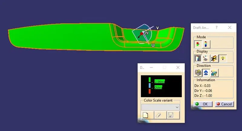
Top view- Draft analysis of the Switch bezel component.
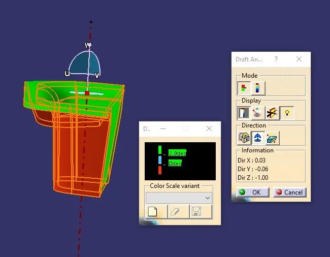
Right side view- Draft analysis of the Switch bezel component.
Creation of Parting Surface And Parting line:
- Using the boundary option, create a boundary line along the edges of the class-A surface, and extrapolate the boundary with a certain distance.
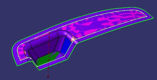
- Unhide the Class C Surface, Trim the Extrapolated surface with the Class C surface.
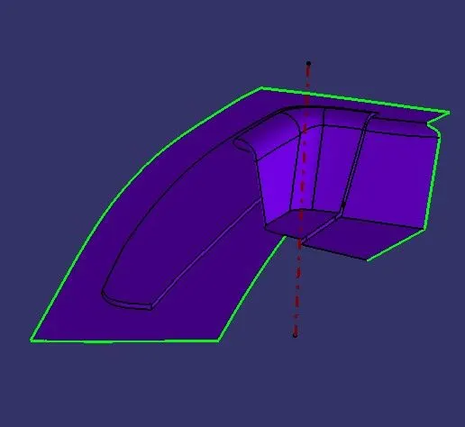
- Unhide Class B Surface, Trim the previous one with Class B surface and we get the parting surface.
- With the help of the intersection option, intersect the parting surface with the component, we get the parting line. It is shown in the Yellow dotted line.
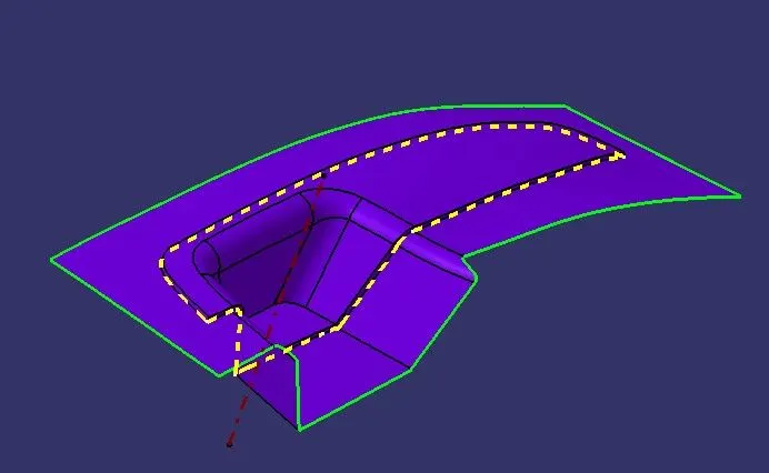
- Using the Split option, we can split the parting surface and the Switch Bezel component with the Parting line as a Cutting tool in the split option.
Creation of Core and Cavity Blocks for the Switch Bezel:
Core Block Creation:
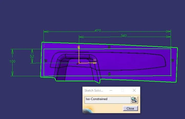
- Draw a Rectangular sketch on the parting surface as shown in the figure.
- Extract the sketch along the tooling direction.
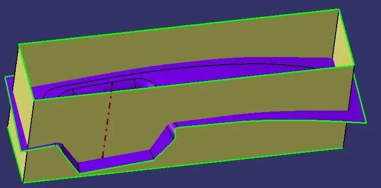
- Trim the extruded surface with the parting surface and apply the fill option to close the upper section and join them together to get the core surface body.
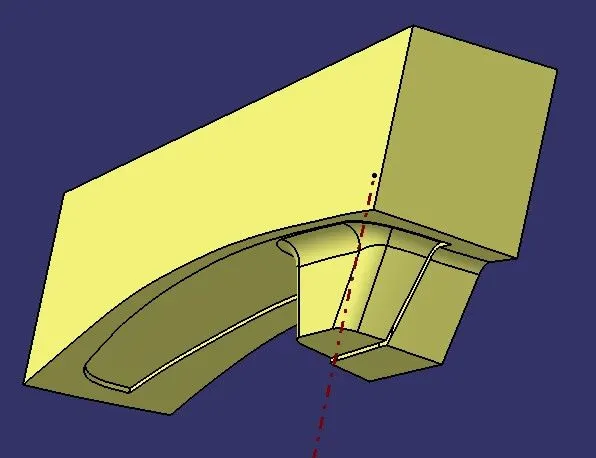
- By switching to part design, the Surface body is converted into a solid body using the close Surface option. Then we will get the Core Block of the Switch Bezel.
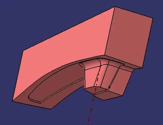
Cavity Block Creation:
- Extrude the previously drawn sketch.
- Trim it with a parting surface and fill the lower section by using the boundary option and joining them together to form the Cavity surface.
- Convert the surface body into a solid body by using the close surface option in part workbench.
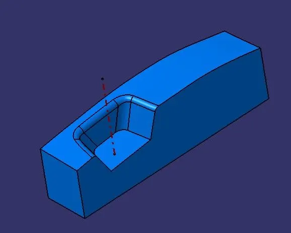
Diagram Representation of Core and Cavity Block:
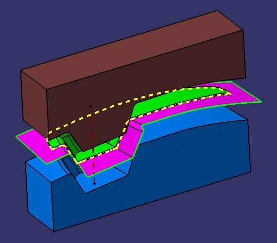
The upper portion shown in Brown color is Core Block and the lower portion shown in the Blue color is Cavity block. The middle portion shown in green is the Plastic component of the Switch Bezel and the Pink color surface is the parting Surface. The Yellow color dotted line is the Parting line. The Vertical Line shown in Red color is the Tooling Axis.
Conclusion:
The design of the Core and the Cavity for the mold of the Switch Bezel is completed using the industrial concept. The draft analysis is performed.