Radar Mast & Final Assembly of Yacht
Modeling of Sunseeker
Predator Yacht
Objective:
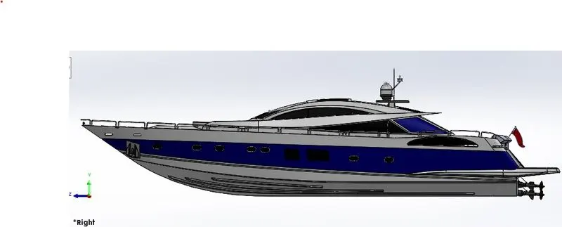
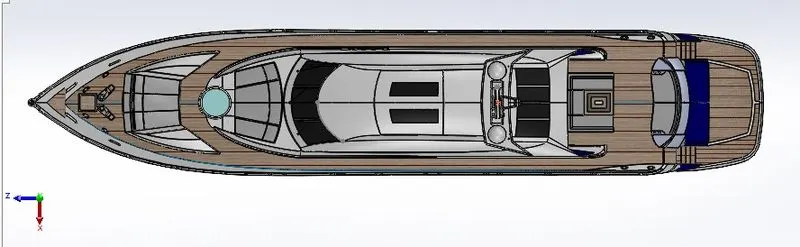
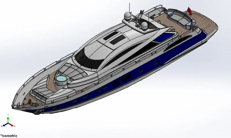
In this project, the objective is to Model the Individual part of the Yacht and assembly it, by using features on SolidWorks and to create a photo-realistic model by importing CAD data and create stunning imagery in an intelligent environment using SolidWorks visualize.
Introduction:
This project explains the modeling of each part and makes it into an assembly of Yacht using features in SolidWorks. It also explains the rendering of the model using SolidWorks Visualize helps us to generate Photo-realistic images.
Design Methodology:
Description of Tool/Feature
The various modeling features used for modeling the American chopper are discussed below
Extrude base\boss:
Extrusion is a method of defining three-dimensional geometry by translating a two-dimensional sketch normal to the sketch plane, for a predefined distance or up to a specified reference. Use the Extrude base\boss tool to create a solid or surface feature, and to add material. First, we have to draw a closed 2d Sketch then make that into extruding the feature by defining depth value. The depth should be given from the reference Sketch or edge.
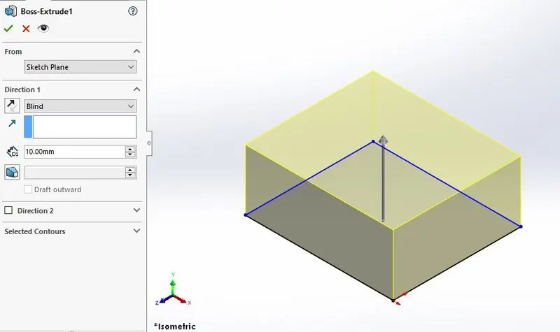
Fig.1. Extrude base\boss feature.
Cut Extrude:
This feature is similar to the Extrude base except one thing is that removes material from the body instead of adding it. Here the sketches are to be drawn on the body and cut to a specified length.
Mirror:
Mirroring is another way that SolidWorks can create a “copy” of an existing object. Additionally, we must choose a plane to mirror parts. In most cases, you will have to create own plane or sketch to have the mirror done the way what we need. The ability to mirror can be found in part and assembly files, and allows you to mirror sketch entities, features, faces, bodies, and components. There are two mirror functions available while working with 2D sketches, mirror entities, and dynamic mirror. Both allow you to mirror parts of a sketch about a straight line.
Mirroring of part or 2d sketch can be done derived from the Original version, it projects the sketch on the opposite side of an existing one about the center line. Dimensions can be added before or after the mirror depending on preference.
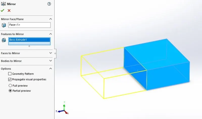
Fig.2. Mirror Feature.
Revolve:
To create revolve in SolidWorks, you need a sketch from which revolve can be created as well as an axis for this sketch to be revolved around. The first thing to understand is what the sketch profile should look like to create revolve. The revolving feature involves the spinning of a 2D profile around the axis of revolution and converts it into the 3D Profile. The axis can sketch, edge of the existing feature. The Revolve feature is defined by the angle of rotation.
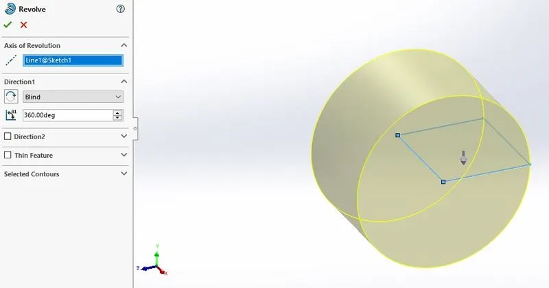
Fig.3. Revolve.
Sweep:
A Sweep is a tool that creates a solid, surface feature by moving a profile along a path. First, define the sweep profile then define the sweep path SolidWorks offers three different types of sweep profiles: sketch, circular and solid. To create a solid, use the Swept Boss tool to move a profile along a path. The profile can contain one or more closed contours. If the profile is circular, the new Circular Profile option only requires a path to be sketched.
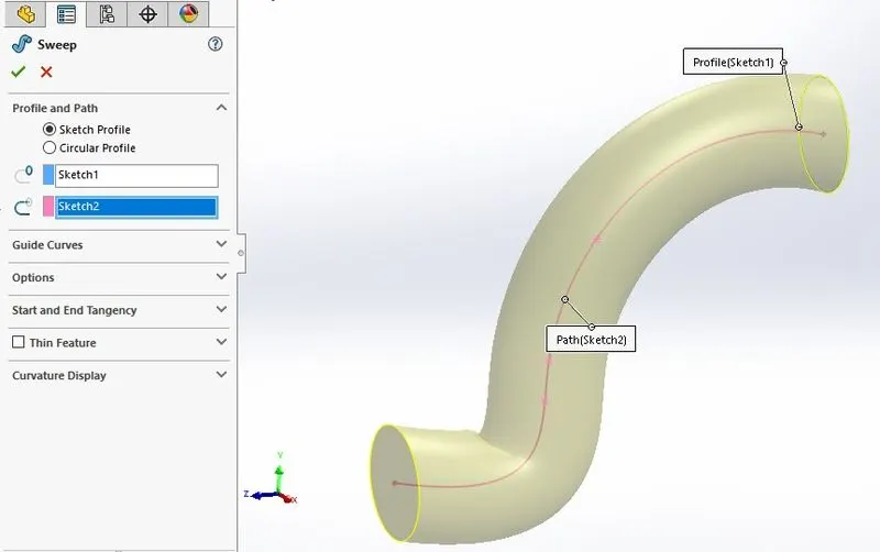
Fig.4. Sweep Feature
Fillet:
The Fillet is a common feature which is rounding of an interior and exterior corner or face of a part design. It can be created by selected an edge of a part and define it by radius, type, and location.
The option for “Tangent propagation” is one of the most powerful and useful options included in the Fillet feature. With this option selected, you can choose to create a single fillet, and any tangent edges or tangent faces that this fillet encounters will automatically become filleted as well. This can be a huge time saver, as it often omits the need to select these additional edges or faces. When the toggle tangent propagation is ON, it observes that any tangent edge from the original edge encounters is automatically filleted with the same value as the original edge. Otherwise, it should be select the single edge for fillet.
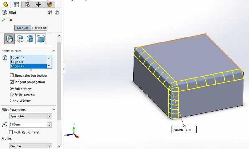
Fig.5. Fillet Feature.
Chamfer:
The chamfer is a transitional edge between two faces of the part. It can be used to remove to a sharp edge and make into the sloped edge by defining with distance and angle of the chamfer. Here the tangent propagation helps to identify the tangent edges or tangent faces that this Chamfer encounters will automatically become chamfered as well. It can be created by selected an edge of a part and define it by distance, angle depend upon the selected Chamfer type.
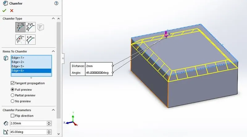
Fig.6. Chamfer feature.
Shell:
The Shell command allows you to define a wall thickness and automatically hollow the part while allowing faces to be removed as needed. If no faces are specified to be removed during a Shell feature, the part will be hollow, but this can only be seen by creating a cross-section of the part. Access the Features tab of the Command Manager and activate the Shell command. The first input allows the wall thickness to be specified. The second selection allows specified faces to be removed from the model.
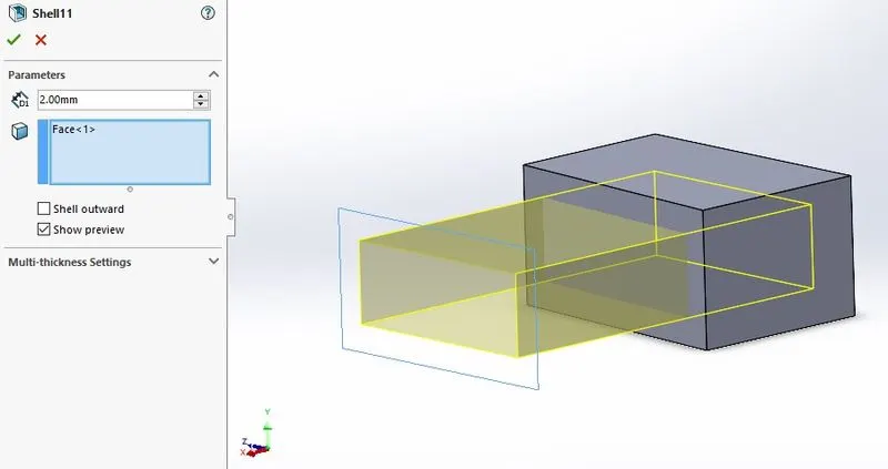
Fig.7. Shell Feature.
Linear and Circular pattern:
Pattern commands are a designer’s best friend in terms of replication and improving overall efficiency. This offers a great amount of flexibility in terms of placing the features. Linear and Circular driven patterns are all common commands used by the everyday CAD user. The tool will be enabled by defining the number of instances and distance or angle.
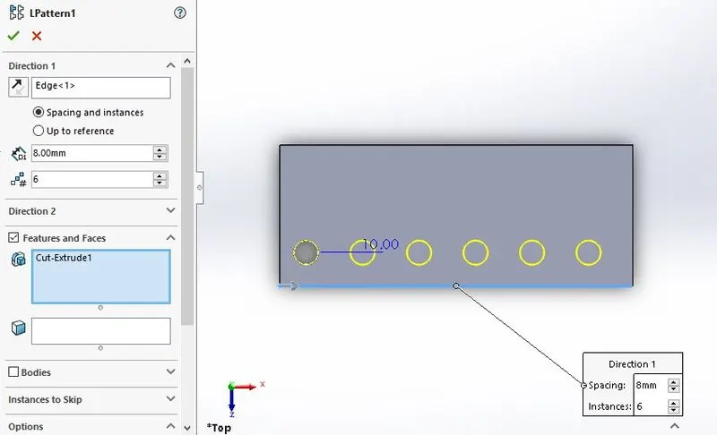
Fig.8. linear Pattern Feature
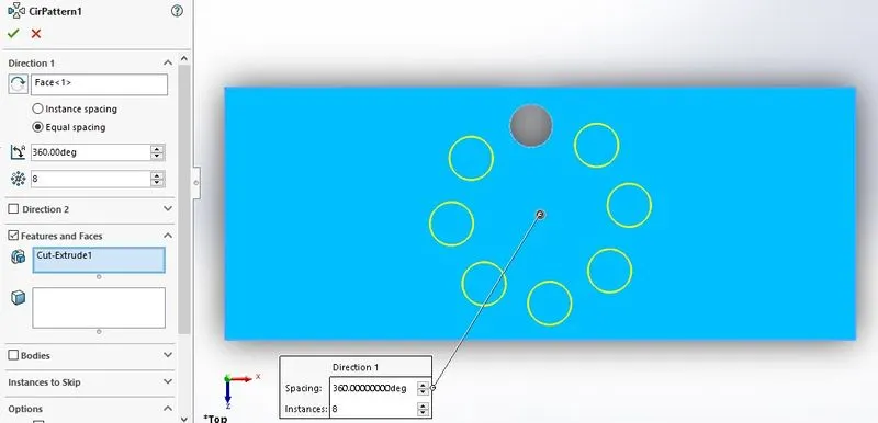
Fig.9. Circular pattern Feature
Projected Curve:
Using the tool, to create a 3D curve with help of two 2D curves which are drawn on an intersecting plane. Align the sketch profile such that when they are projected normal to their sketch plane; the implied surfaces will intersect, creating the required result. It helps us in designing the complex surface model.
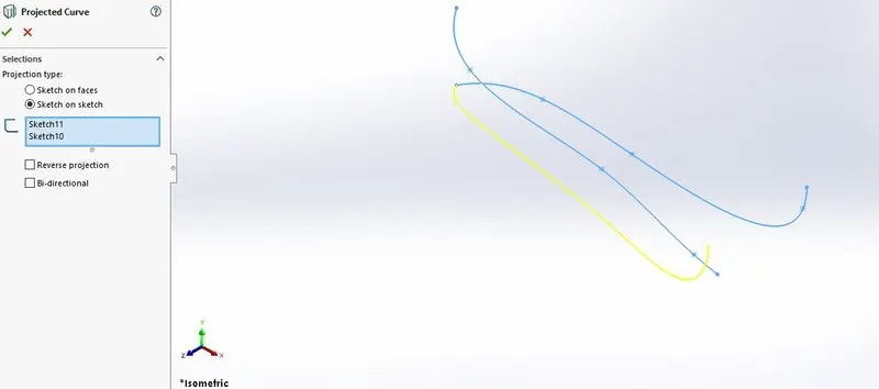
Fig.10. Projected curved
Mates:
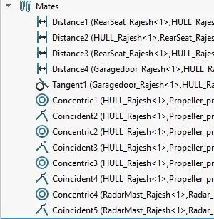
When we create a part in SolidWorks, the position of each body is defined in x, y, z space. When we create an assembly, we use Mates to define components relative to each other. The first part should be fixed in space, which saves us several Mates at the outset. The next should be defined relative to the first, and subsequent Mates defined relative to the already mated geometry. To restrict the movement, by keeping the number of degrees of freedom for movement in the assembly to a minimum. Some of the mates are used in this project are coincidence, tangent, parallel, perpendicular.
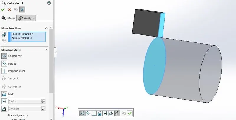
Fig.11. Mate in the Assembly part.
Ruled surface:
A ruled surface is a surface where every point on a surface has a straight line that passes through it and lies on the surface. It can be enabled by selecting any edge and then apply the ruled surface feature option.
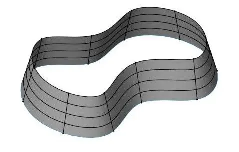
Fig.12. Ruled surface.
Surface knit:
Knit surface is the most commonly used feature in creating a solid body in SOLIDWORKS. Use the Knit Surface tool to combine two or more faces and surfaces into one. Edges of the surfaces must be adjacent and not overlapping for the knitting. By selecting the “create solid” checkbox from the top of the knit surface Property Manager. For this option to be enabled, you must select the surfaces first and make sure that these surfaces are enclosed or form a closed volume.
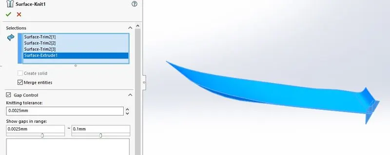
Fig.13.Surface knit.
Surface trim:
The trim surface feature can be used as a trim tool to trim intersecting surfaces from two or more surfaces. To create a solid body, you must select mutual under trim type in Property Manager. Creating a solid body in trim surface feature is a little bit tricky. You can follow these steps to create a solid body. First, select the surface as trim tool and surface to trim under trimming surfaces of selections. Second, you can choose “keep selections” to select fewer surfaces or choose “remove selections” which requires more surfaces to select. Third, select the surfaces you want to keep under “pieces to keep”.
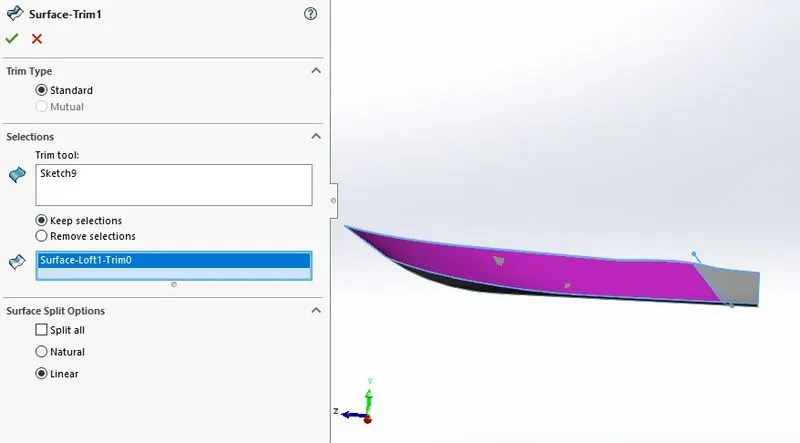
Fig.14. Surface Trim.
Surface loft:
Loft surface is the surfaces generated by the multiple 3D curves or Existing edges create a smooth Tangency between the selected surface. The sketches are drawn in a different plane which can be perpendicular to each other. Guide curves are created, if necessary.
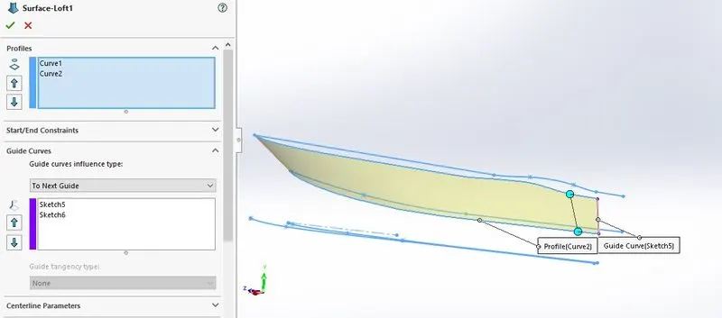
Fig.15. Surface loft.
Surface fill:
You can use this feature to construct a surface to fill a gap in a model. Create a solid. Include features as separate entities, or merge those features. The real strength of the Fill surface is to fill irregular patches.
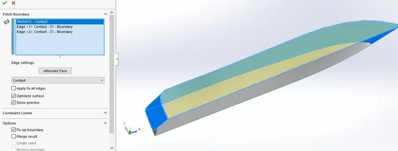
Fig.16. Surface Fill.
Description of model:
Hull:
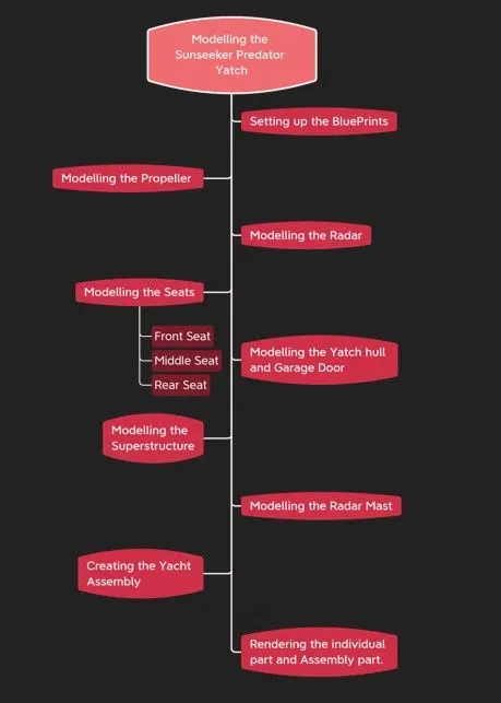
A hull is the watertight body of a Yacht. The hull may open fully or partially covered with the deck. On the deck, a Superstructure is assembled. At first, the half portion of the hull is to be modeled and the next half portion will obtain by mirror the existing one. The sketch is drawn by Blueprints as a reference. Appling, the knit surface to make the surface join and later help us form a solid body.
At first, we have to import the blueprints of the hull. The modeling starts with the projected curve of two sketches and surface loft to make the side and lower portion of the hull. The upper portion of the hull is modeled by applying the fill feature and the knit the surfaces and, to that and apply the shell feature. Windows are modeled by using the Extrude cut, linear, and fillet. The Porthole and Anchor hole are modeled by straight slot, Extrude cut, solid sweep. Staircase by extruding. The Railing is modeled by using a projected curve, solid sweep, and reference plane and the remaining extended portion can be deleted by the delete face feature. Anchor is done by extruding, Extrude base\boss cut, fillet, chamfer, and mirror. Trim tabs are done by extruding, fillet, revolve, and revolve cut. The mirror Feature is applied to get another half portion of the hull and make it combine as one part.
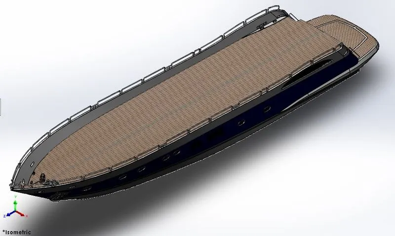
Fig.17. HULL.
Superstructure:
A superstructure is a decked structure on the freeboard deck, extending from side to side of the ship.
At first, We need to import the blueprints and, then import the deck surface created in the hull part by selecting only the surface option for reference to the remaining part. The half portion of the Superstructure is to be modeled and the next half portion will obtain by mirror the existing one. The sketch is drawn by taking the Blueprints as a reference. Appling, the knit surface to make the surface join and later help us form a solid body.
The Side part of the Superstructure is done by surface Extrude base\boss and ruled surface and projected curve, surface loft, surface sweep, surface fill, and knit the surface. The side window portion can be done by spline and surface loft. The upper portion and front portion of glass will be done by the surface loft and knit. The rear portion of the superstructure is done by the surface loft and ruled surface. The Jacuzzi bath is done by Extrude base\boss, Extrude cut, and the fillet. The knit is applied to surfaces and helps to make the knitted surfaces into a solid body. The supports are done by the solid sweep and a reference plane. The upper windows (sunroof ) are done by cut extrude and Extrude base\boss. The other portion of the part can be obtained by the mirror. The wipers are done by Extrude base\boss, Extrude base\boss cut, chamfer, and fillet.
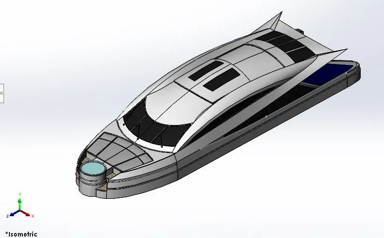
Fig.18. Superstructure.
Seats:
The Yacht consists of three seats. They are Front, Middle and, Rear seats.
At first, We need to import the blueprints and, then import the deck surface created in the hull part by selecting only the surface option for reference to the remaining part. This step is repeated for all the seats.
The front seat is done by the surface loft, surface Extrude base\boss, surface fill, revolve, and fillet. The remaining half portion is obtained by mirror the existing one. The fillet is to be applied to edges to round over the edges.
The middle seat is done the Extrude base\boss and fillet. The remaining half portion is obtained by the mirror.
The rear seat is done by surface sweep, surface Extrude base\boss, surface loft, and ruled surface. then the surface is to knit. The remaining portion is to be trim. The other part can be obtained by mirroring the existing one
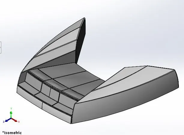
Fig.19. Front Seat.
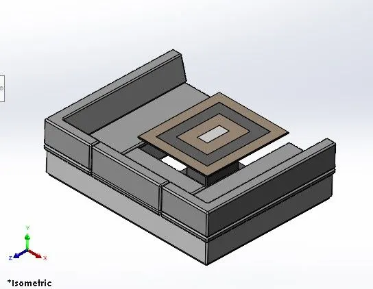
Fig.20. Middle Seat.
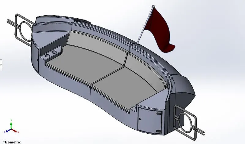
Fig.21. Rear Seat.
Propeller:
A propeller is a rotating fan-like structure that is used to propel the ship by using the power generated and transmitted by the main engine of the ship. A ship can be fitted with one, two, and rarely three propellers depending upon the speed.
The propeller is done by revolve, solid loft, fillet. The blade can be obtained by a circular pattern. Fillet is to be given to the edge.
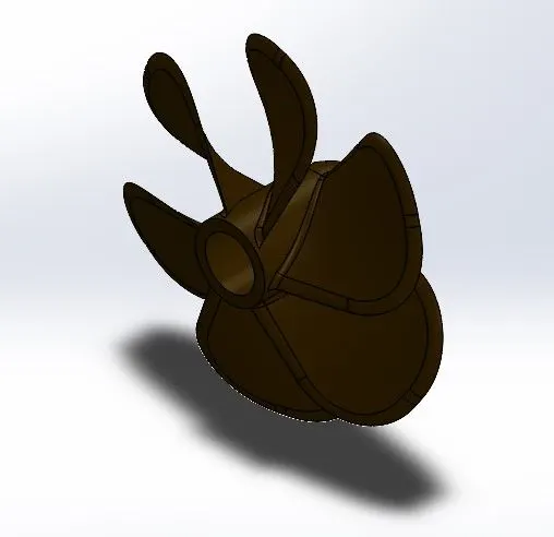
Fig.22. Propeller.
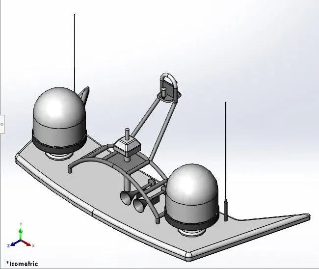
RadarMast:
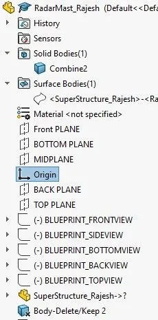
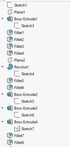
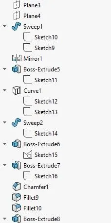
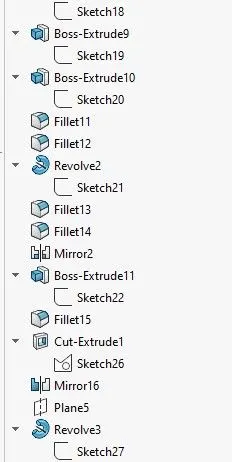
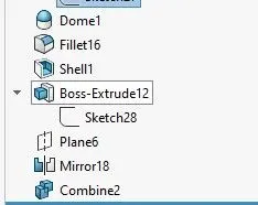
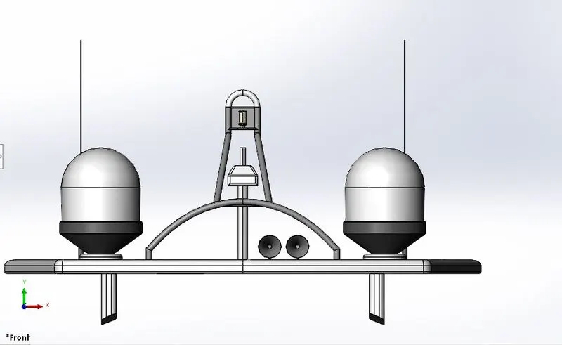
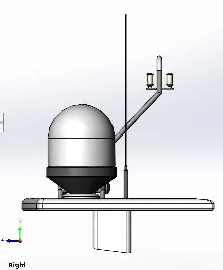
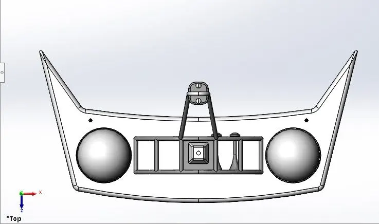
It can be done by extrude, revolve, fillet. The half portion is done first and later it mirror to get another portion of part.
Fig.23.Radar Mast.
Radar:
Radio Detection and Ranging, is used to detect an object and its position relative to your current location. It helps in detecting boats, birds, landmasses, and weather conditions, even if the visibility is less than usual. It can be done easily by the Extrude base\boss, Extrude base\boss cut, and fillet.
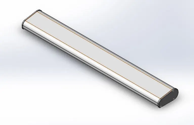
Fig.24. Radar.
Garage door:
The Garage door can be open either by manually or by an electric motor. They are large enough to accommodate the vehicle. It can be done by the Extrude base\boss, Extrude base\boss cut, and fillet.
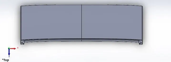
Fig.24. Garage door.
Assembly of Yacht:
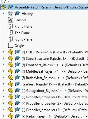
An assembly opens with the Insert part Property Manager active. Click in the graphics box to add the part to the assembly. SolidWorks makes the First component fixed automatically.
All the part models are imported into assembly parts and to make an assembly. Firstly the Hull part is to be placed and it is automatically fixed. These steps were repeated for the following three parts Seats such as Front Seat, Middle Seat, and Rear Seat, and Radar Mast and Radar. The propeller is inserted in the down part of the hull and provides for perfect alignment mate. The mating feature is provided for perfect alignment or relocate the geometrical relationship with the Hull.
Fig.25. Assembly of Yacht.
Rendering:
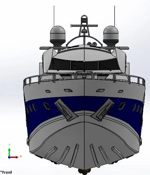
In this Rendering process, the Yacht was set up in such a way that looks natural and unique. Decals are added to the body parts. Viewpoints and camera direction are changed. With the help of SolidWorks visualize, the scene and the appearance has made changes. The final rendering was done to make the Predator Yacht, realistic and digital.
Creating 3D renders has many benefits to your business. Not only can you produce great visual content during the development stage to kick-start your marketing and sales teams, but it can also be a very powerful aid during tenders. A high-quality photo-realistic image can help potential customers and decision-makers buy into your design from the beginning.

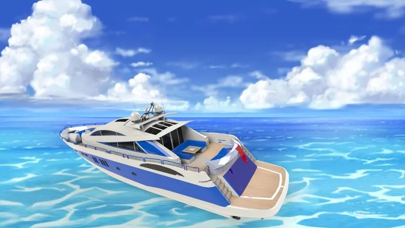
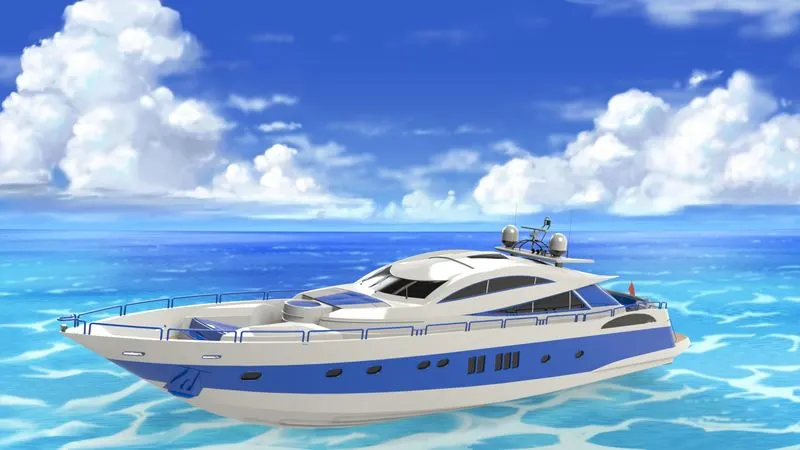
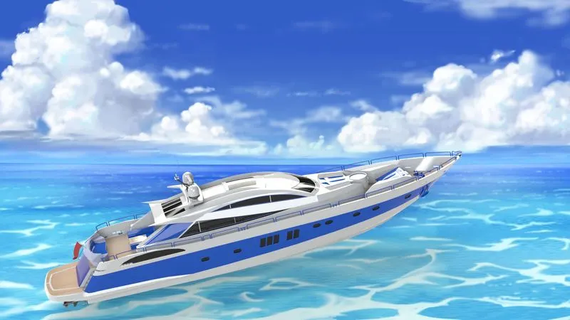
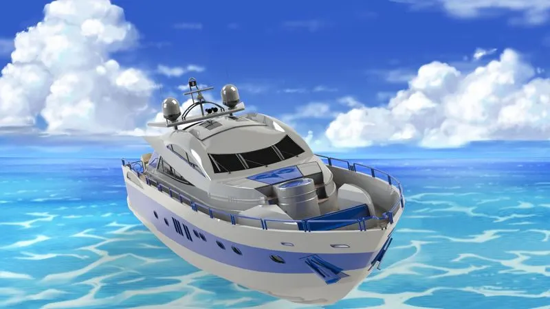
Fig.26. Rendering Images.
Conclusion:
In the project, The Individual part of Predator Yacht was modeled by using Feature on Solid Work. The Drawn sketches should be given with proper Constrained with dimensional and geometrical. Decals and Appearances were added to the respected body. Then the individual part are assembled by using the feature on SolidWorks. The environment and scene were imported to make a Predator Yacht look Realistic and digital.