Photo Realistic Rendering
SKILL-LYNC
MODELLING OF
AMERICAN CHOPPER
ON SOLID WORKS.
By
Durgasi Rajesh
Objective:
In this project, the objective is to Model the Individual part of American Chopper and assembly it, by using features on SolidWorks and to create a photo-realistic model using SolidWorks visualize.
Introduction:
This project explains the modeling of each part and makes it into an assembly of Chopper using features in SolidWorks. It also explains the rendering of the model using SolidWorks Visualize helps us to generate Photo-realistic images.
Design methodology:
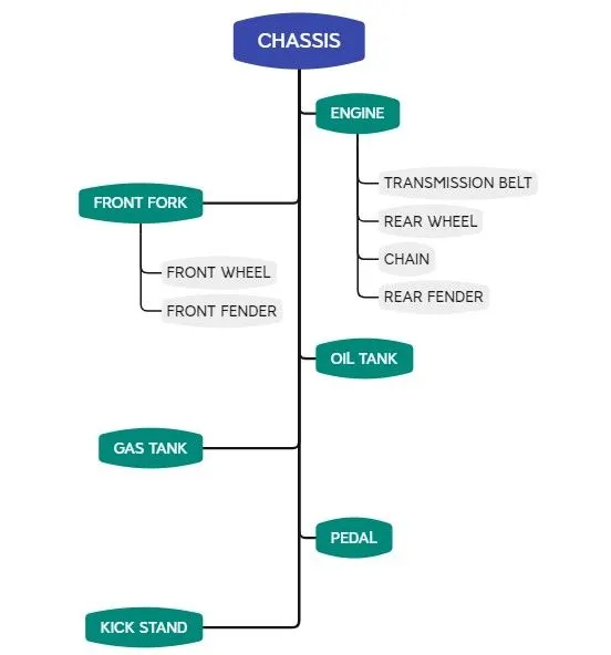
Description of Tool/Feature
The various modeling features used for modeling the American chopper are discussed below
- Extrude:
Extrusion is a method of defining three-dimensional geometry by translating a two-dimensional sketch normal to the sketch plane, for a predefined distance or up to a specified reference. Use the Extrude tool to create a solid or surface feature, and to add or remove material. First, we have to draw a closed 2d Sketch then make that into extruding the feature by defining depth value. The depth should be given from the reference Sketch or edge.
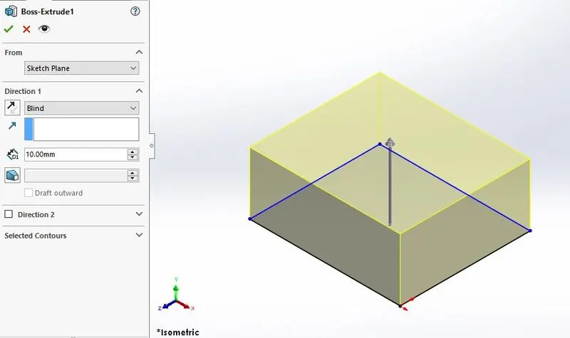
Fig.1. Extrude feature.
- Mirror:
Mirroring is another way that SolidWorks can create a “copy” of an existing object. Additionally, we must choose a plane to mirror parts. In most cases, you will have to create your own plane or sketch to have the mirror done the way what we need. The ability to mirror can be found in part and assembly files and allows you to mirror sketch entities, features, faces, bodies, and components. There are two mirror functions available while working with 2D sketches, mirror entities, and dynamic mirror. Both allow you to mirror parts of a sketch about a straight line.
Mirroring of part or 2d sketch can be done derived from the Original version, it projects the sketch on the opposite side of an existing one about the centerline. Dimensions can be added before or after the mirror depending on preference.
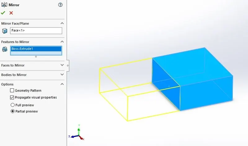
Fig.2. Mirror Feature.
- Revolve:
To create revolve in SolidWorks, you need a sketch from which revolve can be created as well as an axis for this sketch to be revolved around. The first thing to understand is the sketch profile should look like to create revolve. The revolving feature involves the spinning of a 2D profile around the axis of revolution and converts it into the 3D Profile. The axis can sketch, edge of the existing feature. The Revolve feature is defined by the angle of rotation.
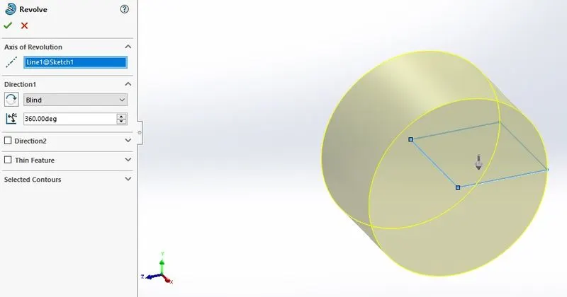
Fig.3. Revolve Feature.
- Sweep:
A Sweep is a tool that creates a solid, surface feature by moving a profile along a path. First, define the sweep profile then define the sweep path SolidWorks offers three different types of sweep profiles: sketch, circular and solid. To create a solid, use the Swept Boss tool to move a profile along a path. The profile can contain one or more closed contours. If the profile is circular, the new Circular Profile option only requires a path to be sketched.
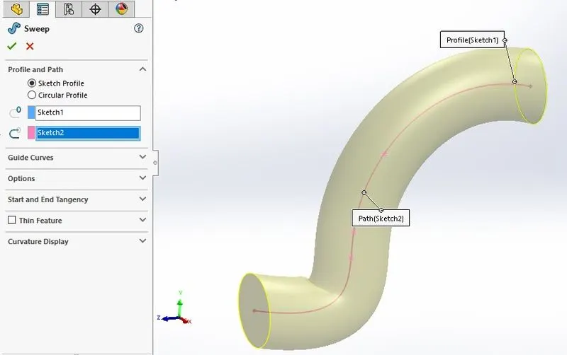
Fig.4. Sweep Feature
- Fillet:
The Fillet is a common feature which is rounding of an interior and exterior corner or face of a part design. It can be created by selected an edge of a part and define it by radius, type, and location.
The option for “Tangent propagation” is one of the most powerful and useful options included in the Fillet feature. With this option selected, you can choose to create a single fillet, and any tangent edges or tangent faces that this fillet encounters will automatically become filleted as well. This can be a huge time saver, as it often omits the need to select these additional edges or faces. when the toggle tangent propagation is ON, it observes that any tangent edge from the original edge encounters is automatically filleted with the same value as the original edge. Otherwise, it should be select the single edge for fillet.
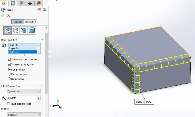
Fig.5. Fillet Feature.
- Chamfer:
The chamfer is a transitional edge between two faces of the part. It can be used to remove to a sharp edge and make into the sloped edge by defining with distance and angle of the chamfer. Here the tangent propagation helps to identify the tangent edges or tangent faces that this Chamfer encounters will automatically become chamfered as well. It can be created by selected an edge of a part and define it by distance, angle depend upon the selected Chamfer type.
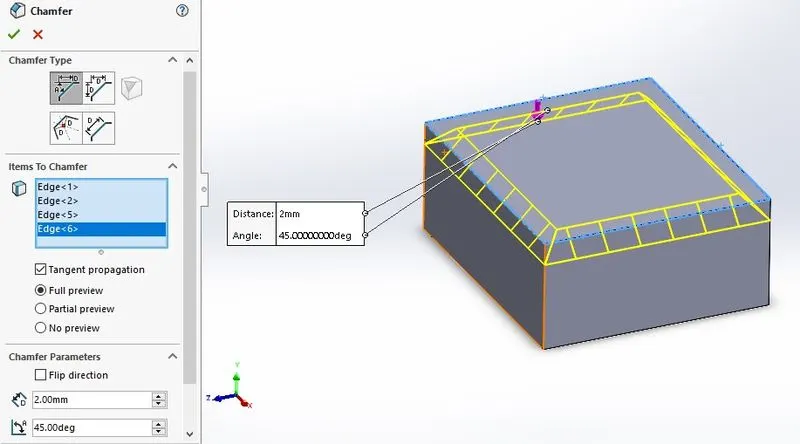
Fig.6. Chamfer feature.
- Shell:
The Shell command allows you to define a wall thickness and automatically hollow the part while allowing faces to be removed as needed. If no faces are specified to be removed during a Shell feature, the part will be hollow, but this can only be seen by creating a cross-section of the part. Access the Features tab of the Command Manager and activate the Shell command. The first input allows the wall thickness to be specified. The second selection allows specified faces to be removed from the model.
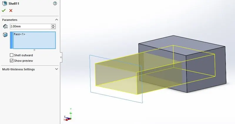
Fig.7. Shell Feature.
- Linear and Circular pattern:
Pattern commands are a designer’s best friend in terms of replication and improving overall efficiency. This offers a great amount of flexibility in terms of placing the features. Linear and Circular driven patterns are all common commands used by the everyday CAD user. The tool will be enabled by defining the number of instances and distance or angle.
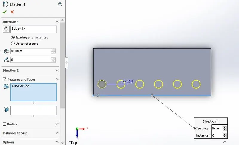
Fig.8. linear Pattern Feature
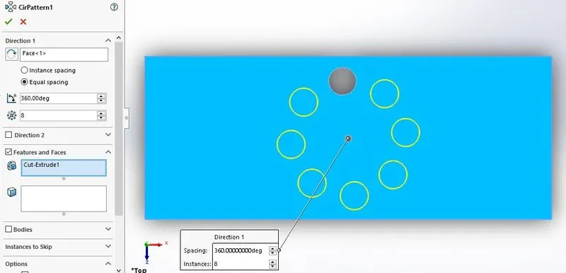
Fig.9. Circular pattern Feature
- Projected Curve:
Using the tool, to create a 3D curve with help of two 2D curves which are drawn on an intersecting plane. Align the sketch profile such that when they are projected normal to their sketch plane; the implied surfaces will intersect, creating the required result. It helps us in designing the complex surface model.
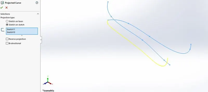
Fig.10. Projected curved
- Mates:
When we create a part in SolidWorks, the position of each body is defined in x, y, z space. When we create an assembly, we use Mates to define components relative to each other. The first part should be fixed in space, which saves us several Mates at the outset. The next should be defined relative to the first, and subsequent Mates defined relative to the already mated geometry. To restrict the movement, by keeping the number of degrees of freedom for movement in the assembly to a minimum. Some of the mates are used in this project are coincidence, tangent, parallel, perpendicular.
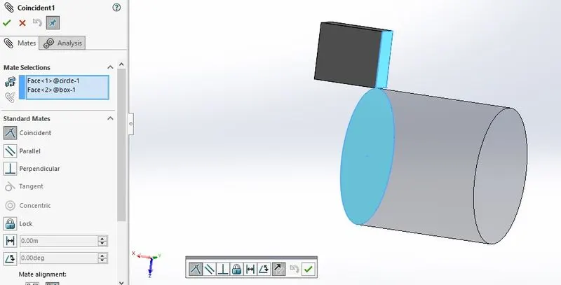
Fig.10. Mate in the Assembly part
Description of model
- Transmission Belt:
The transmission Belt is used to transmit the power from the engine to the transmission box. It was modeled by using basics tool such as Extrude and Fillet.
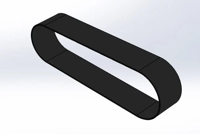
Fig.11. Transmission Belt.
- Kickstand:
A side stand-style kickstand is a single leg that simply flips out to one side, usually the left side, and the bike then leans against it. Side stands can be mounted to the Chassis and make contact with the ground. It was modeled by using a loft tool and the dome was applied to its end. The split tool was used to create a flat bottom end. The extrude cut and fillet were given to part.
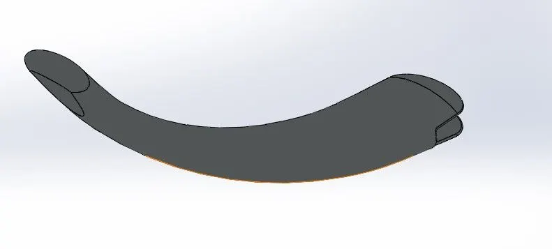
Fig.12. kick Stand
- Front and Rear Fender:
A fender is the part of a motorcycle or other vechicle body that frames a wheel well. Its primary purpose is to prevent sand, mud, rocks, liquids, and other roads sprays from being thrown into the air by the rotating tire. Fenders are typically rigid and can be damaged by contact with the road surface. it was modelled by using Revolve, Split and fillets.
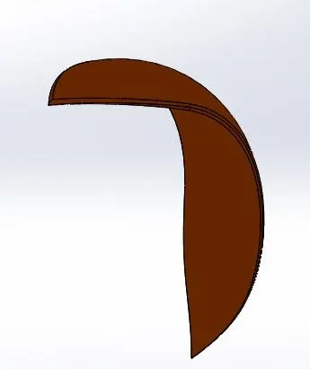
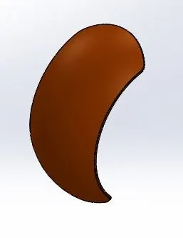
Fig.13. Front fender Fig.14. Rear Fender
- Chain:
A chain is a mechanical element that is used to transmit the power from the transmission box to the rear wheel. It is a combination of a link connect to form a Chain. Though it is a complicated model, it can be modeled with mirrors, Curves, and curve-driven patterns. The link was modeled as blocks and later imported into the curve-driven pattern was done multiple times to get the acquired part.
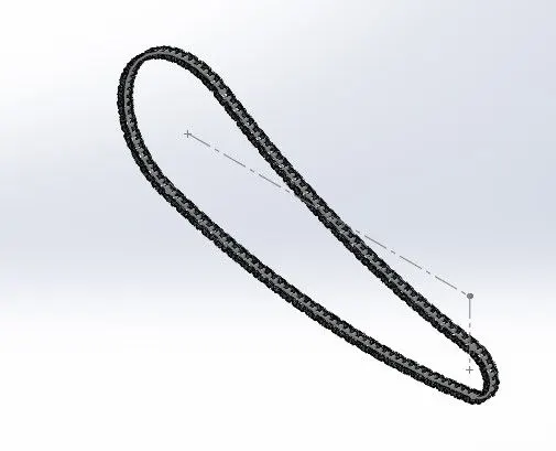
Fig.15. Chain
- Oil tank:
An oil tank is a safe Container for flammable fluids in which the fuel is stored and propelled and released into an engine. Fuel tanks range in size and complexity. The oil tank was modeled by the dynamic mirror entity and combine feature. The shell feature is used to make a hollow part.
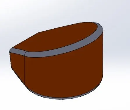
Fig.16. Oil tank
- Pedals:
The pedal is a strong rigid body and is used to rest the foot while driving a bike. It was modeled by the splines, fillets, dome, and liner pattern.
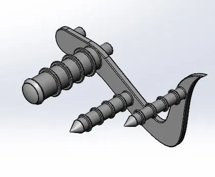
Fig.17. Pedal
- Front-wheel :
The front-wheel consists of Rim, Tyre, Disc Rotor and Calliper is attached to the front fork. It was modeled by using Revolve, Fillet, Extrude, splines, linear pattern. The spider spokes are modeled by arcs and offsets.
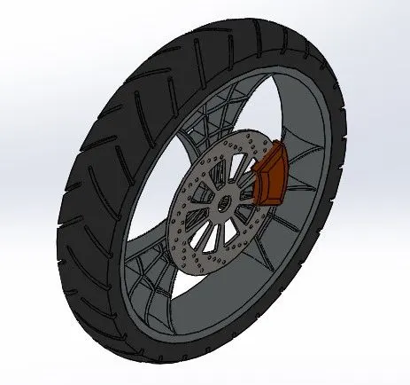
Fig.18. Front-wheel
- Rear-wheel:
The Rear receives the power from the engine and is used for accelerating the motorcycle forward. It was wider than the front wheel to improve the stability of the bike. The steps are followed are the same as the front wheel here. The Rear sprocket is added part.
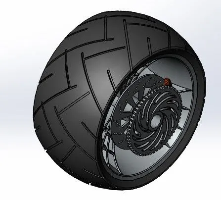
Fig.19. Rear Wheel
- Front fork:
A motorcycle fork connects a motorcycle's front wheel and axle to its frame, typically via a yoke, also known as a triple clamp, which consists of an upper yoke joined to a lower yoke via a steering stem, a shaft that runs through the steering head, creating the steering axis. Most forks incorporate the front suspension and front brake and allow the front wheel to rotate about the steering axis so that the bike may be steered. It was designed by Revolve, Mirror, extrude. The projected curves is used to make handle and brakes Cables.
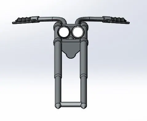
Fig.20. front fork.
- Chassis:
Chassis is the main support structure of the vehicle which is also known as ‘Frame’. It bears all the stresses on the vehicle in both static and dynamic conditions. Its modeling was initiated by using a sketch as a Reference for sketching. It also includes the splines, sweep, fillet, and split.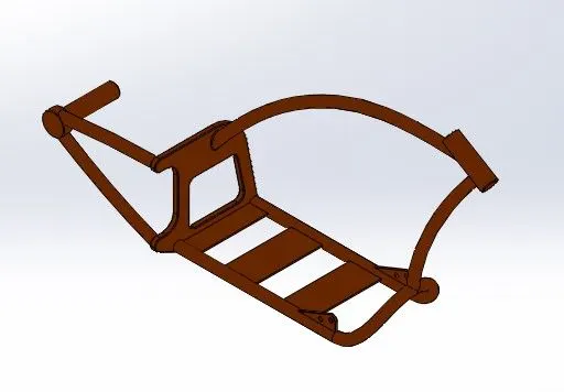
Fig.21.Chassis
- Engine:
The engine is the heart of the bike. It produces the power to drive the vehicle. A picture is imported for reference, the lower part of the engine contains a crankcase is modeled. Then transmission box is modeled. Then the upper part of the engine contains a cylinder with fins, air filter, and Engine sprocket is modeled. Finally, the exhaust and Spark plug is modeled with the help of Splines and projected curves.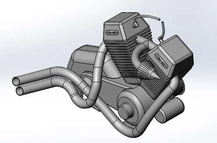
Fig.22.Engine.
- Gas tank:
The Gas tank shields the engine that prevents the heat from the engine. The opening for the fuel tank and seat are provided at top of the tank. It also involved using a reference Picture sketch. Tha half of the gas tank is modeled and the mirrored. The seat is modeled over the top and fillets were applied. At last, the shell tool is used to create a hollow portion.
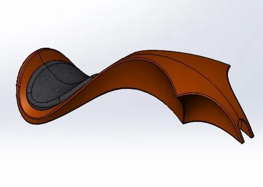
Fig.21.Gas tank.
Assembly of Chopper:
All the part models are imported into assmeby part and to make an assembly. Firstly the chassis part is to be placed. The mating feature is provided for perfect alignment or relocate the geometrical relationship with the chassis. The other parts are inserted and make a relationship with the chassis. Some of the parts needed to be modeled to make it a perfect assembly.
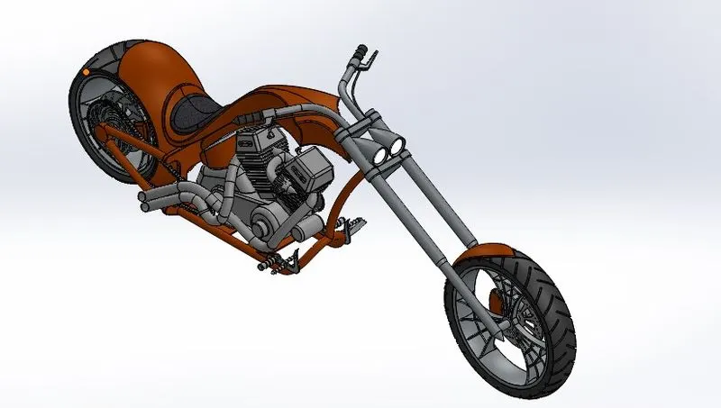
Fig.23.Assembly Part of Chopper
Rendering:
In this Rendering process, the chopper was set up in such a way that look natural and unique. Decals are added to the body parts. Viewpoints and camera direction are changed. With the help of Solidworks visualize, the scene and the appearance has made changes. The final rendering was done to make the chopper, realistic and digital.
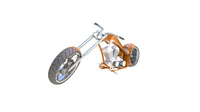
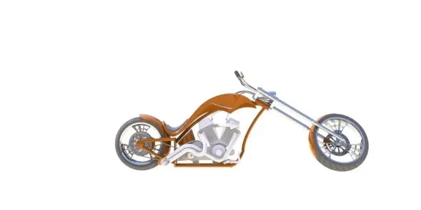
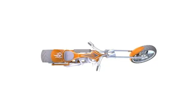
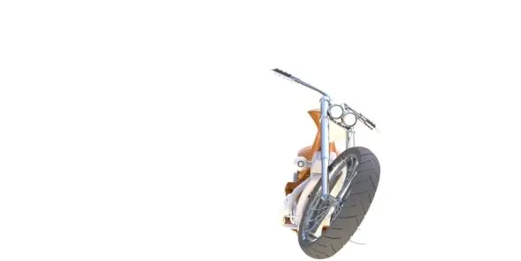
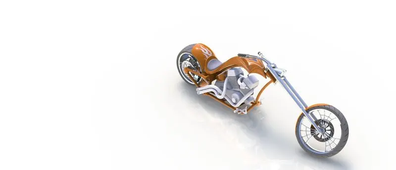
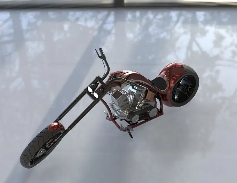
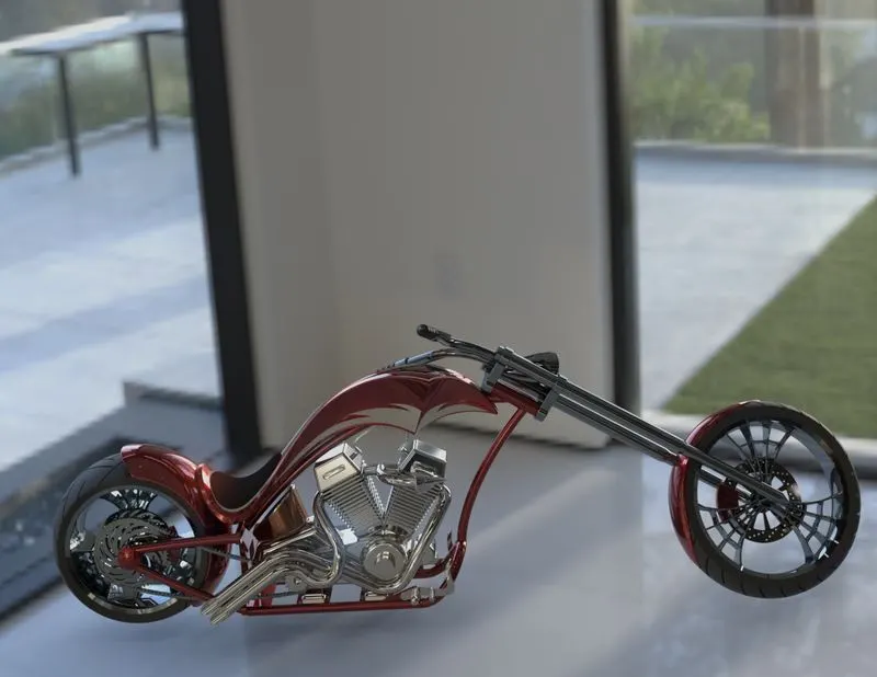
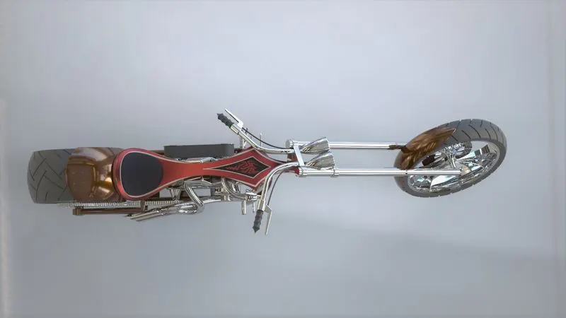
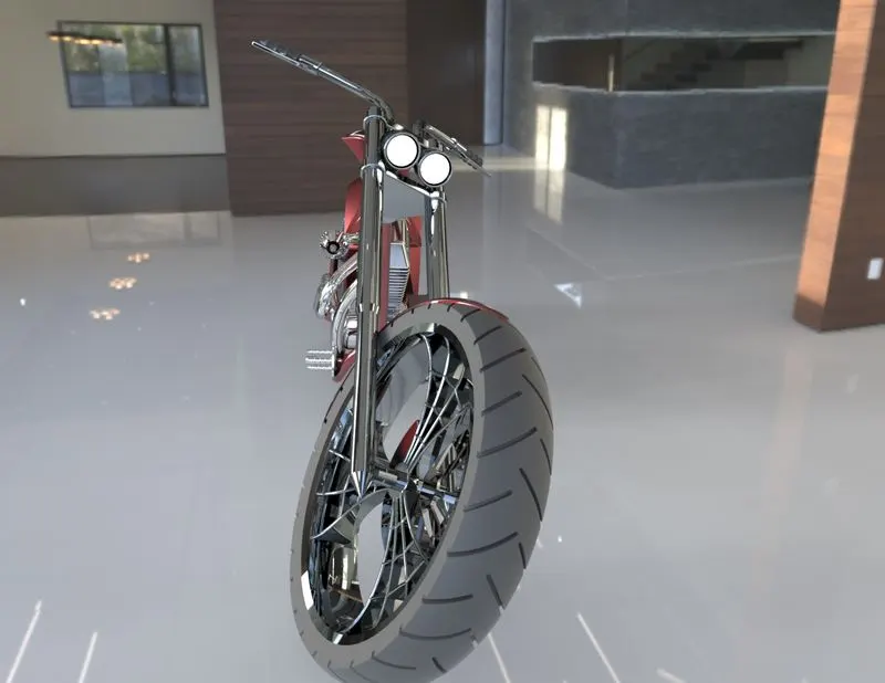
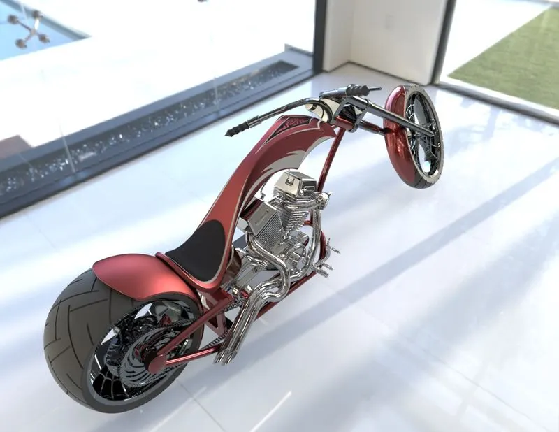
Fig.24.Rendered Images(Camera setup view, Front View, Top View, Side View, Isometric view)
Conclusion:
In the project, The modeling of the individual part of Chopper and assembled it by using the feature on SolidWorks. Decals were added to the respected body. The environment and scene were imported to make a chopper look Realistic and digital.