Advanced Sheet Metal Design Using NX Cad Challenge_7_ Metal bracket-II
Design of the Metal Bracket
Objective:
To design the Metal bracket using the Siemens NX.
Introduction:
Sheet metal is metal formed by an industrial process into thin, flat pieces. Sheet metal is one of the fundamental forms used in metalworking, and it can be cut and bent into a variety of shapes.
The sheet metal application provides an environment for the design of the sheet metal parts are used in machinery, automotive aerospace.
Design Methodology:
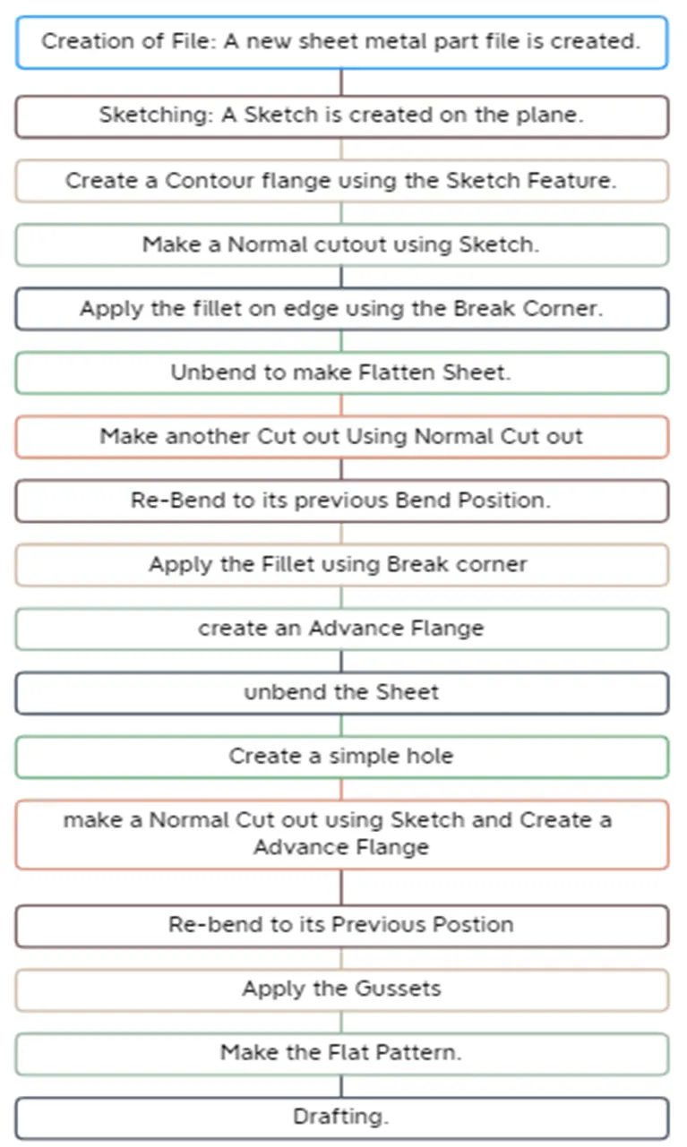
Description of tool:
- Sketch:
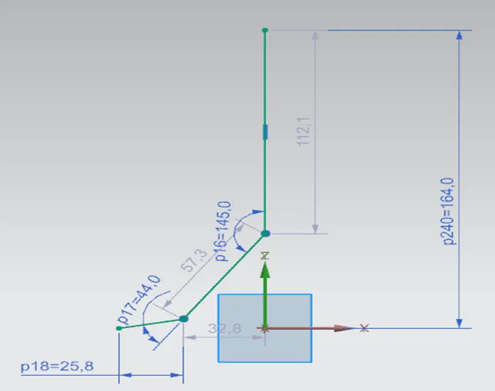
The Sketch feature is used to create a basis sketch for the on the required plane for the creating the contour Flange on it.
- Contour Flange:
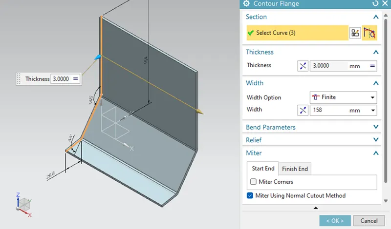
The feature is used to create a base feature by extruding along a vector. Here the contour flange created with thickness of 3mm and to a length of 158mm.
- Normal Cut out:
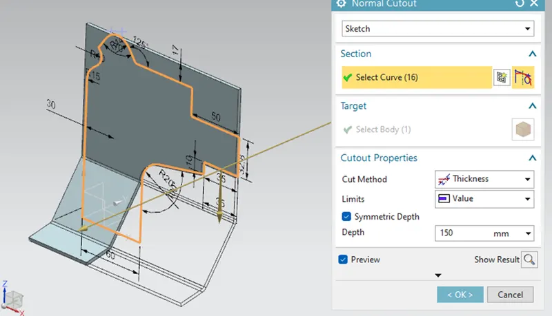
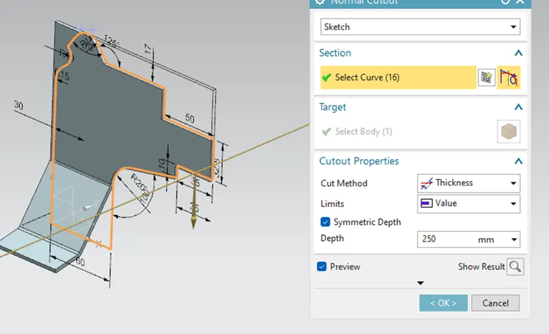
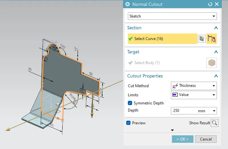
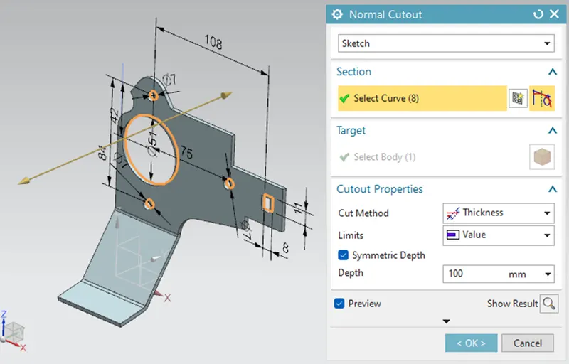
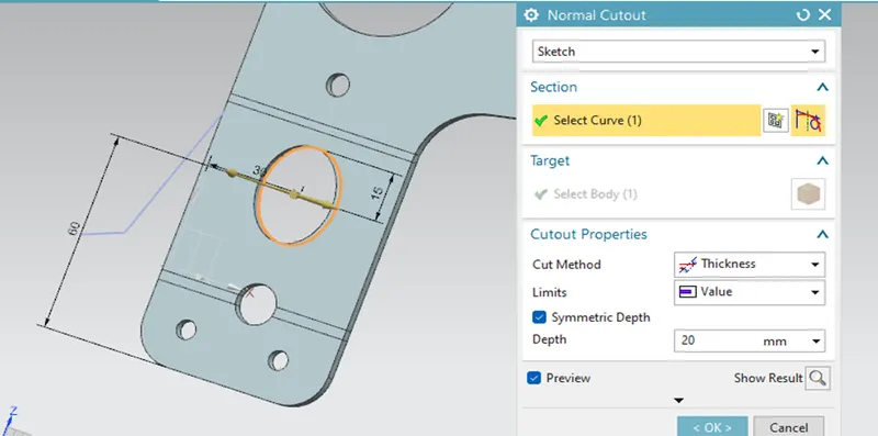
The normal cut out feature is used to cut the material along thickness of the sheet with the help of sketch on the model. Here in this model, normal cut out is carried in three steps to remove the material with the help of sketch.
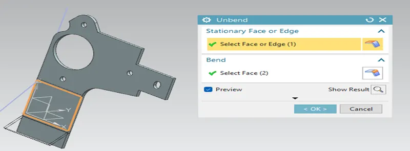
- Unbend:
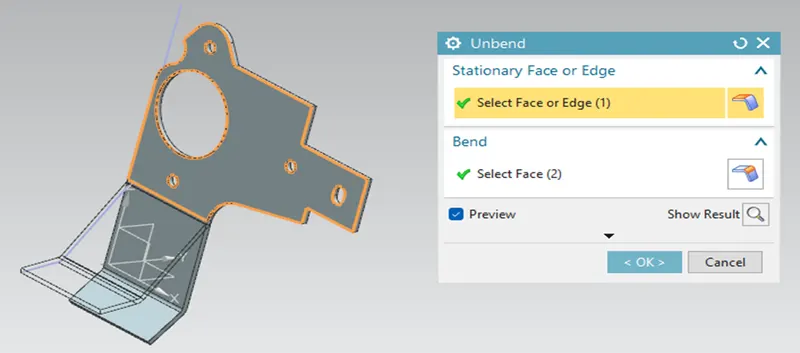
To make flatten the bend surface, this unbend feature is used. Here in this activity, to make flatten, the unbend is performed twice due to presence of two bends.
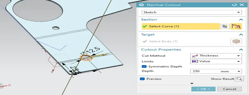
- Normal Cut out:
Here, again the Normal cut out Feature is used to create a hole at the portion of the bracket.
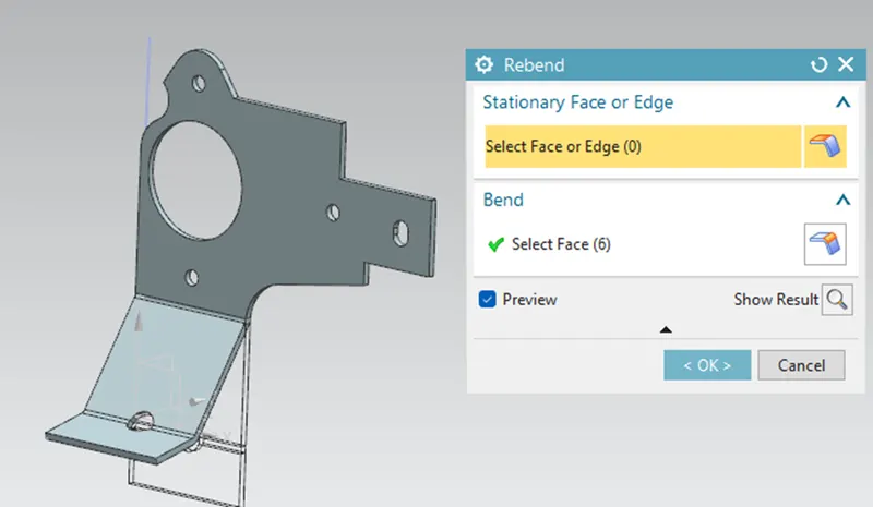
- Re-bend:
The Re-bend Feature is used to get the flatten one to its previous bend position. It is carried out by selecting them in reverse order of bend to get the design sheet metal product.
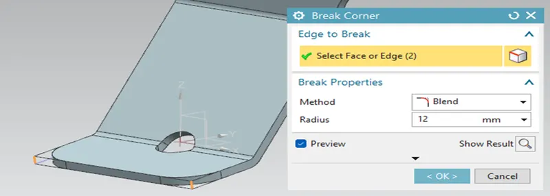
- Break Corners:
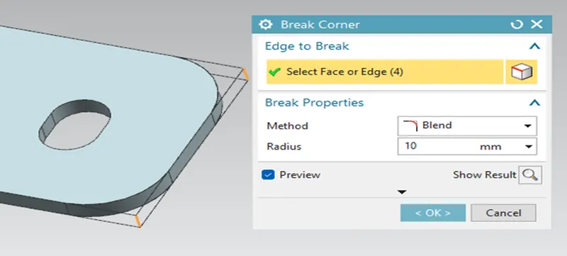
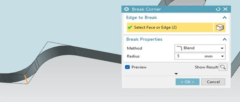
The Break Corner feature is used to make a Sharp edges to Round edges to decrease the stress Concentration over the area.
- Advance Flange:
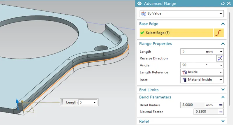
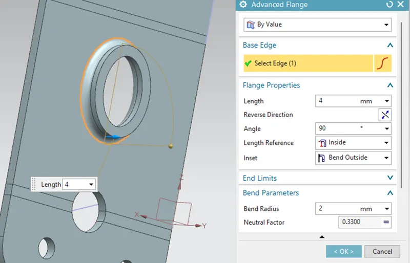
With this command, to add a flange along an edge using bend angle or a reference face. The edge and reference face can be curved. You can select the single edge or a chain of tangent edges. Here, the flange length of 5mm is given and angle is 90 degrees.
- Unbend:
Here again the Unbend Feature is used to make the flatten the sheet to design the hole at lower portion of bracket.
- Hole:
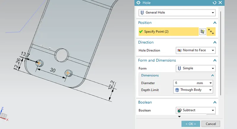
The Hole Feature is used to create the holes with design parameter. Here the diameter of the simple hole is 6mm is created.
- Normal Cut out and Advance Flange:
- Re-bend:
The Re-bend Feature is again used to make the flat sheet to its previous bend position along with any feature added after the unbend feature.
- Gussets:
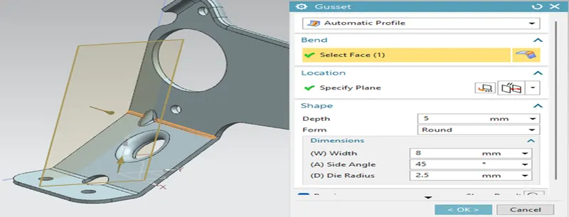
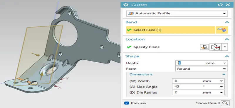
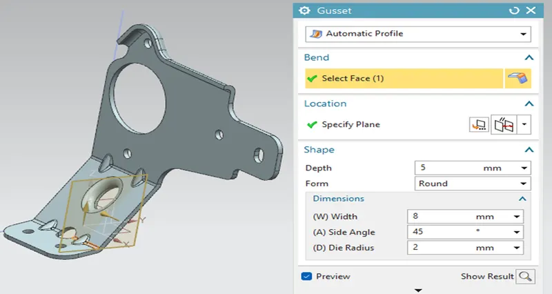
Gussets Feature is Stiffening Feature which help to add the strength between the two surfaces.
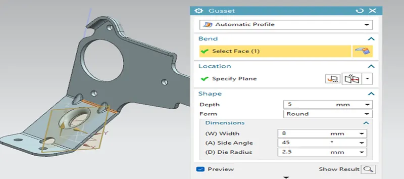
First we have designed the gussets at edge between two planes or surfaces before the un-bend and re-bend Feature. If the Stiffening Feature of gussets is created after the un-bend and Re-bend feature, then it will get hidden. To Show that the Stiffening feature, we need to replace the stiffening feature after the unbend and re-bend in Feature Tree of the model.
Here in this model, the width of gusset is 8mm and die radius is 2.5mm and side angle of 450 is designed at the upper edge. At the down bend surface, Die radius is 2mm and the side angle and the gusset is same as previous gusset.
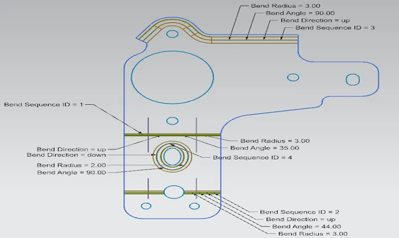
Flat Pattern:
Model Views:
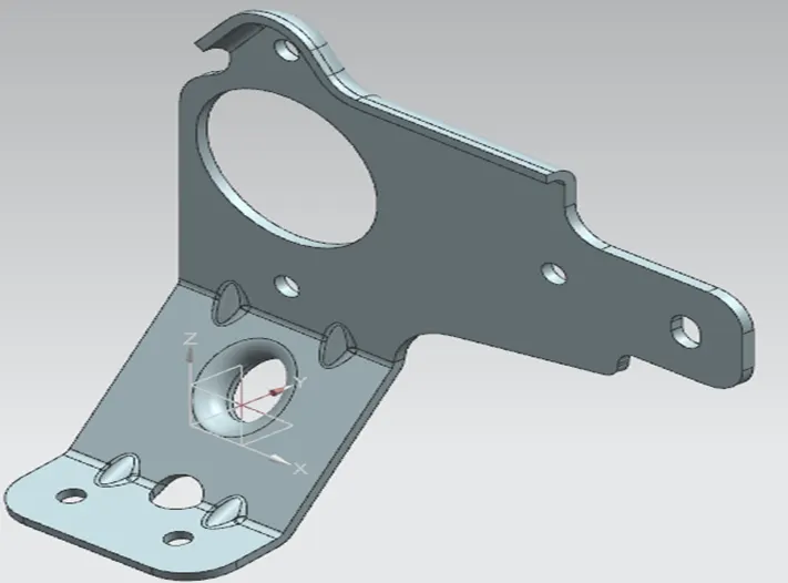
Isometric View:
Front View:
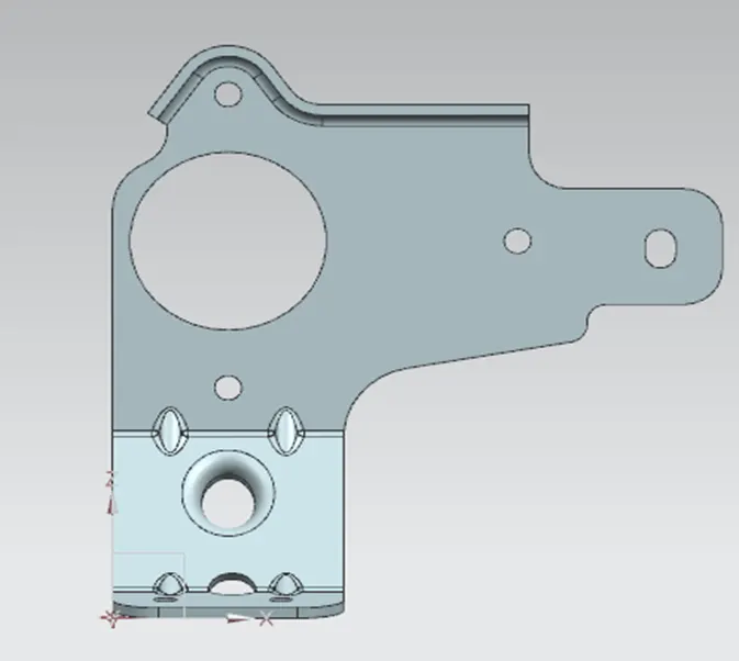
Top View:
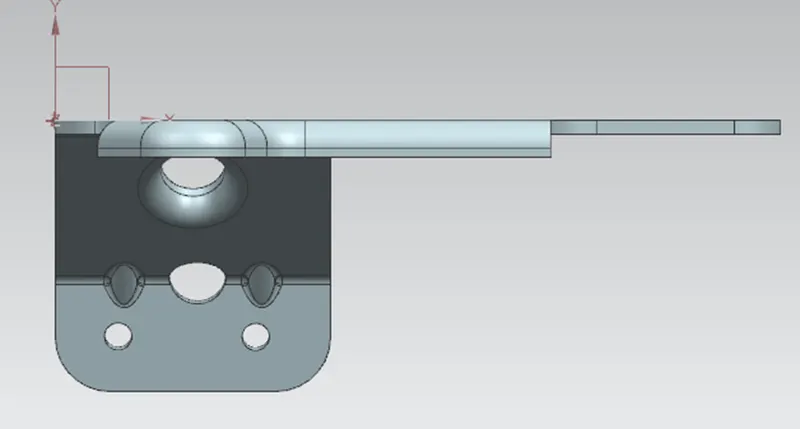
Side View:
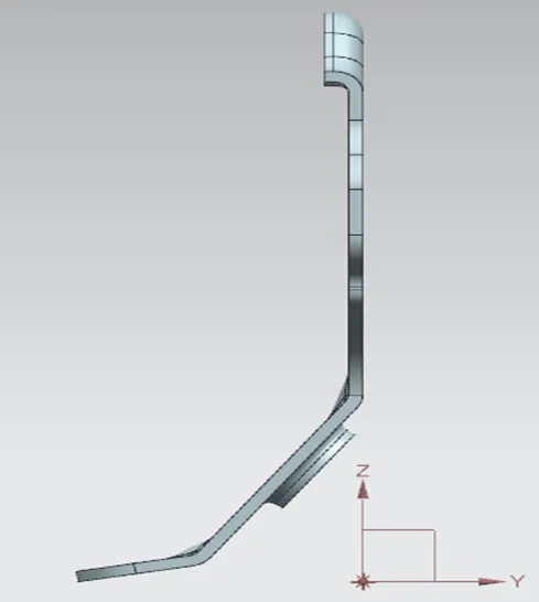
Drawing:
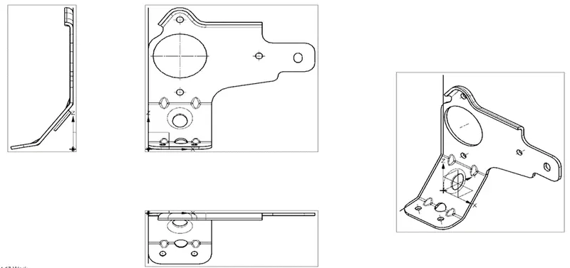
Conclusion:
The design of the metal bracket using Siemens NX and plotted the Flat pattern and the drawings.