Advanced Sheet Metal Design Using NX Cad Challenge_1_Casing Design
Design of Casing:
Objective:
To design the sheet metal component of Casing Using NX Cad tool.
Introduction:
Sheet metal is metal formed by an industrial process into thin, flat pieces. Sheet metal is one of the fundamental forms used in metalworking, and it can be cut and bent into a variety of shapes.
The common engineering metals are also used in the form of sheets. Some of them are carbon steel, stainless steel, copper and aluminum, nickel and titanium.
The thickness of sheet metal starts from 0.5 mm and goes up to 6 mm and anything above that is a metal plate. The thin sheet metal is easy to form, while still providing great strength
Sheet metal is one of the most versatile and widely used construction materials, with applications in just about every industry imaginable from mining, construction, farming, catering, hospitality, shipping, manufacturing, aviation, medical and transport.
Design Approach:
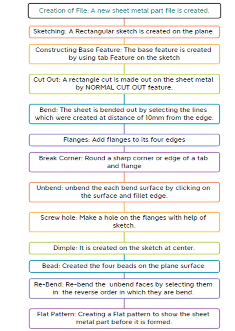
Description of Feature:
- Sketch:
This feature is used to create a basic sketch for the design on the desired plane and creates a tab on it.
- Mirror:
It replicates the part along the line on other side and helps to reduce the time.
- Tab:
The tab Feature is used to create a base feature by extruding along a vector by a thickness value, or by adding material to existing faces and bend region of a sheet metal part.
- Normal cut out:
It cuts the material by projecting the sketch onto the model.
- Bend:
It modifies the model by bending the material on one side of the sketch line.
- Flange:
The Flange Command is used to create a flange at an angle to a planar face and bend between two. A flange consists of bend region and Web.
- Break Corners:
The break corner Feature is used to make edges round at the sharp corners of a flange or a tab.
- Unbend:
Unbend is used to make flatten the Bend material.
- Hole:
It is used to create a holes to the requirement for the further assembly of the part.
- Dimple:
Use this command to create a raised dimple feature or lifts an area in a sheet metal part. The dimple can be placed on any flat face including flanges and will extend in the direction of the face. It is designed to reduce weight in sheet metal fabrications, while adding strength and rigidity.
- Beads:
To create a beads which are elongated recesses which are stamped into the sheet metal parts to increase the stiffness.
- Re-bend:
The Re-bend is used to bend the unbend faces. Re-bend the faces by selecting them in reverse order of bend to attain the actual sheet metal product.
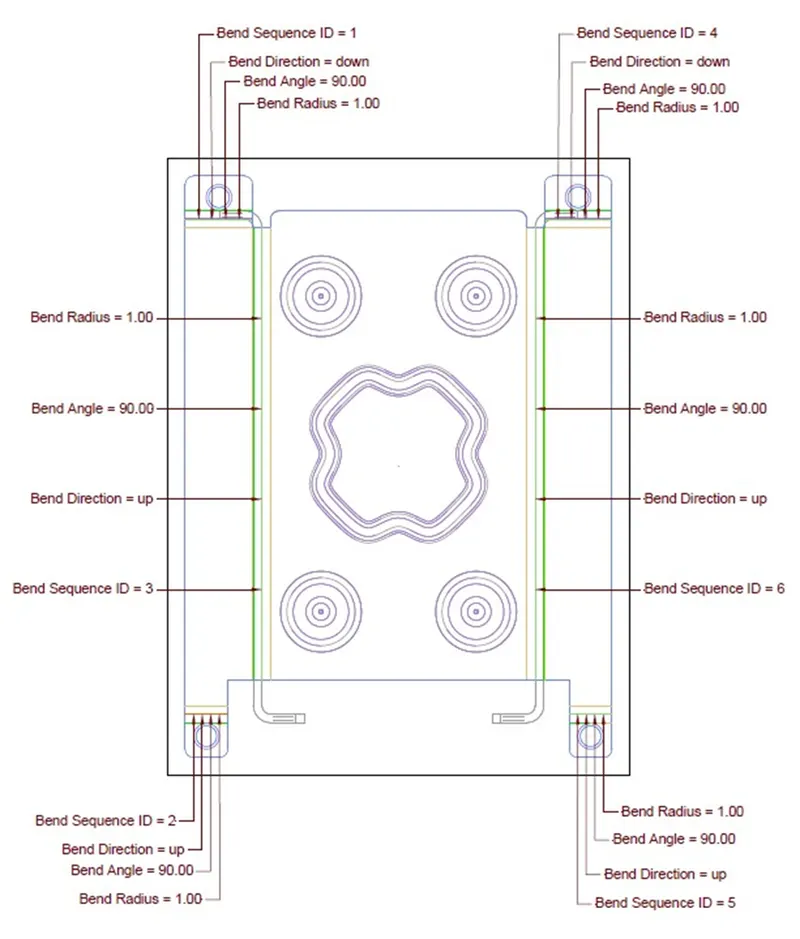
- Flat Pattern:
The Flat pattern Feature is used to create the shape of the sheet metal part before it is formed, to create drawings for manufacturing. Flat patterns show bend lines, bend zones, punch locations, and the shape of the entire part with all bends flattened and bend factors considered.
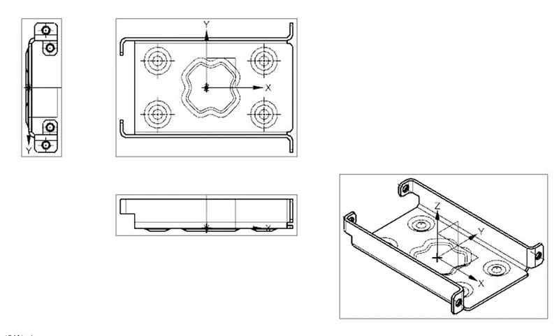
Casing Views:
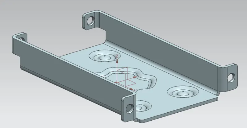
Isometric View:
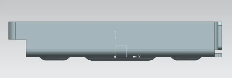
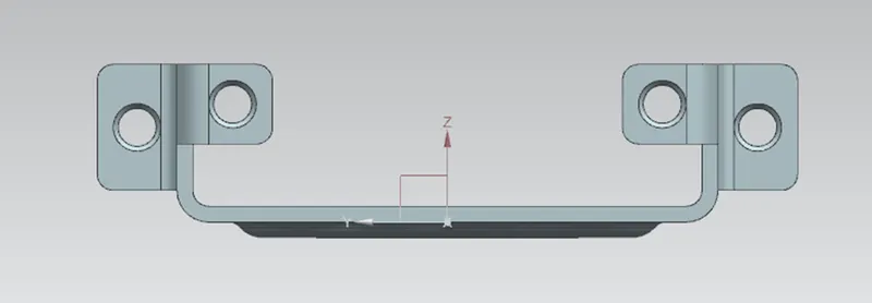
Front View:
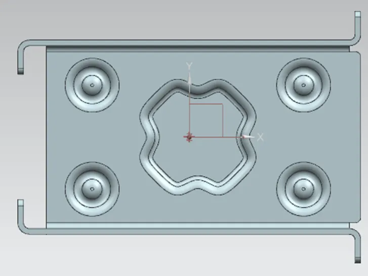
Top View:
Side view:
Flat Pattern:
Drawing Sketches:
conclusion:
The Designing of Sheet metal casing is done using NX cad.