Advanced Sheet Metal Design Using NX Cad Challenge_6_Bracket
Design of the Bracket
Objective:
To design the Sheet Metal component of the Bracket using Siemens NX and to create the flatten pattern.
Introduction
Sheet metal is a metal that is shaped into thin, flat pieces by hot and cold rolling industrial process. Sheet metal is one of the basic forms of metalworking and can be cut and bent into various shapes.
Sheet metal is made by running hot slabs of metal through a series of roughing rolling stands that makes them thinner and longer. To make them even thinner, these sheets go through finishing rolling stands and are then cooled and rolled into coils.
The sheets are made from different kinds of metals such as aluminum, brass, copper, steel, tin, nickel and titanium. The sheet metal thickness depends on the material needed for a project. Thicknesses can vary from 0.5mm -6.00 mm significantly; extremely thin sheets are considered foil or leaf, and pieces thicker than 6 mm (0.25 in) are considered plate steel or structural steel.
Sheet metal is one of the versatile materials in the manufacturing and construction industry with applications in every industry from mining, construction, farming, catering, hospitality, shipping, manufacturing, aviation, medical and transport.
Design Methodology:
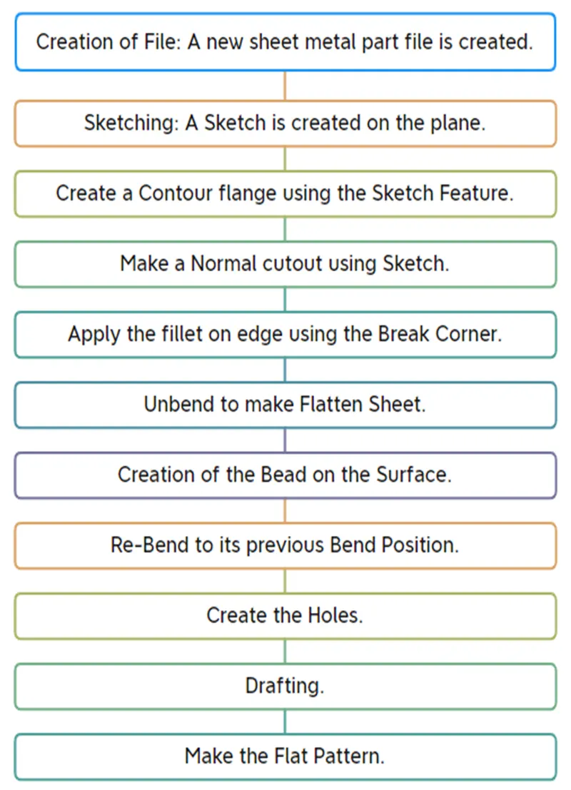
Description of Tools / Feature:
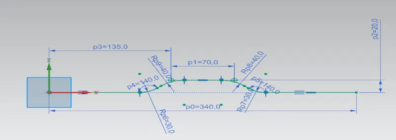
- Sketching:
The feature is used to create the basic sketch for design on the desired plane and generate the Contour Flange.
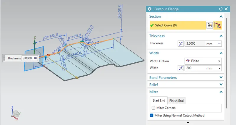
- Contour Flange:
The Contour Flange Creates the Base feature by extruding a sketch along a vector. Here, the contour flange with the thickness of the sheet metal and extruded to a length of 200mm is generated.
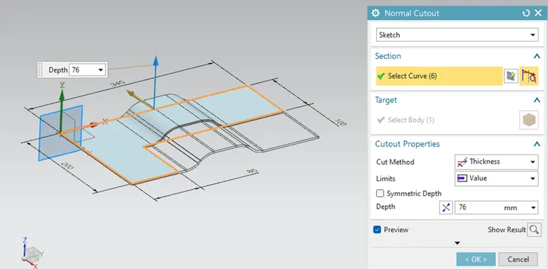
- Normal Cut:
The normal cut out feature is used to cut the material with help of sketch on the model and then removing the material perpendicular to the faces.
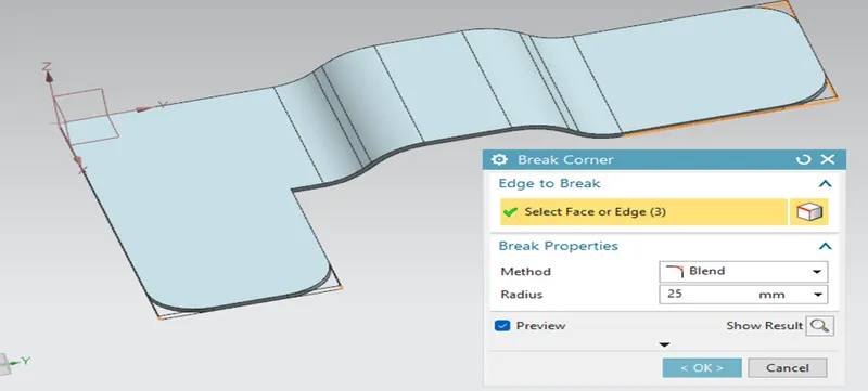
- Break Corner:
The feature is used to smoothen or chamfer the sharp edges of the sheet metal part. This will help to prevent the stress concentration and fracture breaking. Here I provided the 10mm blend.
- Unbend:
The un-bend feature is used to flatten the bend surface. For the marking and sketching on flat sheet metal before the actual operation. This Un-bend feature allow to do that activity in Siemens NX Cad.
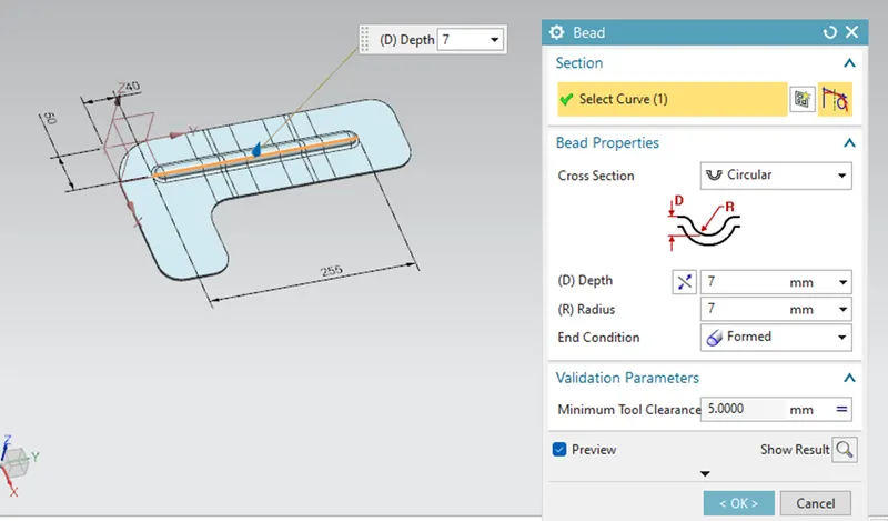
- Bead:
To create a beads which are elongated recesses which are stamped into the sheet metal parts to increase the stiffness. Here the sample one is designed and remaining things can be designed using the mirror feature option.
- Re-bend:
The Re- bend feature is used to regains to its previous bend position along with any feature added after the unbend feature. Re-bend the faces by selecting them in reverse order of bend to attain the actual sheet metal product.
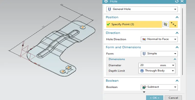
- Holes:
The Hole feature is used to generate the holes with definite parameter. It adds a hole to one or more in a solid body part or assembly with option for counter-bored, counter-sunk, and threaded. Here, in this design I had made a simple hole with a diameter of 10mm.
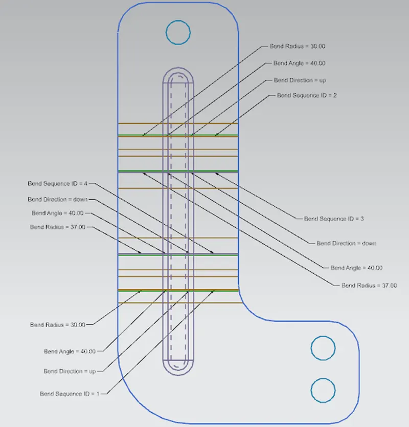
- Flat Pattern:
The Flat pattern Feature allows us to convert the 3D sheet metal into 2D in Siemens NX Software. The flat pattern is used to convey the information of the sheet metal operations and avoid collisions and interference.
Model Views:
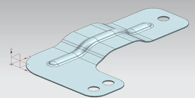
Isometric View:
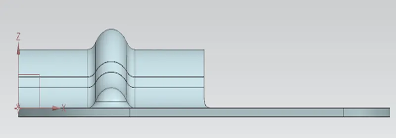
Front view:
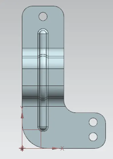
Top View:
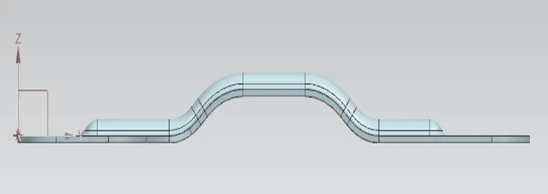
Side View:
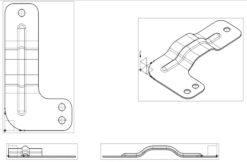
Drawings:
Conclusion:
The design of the Bracket using Siemens NX is completed and plotted the flat pattern and drawings.