Roof challenge
Automobile Roof Design
Objective:
For the given Roof Styling, Develop the essential flanges and reinforcements by providing the appropriate dimensions, find out the Section Inertia at the O-Y section and perform the draft analysis. To conduct the Curvature Study on the roof and perform the calculation to determine the position of the Bow roofs.
About the Car Roof:
An automobile roof or car top is the portion of an automobile that sits above the passenger compartment, protecting the vehicle occupants from sun, wind, rain, and other external elements.
Joining method:
For the roof, it will have a two joining method such as Mastic sealants are provided between the bow roof and the outer roof and, Spot Welding at the ditch area.
Reinforcements:
Sometimes the roof is flat, it becomes weak and cannot able to withstand the snow load as compared with the roof with curvature. With a focus on that, we have increased the strength of the roof by providing reinforcement. The different types of reinforcement that car roof has:
- Front Roof Rail
- Bow Roofs
- Center Roof Rail
- Rear Roof Rail
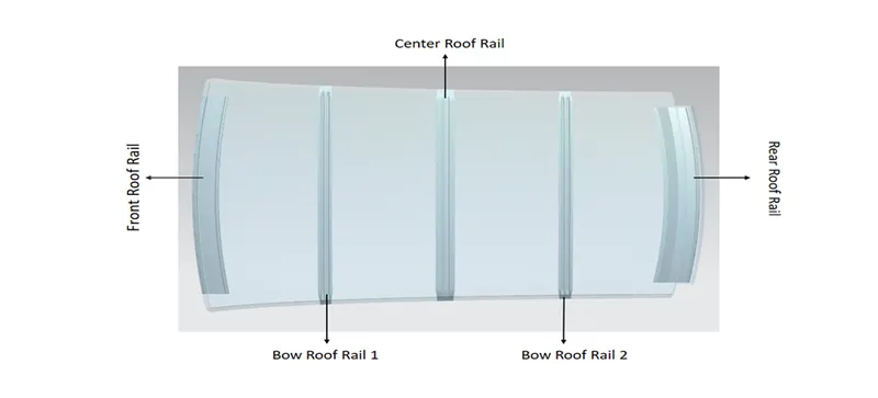
Front Roof Rail:
The Front roof rail is located at the front of the roof where it joins the windshield glass, body outer side. It was designed based on the given master section. The visibility criteria and headroom clearance of the occupants are taken into consideration from the bottom flange. One end of the roof rail is joined with a spot weld while the other end is joined with mastic sealant to increase the strength.
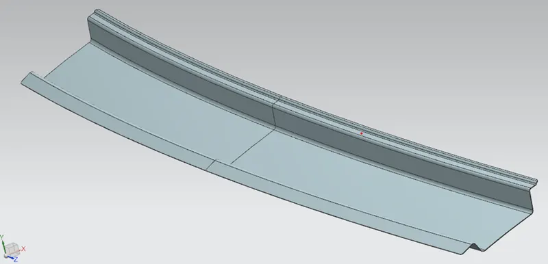
Rear Roof Rail:
The rear roof rail is located at the rear end of the roof. It joins the back door and the body's side outer. The inputs from the backdoor are taken into consideration for designing the rear roof rail.
The joining, at the one end of the rear roof rail, is done with mastic sealants and at the other end with spot welding.
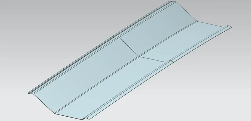
Center Roof:
The Center roof is located at the center of the roof. Here the reinforcement is added since it needs to provide more strength to the roof. The reinforcement joins with the roof with the help of mastic sealants and the ends are joined at the ditch area by using a spot weld.
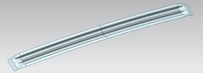
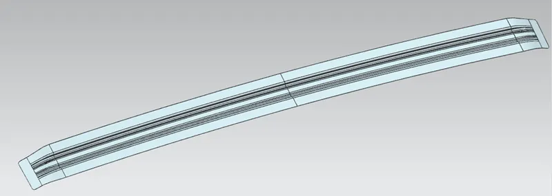
Bow Roofs:
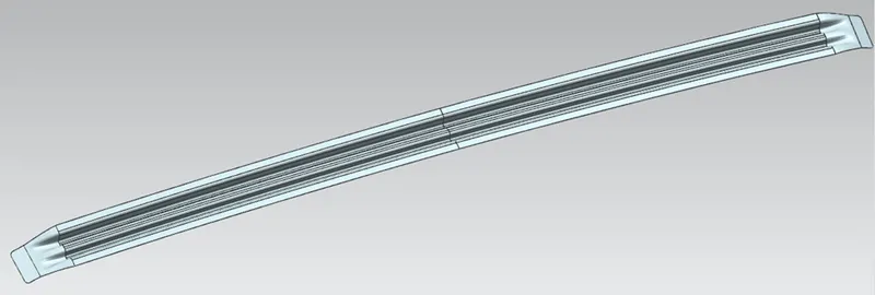
Bow roof is an additional member to increase the strength so that it can satisfy the design condition in case of a large roof length. Both end are joined using mastic sealants to increase strength.
Design consideration:
- Visibility Criteria
- Head Clearance
- Heat distortion and snow load criteria
- Draft analysis
Heat distortion Criteria:
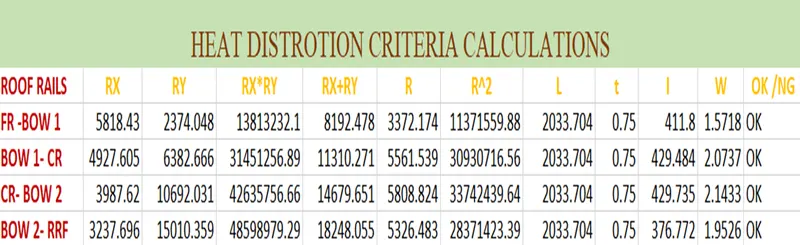
The study is carried out to check the ability of the roof to withstand high temperature concerning the position of the Reinforcements which contribute to increasing the strength. So to avoid roof damage or bending, we have to make calculations and decide the position of the bow roof-rail on the roof
Formulae:
W= [1.73*10*(-3) *L] + [1.85*10^ (-8)*R^2/t] + [1.10*10^ (-3)*I] - 2.68
Judgement Condition: OK<2.7mm
Where,
L = Roof length in X- direction (mm)
R = Roof Curvature = 2(Rx*Ry) / (Rx + Ry)
Rx = X Curvature
Ry = Y curvature
t = Roof Plate Thickness (mm)
I = Bow Roof Span (mm)
* The heat distortion is carried at distance of 300mm from center.
Snow Load Criteria:
This study is carried out to predict the roof behavior when it is covered with snow. Due to the snow weight, the dent will happen. To avoid the dent, the roof should be designed in a way that it should regain its original position when the snow load is removed. For that, we made the calculation and determine the position and curvature of the roof.
Formulae:
Qr = [Iy * t^2] / [α * S *[ (Rx + Ry) / 2]^2*10^-8 ]
Judgement Condition: Qr ≥ 3.1
250 ≤ s ≤ 380
Where,
α = My * Lx^2 * 10^-12
My = y (Ly – y)
t = Roof Plate Thickness (mm)
Ly = Distance between the front and rear roof rails on the vehicle along with 0Y (mm)
Length of roof panel with the center point between Roof rail Front/Rear as the front and rear reference point.
Lx = Distance between the Left and Right end of the roof on the roof Bow (mm).
Y = Distance from the front roof Rail to Bow roof (mm).
s = Distance for which roof bow bears divide load (mm).
= [L1/2 +L2/2 ].
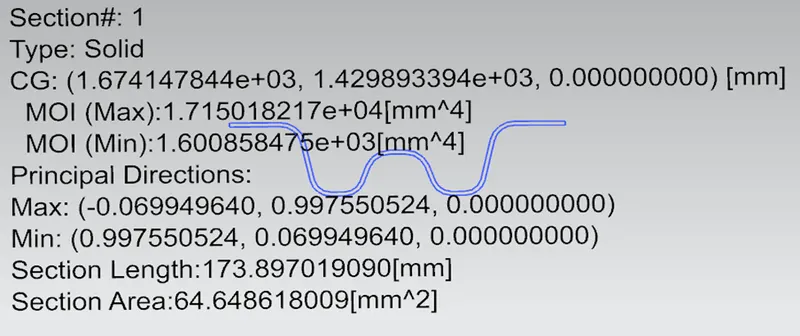
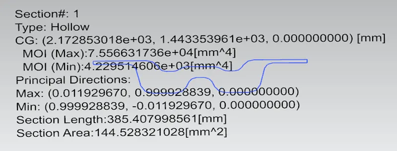
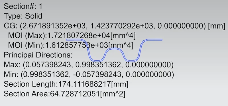
Iy = Geometrical Moment of inertia of roof bow (y cross-section) (mm^4)
Rx = Lateral Direction Curvature radius of the roof panel Y cross-Section on Roof Bow (mm)
Ry = Longitudinal Direction Curvature radius of the roof panel x cross-Section on Roof Bow (mm).
*Here the snow load criteria is carried out at 0-Y section or at the centre of the roof.
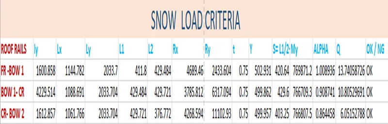
Here it satisfies the given judgment condition. Hence the position of the bow roof was determined.
If the condition doesn’t satisfy, then we make to suggestion to the styling team to modify the curvature radius. If the styling team doesn’t agree with that suggestion and then we have to design an emboss on the roof to increase the strength.
Section Modulus:
- Bow Roof Rail 1
- Center Roof Rail
- Bow Roof Rail 2
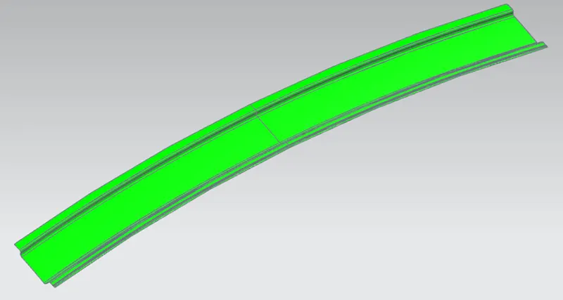
Draft analysis:
- Front Roof Rail
- Rear Roof Rail
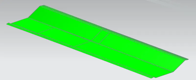
Bow Roof Rail 1:
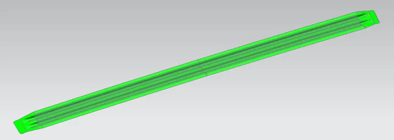
Bow Roof Rail 2:
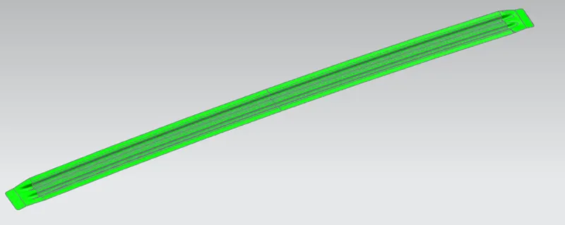
Center Roof Rail:
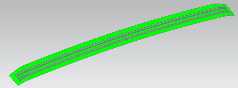
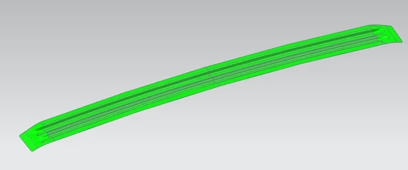
Roof Outer
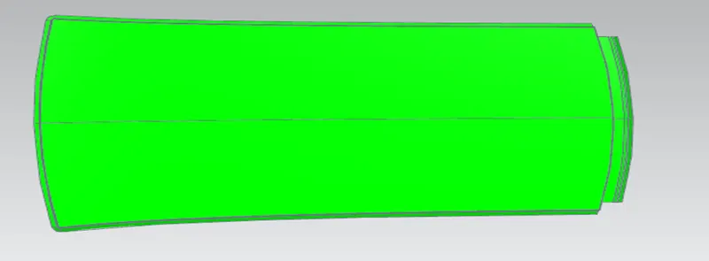
Here the part of the roof shows in green color and it indicates that it is provided with 3 degrees positive draft and it can be manufactured.
Conclusion:
We have developed the essential flanges and reinforcements by providing the appropriate dimensions with help of the given master section, found out the Section Inertia and performed the draft analysis. Conducted the Curvature Study on the roof and performed the calculation to determine the position of the Bow roofs.