Week 8 - Challenge 4 - Coin Holder Design
Design and Draft Analysis of Coin Holder
Aim:
To create the coin holder plastic component through the given Class-A surface and the tooling axis should be created meeting the requirements of the draft angle and at the end perform draft analysis.
Objective:
- To maintain the proper tree structure.
- Geometrical sets should have a proper name based on the sketches present it.
- All sketches should be created under the Geometrical set.
- Use the close surface feature to make a solid body from the Surface.
- Publish Tooling Axis, Class A, B, and C Surfaces.
Tooling Axis:
- Extract the base surface and create a point.
- Create a line along the Z direction and it will act as the main tooling axis. Since all surfaces in class A are in 90o, the tooling axis is directly created on the extracted part.
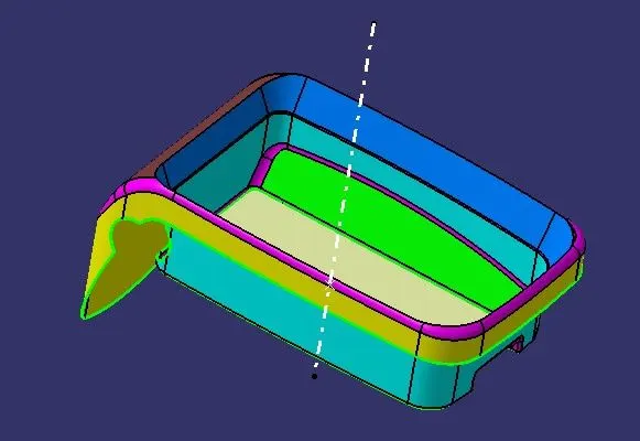
Creation of Class B Surface:
- Extract the sidewalls from the class A Surface and to un-trim it and finally extrapolate the surface to intersect with other surfaces and offset with a distance of 2.5 mm.
- Trim the required surface and apply the fillet values.
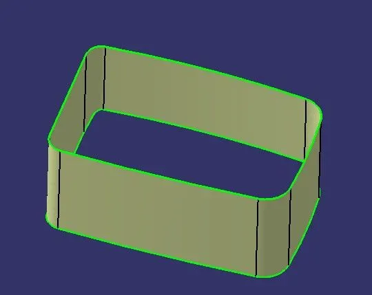
- Extract the base surface and un-trim it and extrapolate along with the point propagation and offset it.
- Trim to get the final surface.
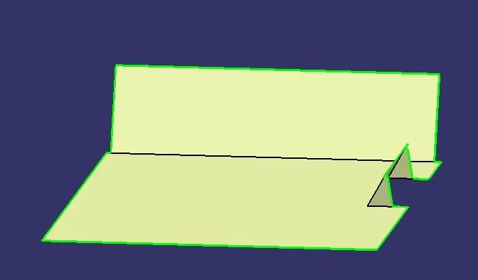
- After that, trim both surfaces to get the center box shape as below.
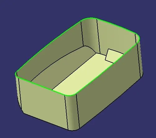
- Now Extract the top surface, un-trim it, and extrapolate it on both sides to intersect with side walls.
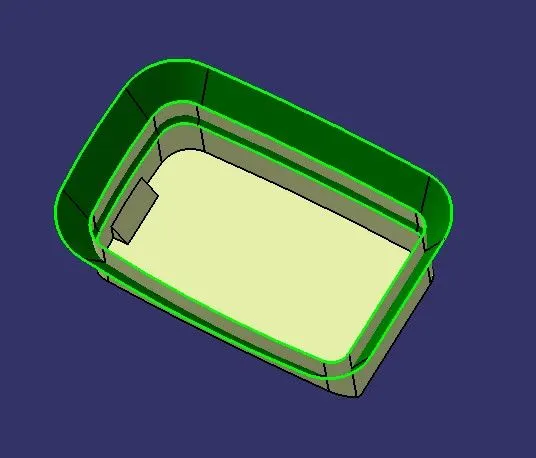
- Trim the surfaces to get the required output.
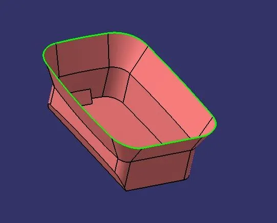
- Extract the outer flange surface, extrapolate it to intersect with other surface and trim it and apply fillets on the edges. Then the finally B-Surface is obtained.
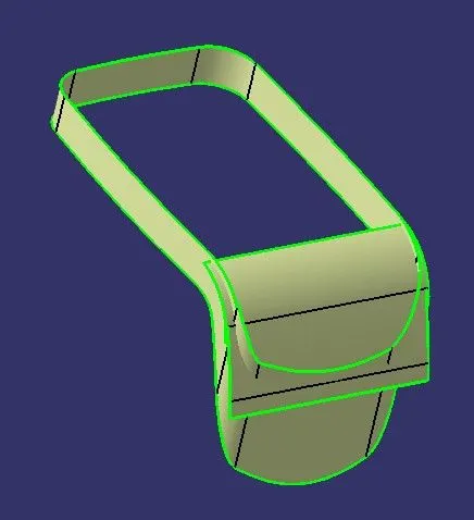
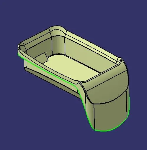
Creation of Class C surface:
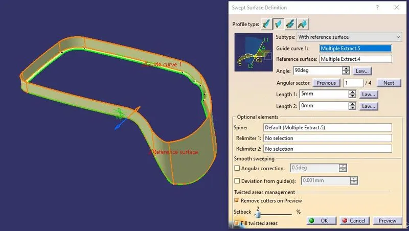
- Extract the outer flange and make a boundary line on the outer side to create C surface.
- Apply sweep option with reference surface (outer flange) and at an angle of 90O. Click on the inside arrow to form a Class C Surface.
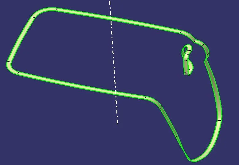
- Trim the class C surface with the Class B surface and join it with the Class A surface.
- Extract the Hole part in the coin holder and sweep it with reference and trim it to get the Final surface of the coin holder.
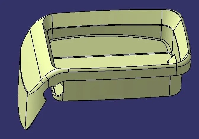
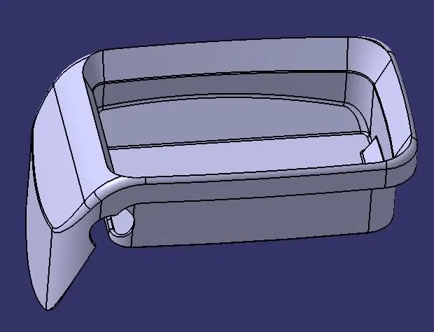
- Use the close surface feature by switching into the part workbench to create a part body.
Draft Analysis:
Before going to perform the draft analysis, we need to change the view customized mode into material mode and then perform the analysis.
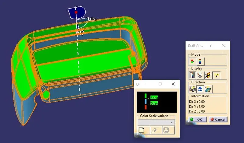
- Go to insert menu < Analysis < Feature draft analysis.
- Click on the compass and align it with the main tooling axis and click on the surface to get the color code on the surface.
- In the color Scale, give the draft value as 3 degrees.
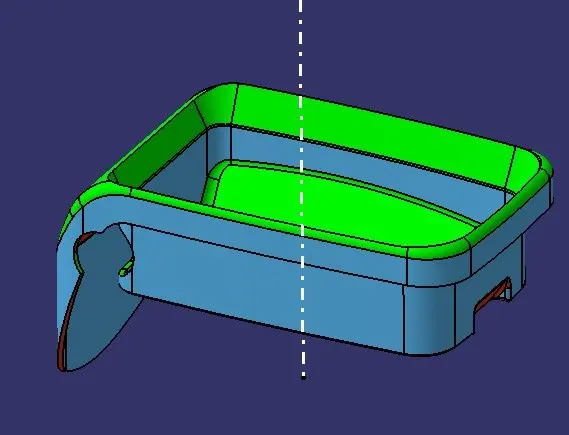
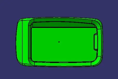
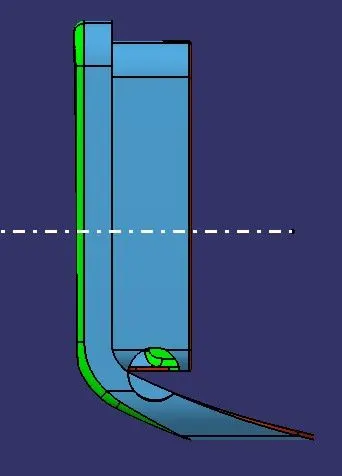
- The green color on the surface indicates that it has a positive draft angle which is above 3 degrees and easily removes from the mold without any defect on the surface and the Red color indicates the negative draft.
- The blue color indicates the surface has zero degrees which means that it is 90 degrees.
Tree Diagram:
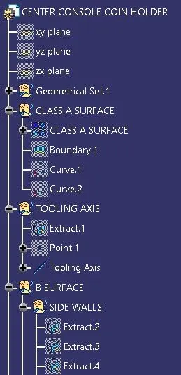
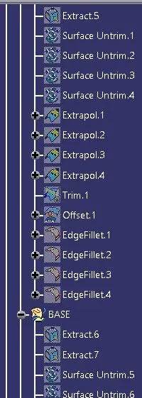
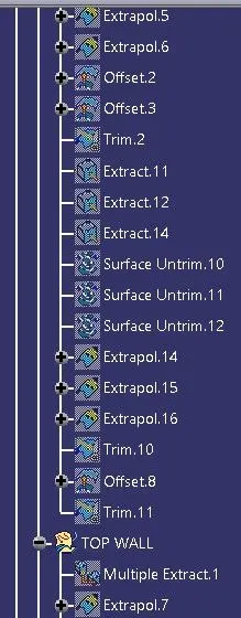
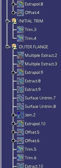
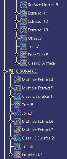
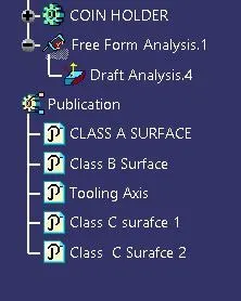
Conclusion:
The Tooling axis is created to meet the draft angle requirement and the class B and C surface is created. Finally, the Draft Analysis is performed and the maintained the proper tree Structure.