Week 8 - Challenge 1 - Draft Analysis on a Fan Cover
Draft Analysis of Fan cover
Aim:
To create the tooling axis for the given Fan Cover model to meet the requirement of draft angle and to perform the Draft analysis on the model to check if the part has provided the draft to every area of the component and it is eligible for production.
Objectives:
- To ensure the proper tree structure is followed.
- Geometric sets should have a proper name based on the sketches present inside of it.
- All the sketches should be created under the Geometrical set.
- Publications: Use the publication option and publish the Tooling axis and Class A surface.
Draft:
The Draft is defined as the amount of tapper is given to the molded or cast parts perpendicular to the parting line or concerning the tooling axis to make them easier to remove. It can be measured in degree. The tooling axis is the direction in which the mold part ejection takes place.
Without the draft, major problems arise in the injection molding process that increases the time and cost of the production. The functioning part of the injection molding has drafts facing both the cavity and core side to reduce the risk of damage to parts and ensure ejection. As the molten metal flows, it fills the cavity and the material gets shrinks inside the mold upon cooling and gets attached to the core. Without any taper provided to the part, it would come out as a scratched due to friction present in between them and shortening the tool life.
Draft Analysis:
Draft analysis is performed on the component where the ejection takes place after the filling of material is made inside the tool and let also know the draft value is given at each face and how much the draft angle from the tooling direction. A small draft is provided to every area of the component to get easy removal of the component from the tool. The draft analysis technique is used to analyze whether the part is created in Cad is manufacturable based on the draft condition applied.
Draft Angle Recommendations:
- 3 degrees is for the nominal draft.
- 5 degrees is the minimum draft which increases the cost of manufacturing.
- 7 degrees for the textural faces.
Process:
Steps involved in Draft Analysis:
Step 1:
At first, we need to check the connectivity of the surfaces and ensure that there is no gap is present between any two surfaces with the help of join and boundary commands.
- Use the Join feature and select the fan cover. If there are any gaps, it will get the lines in the design model.
- Use the Boundary feature to get lines of the boundary of the fan cover.
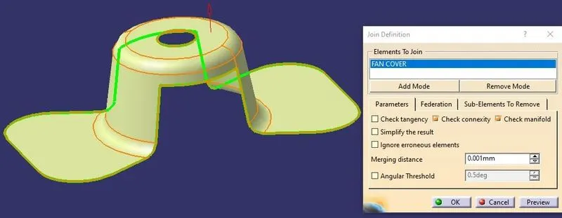
It is visible from the above image that surfaces are continuous without any gaps in between them.
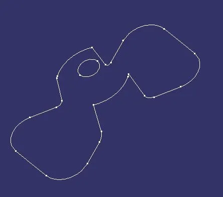
Here the boundary is further disassembling so that the continuity is clearly visible.
Step 2:
Second thing, we can find the tooling axis of the component. The tooling axis is created in the direction in which the core and cavity open. For that, we need to analyze the given component for the selection of suitable tooling direction.
- The selection of tooling direction depends upon the product and the feature of the product.
- The tooling direction is selected by visually checking the part and in such a manner that there is no need to incorporate the side core for the molding process. This ensures the proper clearance of the part removal after the process.
- The fan cover component has a hole on the top, hence it takes into consideration for the selection of the tooling direction.
- After visually checking in both directions (x & y), the Z direction is taken as a suitable tooling direction.
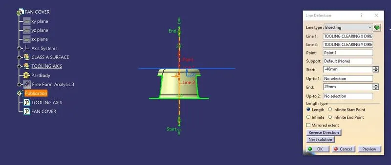
Here The bisecting method is used to find the real tool axis
- For this, to create a point on the center of the fan cover and insert the axis system as same as the axis system present at the origin. Create the dummy tooling axis in the Z-direction.
- After that intersecting the ZX plane with the fan cover, then we will get the two curves.
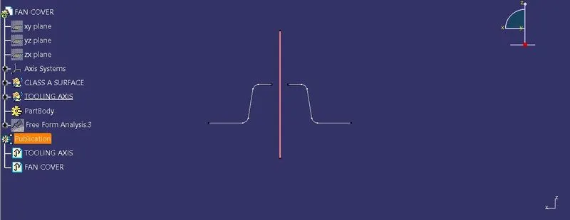
- We have to check the surface lines that are perpendicular to the tooling axis and these line doesn’t create any problem.
- The parallel lines to the tooling axis are the ones, we have to make the point to point surface lines to check the intersection of the surface line with the tooling axis.
After this, we have to bisect the two surface lines and select the bisecting line in the vertical direction. The line of the axis will be our tooling axis of X-direction.
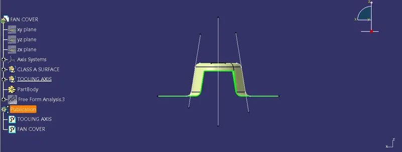
Similarly, we will follow the same procedure for the Y-direction tooling axis by intersecting the YZ plane of the axis system.
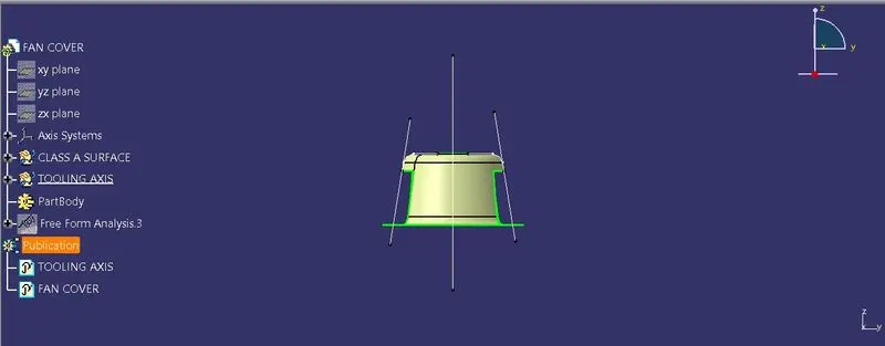
To get the final tooling axis we can bisect the Tooling axis of X-direction and the Y-direction.
Step 3:
After creating the tooling axis, we need to publish it using the publication option.
For that, we need to go for the insert option and then click the publication option then the dialogue box pop up, in that we have to select the Class-A surface and Tooling line and click ok.
Step 4:
Draft analysis:
- First, we have to change customize the view mode to Material mode.
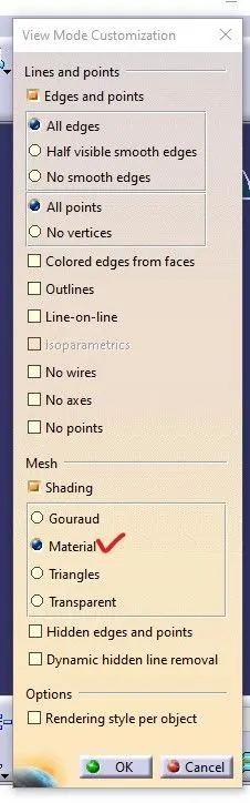
2. Now go to insert menu < Analysis < Feature draft analysis.
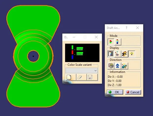
Now the draft analysis tool will appear on the screen and give the information about color-coding, Display, and Direction.
Mode:
The options enable us to give color coding and with the help of this, we can set the parameters of the draft analysis and also change the draft value if required for analysis.
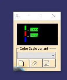
Display:
- The first option is used to hide and show the color code.
- The second option is used for analysis under point, it gives the value of draft with concern to the tooling axis at a given point of the surface after alignment of compass to tooling axis.
Direction:
We have to align the compass with the tooling axis to define the new current draft direction on tooling, once the compass is set on the tooling axis we have to lock it by enabling the option and clicking on anywhere on the surface and draft direction does not change.
Also, we can flip the direction of the draft by clicking on the inverse draft direction option when it is not in our tooling direction.
Quick Draft Analysis mode is shown below:
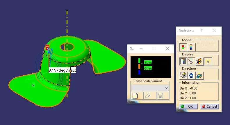
As shown in the above picture, it observes that all surfaces are in green color and it indicates that all surface has given the draft more than 3 degrees along the tooling direction. Then the part can be easily ejected along the tooling direction and it can be tool able.
Draft Angle Shown in various Orientation:
Isometric view:
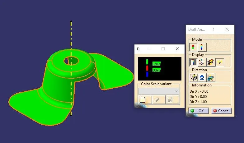
Front View:
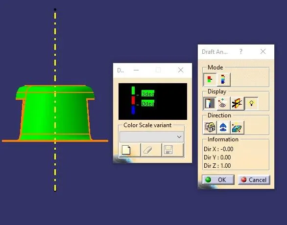
Side view:
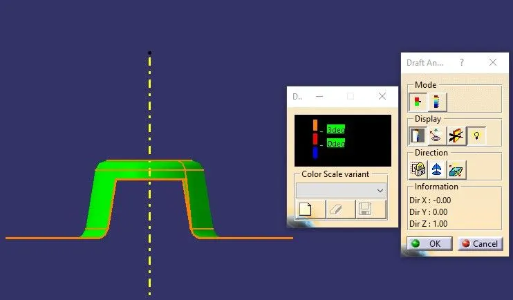
Top view:
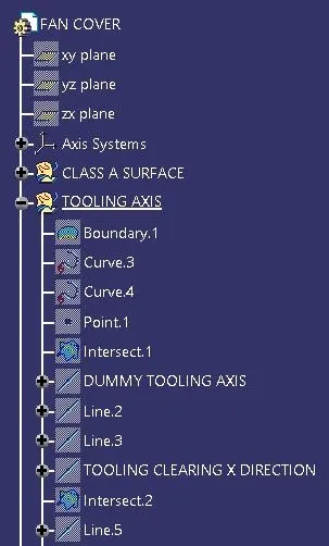
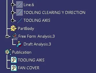
Tree diagram:
Conclusion:
The tooling axis is created for the given Class A surface model and the Draft analysis is performed in Catia V5 to make the component eligible for production with minimum cost and resolve the issues during the ejection process.