Week 9 - Attachment Feature Creation - Challenge 1
RIB CREATION ON THE COIN HOLDER
Aim:
To create an attachment feature Rib on the Coin Holder and consider the design rules and perform the draft analysis.
RIB:
- The Rib is an attachment feature for the Class-B surface to provide economical Stiffness and Strength in molded parts without increasing the wall thickness.
- Generally, Ribs are projected from the main wall in the mold-opening direction and are formed in blind holes of the mold steel.
- Rib also Facilitates:
- Locating and arresting components of an assembly.
- Provide a perfect alignment in the mating parts.
- Act as stops and guiding for mechanisms.
Design Rules for Rib:
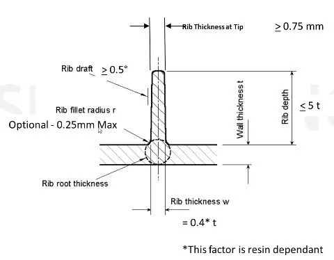
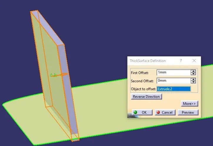
- The Thickness of Rib should be 40% of the component wall thickness to avoid the thick section at the wall base and reducing the amount of retained heat helps to prevent the Sink Marks. (w = 0.4*2.5 = 1mm)
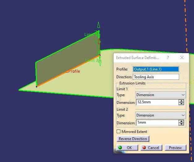
- The Height of the Rib should be less than and equal to 5 times the thickness of wall components because of the required draft for ejection, the top of tall ribs may become too thin to fill easily. (5*2.5 = 12.5 mm)
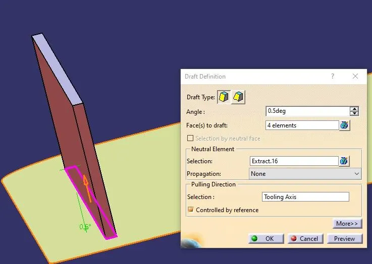
- The Draft should be provided as 0.5 degrees of draft per side to facilitate the part ejection from the mold. If it is more than 1 degree of draft per side, it can lead to excessive rib thickness reduction and filling problems.
- The Minimum thickness of Rib at the tip must be greater than 0.75 mm to provide the fast filling.
- The Fillet Radius of Rib should be 25mm maximum. If it is increasing, there will be a violation of the 40% thickness requirement.
- The Ribs should be spaced at a distance is at a Height/Width ratio and 3:1 is suitable. Distance will be considered as 5mm. Sometimes it will be 2 times the thickness of the component.
- The Rib Root Thickness will not exceed the factor that 30% of the component thickness. It means that it will not cross the value of more than 30 percent of thickness or less than 30 percent of component thickness. (1.3*2.5 = 3.25mm)
Creation of Ribs:
- Extract the lower surface of the coin holder.
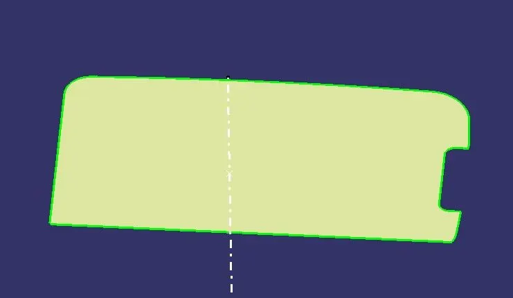
- Draw the sketches on it as shown in the figure and make it an output Feature.
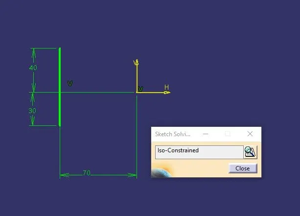
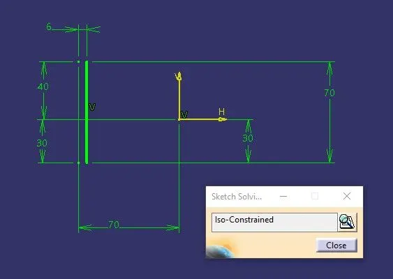
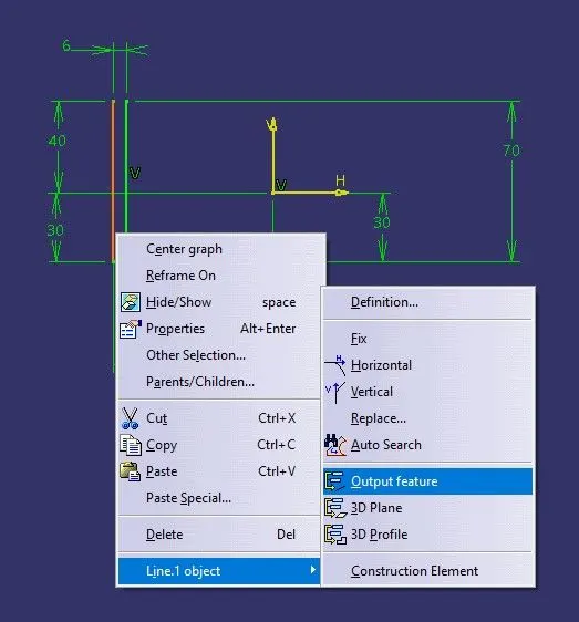
- Make an extrude surface along the tooling direction of 12.5 mm distance.
- Thicken the surface by 1mm using the thick surface command in part workbench and convert into solid body.
- Apply the draft as 0.5 degrees to the solid body.
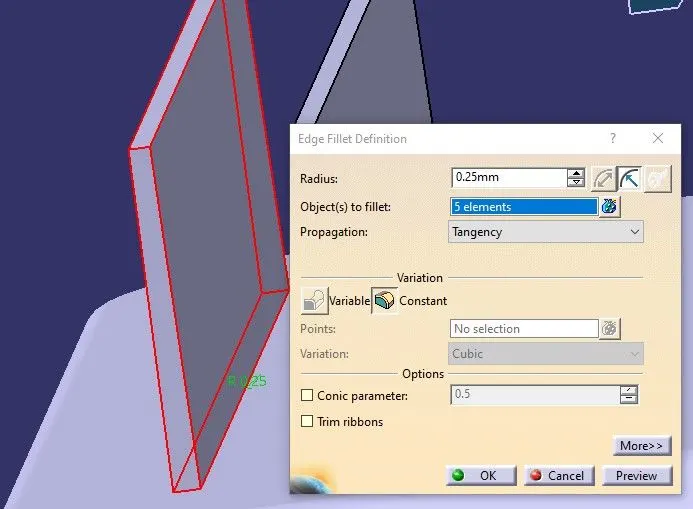
- Add the solid body into the main body and apply the fillets to ribs as 0.25mm.
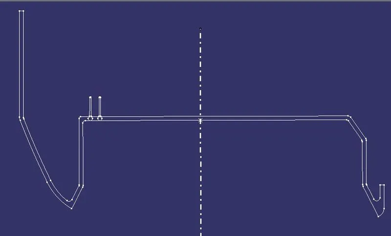
- The spacing of two ribs should give the 5mm.
- For the root analysis, intersect the body with the XY plane. Then we get
- Draw a tri-tangent circle with outlines of the ribs and base surface, the dimension is shown below.
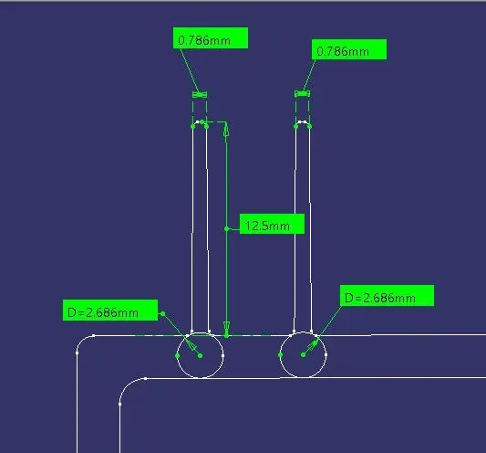
- Here the Rib root thickness is not exceeding the design value which is 3.25mm. This shows that the sinkhole does not go to form on the opposite side of the Rib.
- Dimension shown in the above picture are:
0.786mm is the Rib thickness at the tip.
12.5mm is the height of the Rib.
Diameter, 2.686mm is the Rib root thickness.
Views:
- Isometric view
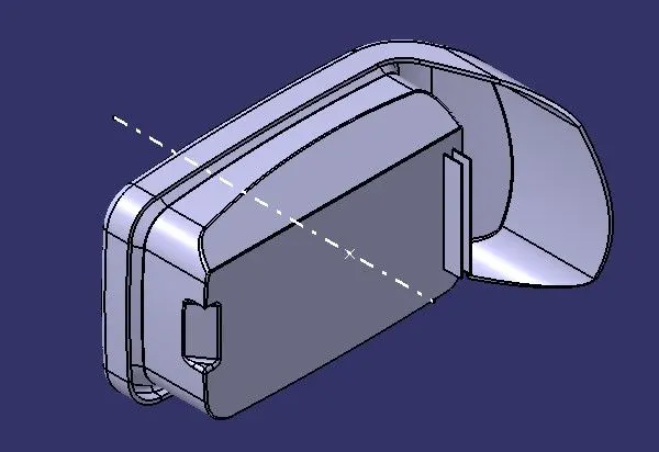
- Top view
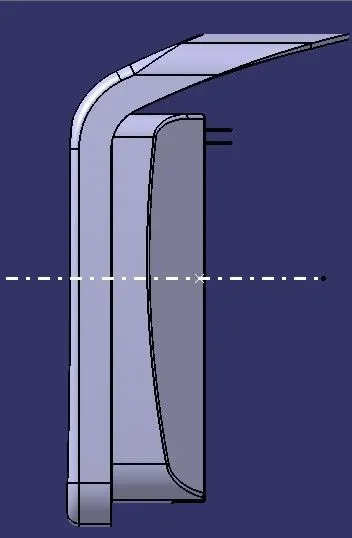
- Front view
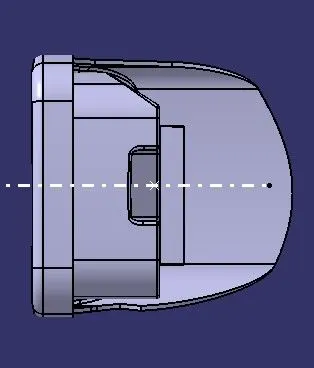
Draft analysis:
- Change the view customization mode to material mode.
- Go to the Insert menu and click on the analysis and then feature draft analysis.
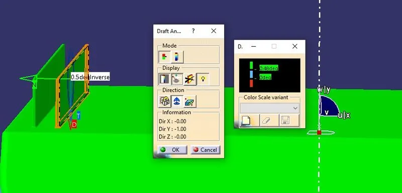
- Set the minimum draft value as 0.5 degrees for the Ribs.
- Align the compass with a tooling axis to define the new current draft direction.
- Then the analysis under running point placed at the surface of ribs, shows the 0.5 degrees and it appears in green color as mentioned in the color scale.
- This shows that the ribs are cleared with draft analysis, and it is easily removable from the mold without any damage.
Conclusion:
The Design of the attachment feature Rib on the Coin Holder by considering the design rules and performed the draft analysis.