Week 8 - Challenge 2 - Base Bracket Design
Design and Draft Analysis of Base Bracket
Aim:
To Create the tooling axis for the given class-A surface by Bisecting method to meet the requirement of draft angle and also create a Base Bracket Plastic component through the given Class-A Surface and perform the draft analysis on the created model to check if the model has provided with the draft to every area of the model.
Objective:
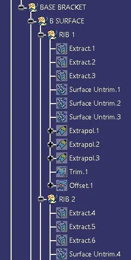
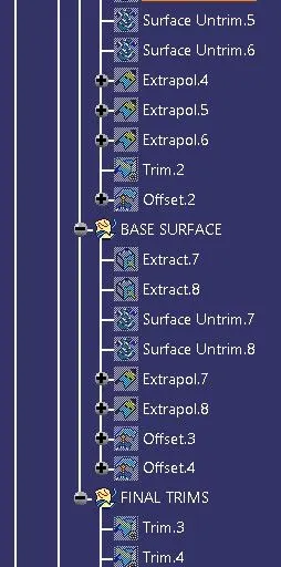
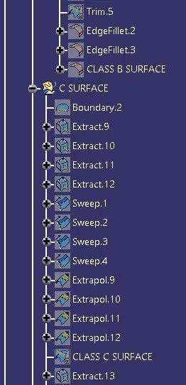
- To ensure the proper tree structure is followed.
- Geometric sets should have a proper name based on the sketches present inside of them.
- All the sketches should be created under the Geometrical set.
- Use the publication option and publish the Tooling axis and Class A, B, and C surface.
Procedure for creating the Base Bracket:
We need to check the connectivity of the given Class-A surface using the Boundary option. Ensure that there is no gap between any two surfaces.
Tool Axis Creation:
we have to create the tooling axis for the base bracket to provide the required draft angle for the ease of the ejection of the product.
- we have to check the plastic component visually and find that the Z direction is suitable for creating the tooling axis.
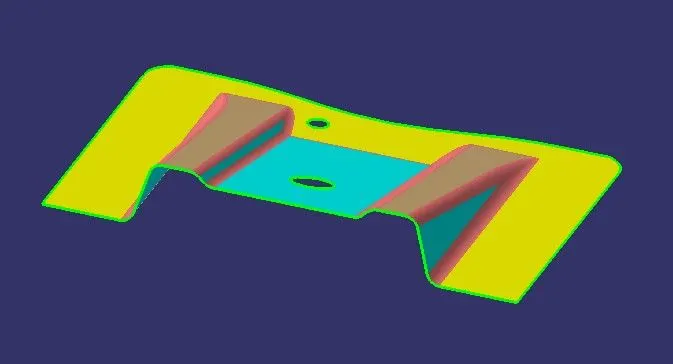
- First, we have to create a point on the center and the new plane is inserted on the point concerning the YZ direction and create a dummy tooling axis.

- Now intersect the YZ plane with the product, then we get the two curves.
- Draw the two-line on the curve in which may get the trouble further on the edges that they are parallel to the dummy tooling axis.
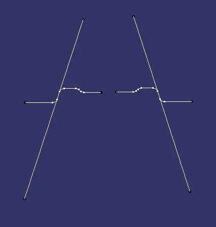
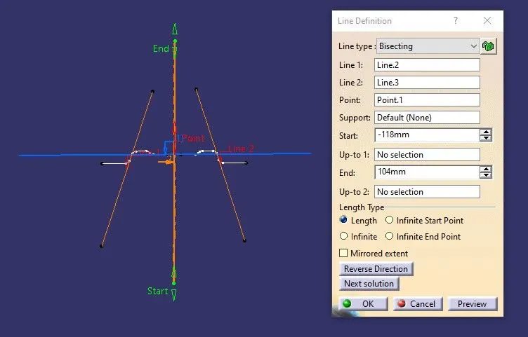
- Bisect the two lines then we get the main tooling axis and publish it.
Class B Surface Creation:
Consider the thickness of the plastic component is 2.5 mm. We have to create the class B surface as same as the Class A surface with an offset value of 2.5 mm.
First, we have to create the ribs, for that, we have the extract the surfaces of the rib from the class A surface and un-trim it and further extrapolate at a distance 0f 10mm them with point propagation and trim them to get the required surface. After that offset the extrapolate surface to a distance of 2.5mm. Follow the same procedure for the other rib creation.
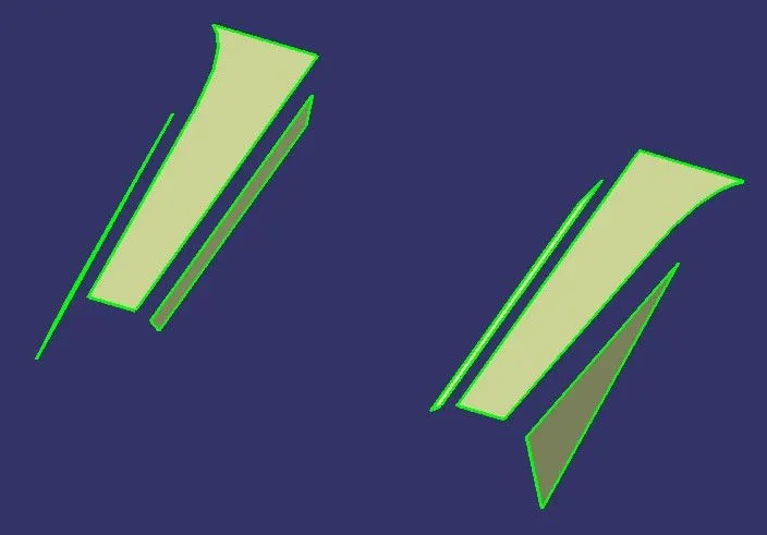
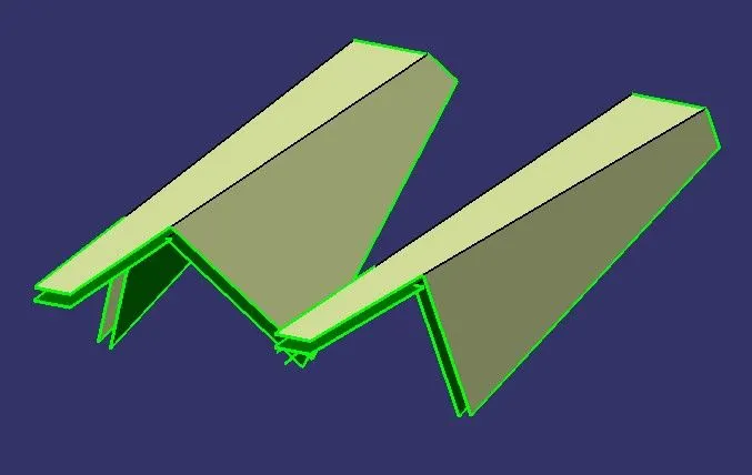
Now extract the base surface and un-trim it and further extrapolate and trim it to get a required surface and apply the fillet value and the created B surface as shown below.
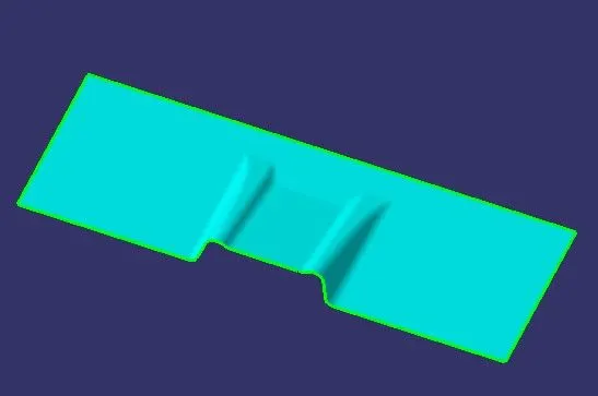
Class C Surface Creation:
Make a boundary line for the class-A surface by using the Boundary option and extracting it. Separate the whole curve into 4 small ones.
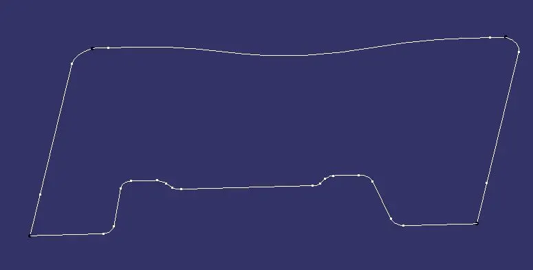
The C-Surface is created with a sweep option with a given draft angle and distance value. For that we go to Surface toolbar < Sweep < Profile type < line < Sub Type < With draft direction < Guide curve 1 – (select the extracted boundary) < Draft direction – (select tooling axis) < angle as 3 degree and 5 mm as length. Click ok.
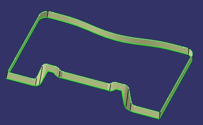
For holes, Extract the boundary of holes and sweep them to form the surface.
Finally, join the Class A surface with Class C surface and two holes. Trim the B Surface with joined one to get the closed surface of the Base Bracket and further it will form into solid.
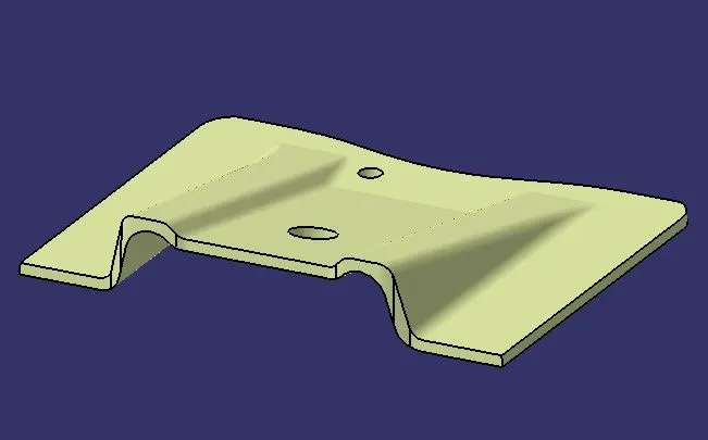
Closed Body Creation:
For the solid body creation of the surface body, Switch into the part workbench and use the closed body to make the surface solid.
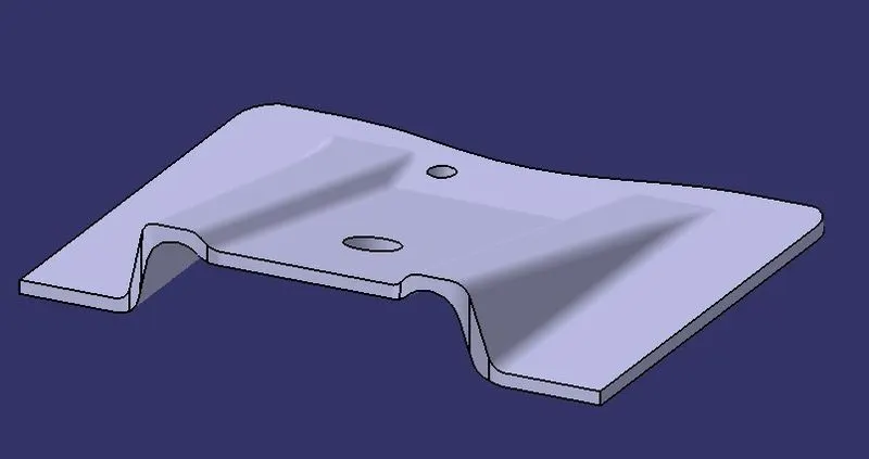
Draft Analysis Procedure:
To perform the draft analysis, we have to keep the customized view into the Material Mode.
Then go to insert < Analysis < Feature draft analysis. Now the draft analysis tool will appear on the screen and give the information about color-coding, Display, and Direction.
We have to align the compass with the tooling axis to define the new current draft direction on tooling, once the compass is set on the tooling axis we have to lock it by enabling the option and clicking on anywhere on the surface and draft direction does not change. The class A and C surface turn into the Green Color, it states that it will be given a 3-degree draft concerning tooling direction and it can be tool able.
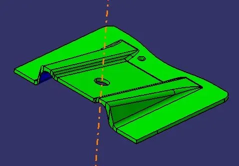
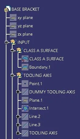
To publish the Class A, B, C Surface and Tooling Axis a using publication option on the Tool menu and it will be shown in the tree diagram.
Tree diagram:

conclusion:
The tooling axis was created by using Bisecting method and created the Class B and C surface and performed the Draft Analysis for Class A and C surfaces.