Explicit Dynamic Analysis on a Car
Explicit Dynamic Analysis on Car Crash
Aim :
- To perform Explicit Dynamic Analysis on Car Crash Model.
Objective :
- To define appropriate materials for the Car Crash Model.
- To perform symmetry operation.
- To define the Body-Interaction connection between them.
- To perform mesh on a Car Crash Model.
- To define appropriate Boundary Conditions to the Model.
- To request outputs for Total Deformation, Von-Mises Stress, Equivalent Elastic Strain.
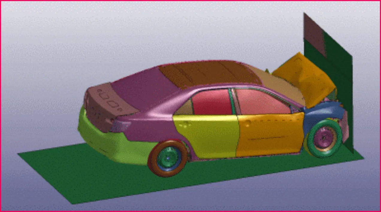
| Figure 1-Car Crash Animation. |
Procedure :
Phase 1- Material Set-Up :
- To set up the material for the Worm Gear Model. First, drag and drop the transient structural analysis workspace into the project schematic from the analysis system. This is shown in below Figure 2.
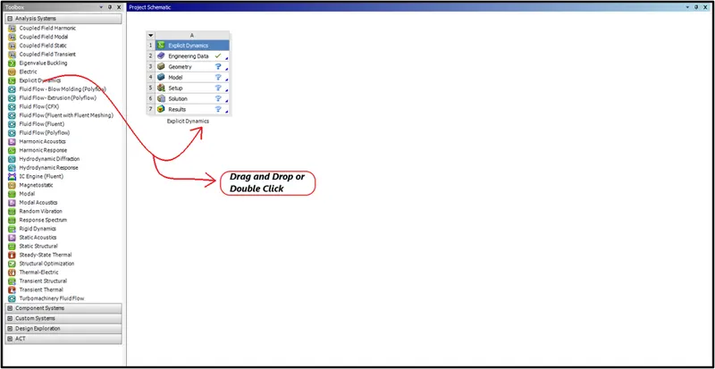
| Figure 2-Ansys Workbench Workspace. |
- After deploying the Explicit Dynamic analysis system in the project schematic workspace.
- Define the Engineering Data and geometry, To define the Geometry and Engineering Data, Right Click on the Engineering Data and click to edit, it will take to the Engineering Tab.
- There Right Click on the Material Tab, A window will Pop-Up stating Engineering data sources.
- Click on the Engineering Data Sources, There go and select the material to define the engineering data. This is shown in Figure 3,4,5.
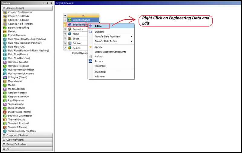
| Figure 3-Right Click on the Engineering Data. |
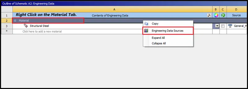
| Figure 4-Right Click on the Material Tab. |
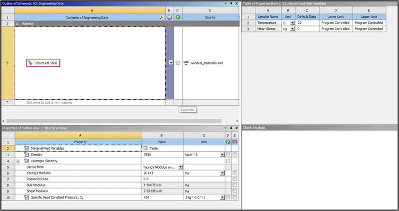
| Figure 5-Select Structural Steel as Material to define the Model. |
Phase 2-Geometry Set-Up :
- Next set up the geometry. To set up the geometry, Right-Click on the Geometry option >> Import Geometry. This is shown in below Figure 6.
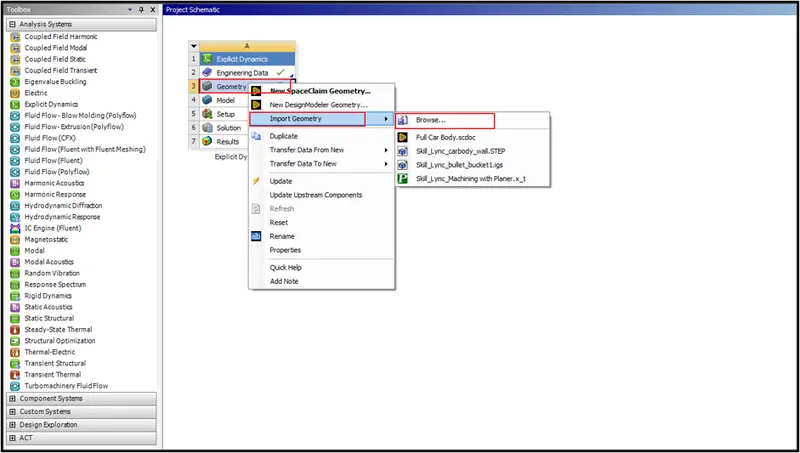
| Figure 6-Importing Geometry. |
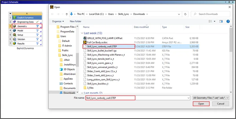
| Figure 7-Selecting the Geometry to Import. |
- Next double click on the geometry to check, Whether the model imported, is a Bullet Penetrating on a Bucket Model or not. Space Claim Workspace will open. The model will be imported in the space claim, Which is shown in below Figure 8.
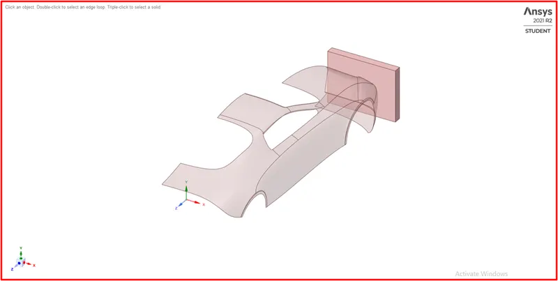
| Figure 8-Car Crash Model in the Space Claim. |
Phase 3-Model Set-Up :
- Next, define the model, Double click on the model, The Mechanical Workspace will open, There go and define the material, set up the load case for the model.
- The Model loaded in the mechanical workspace is shown in below Figure 9.
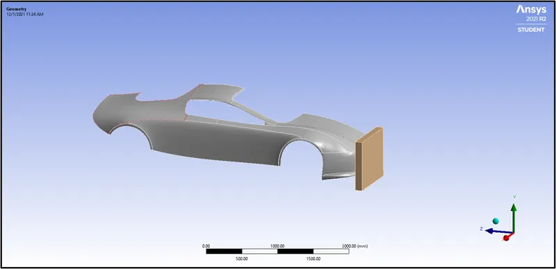
| Figure 9-Model Loaded in Mechanical Workspace. |
3:1 Assign Material :
- Next, define the material as Structural Steel for both Wall and Car, which is shown in below Figure 10.
- To assign a material, Click on the Geometry >> Select the Wall and Car Geometry >> Parameter Window >> Assignment >> Structural Steel.
- The mechanical properties of the material are shown in below Figures 11.
- Case-1 0.5 Thickness for the Car Body.
- Case-2 0.6 Thickness for the Car Body.
- Case-3 0.7 Thickness for the Car Body.
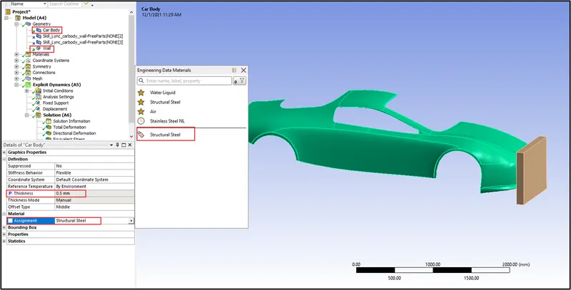
| Figure 10-Defined Material and Thickness for the Model. |
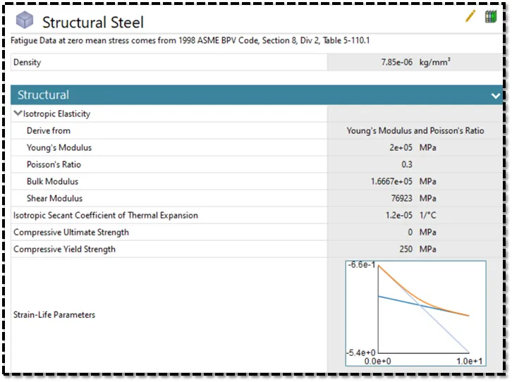
| Figure 11-Mechanical Properties of Structural Steel. |
3:2 Define Symmetry Region :
1) Wall :
- Select the rectangular cross-section of the wall and define the symmetry region for the wall, Which is shown in below Figure 12.
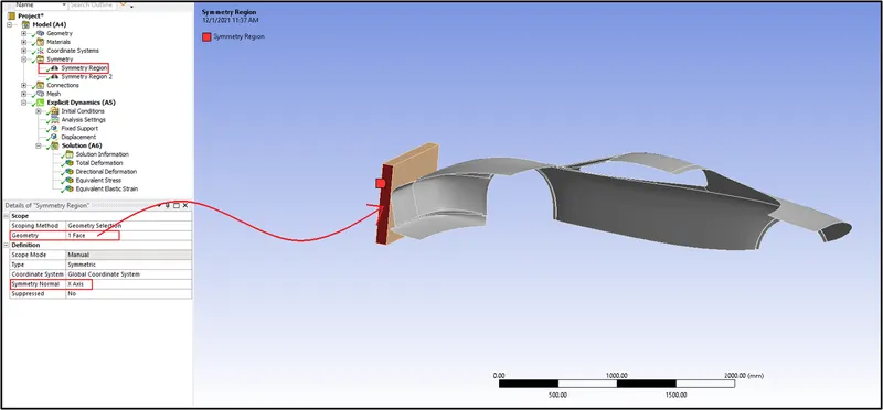
| Figure 12-Defined Symmetry Region for Wall. |
2) Car Body :
- Select the edges of the car body and define the symmetry in X-axis, Which is shown in below Figure 13.
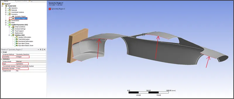
| Figure 13-Defined Symmetry for Car Body. |
3:3 Define Connections :
- Here for explicit dynamics, The connection will be the Body-Interaction connection, This is only suitable for Explicit Dynamics.
- Within an Explicit Dynamics analysis, the body interaction feature represents the contact between bodies and includes settings that allow you to control these interactions.
- If the geometry you use has two or more bodies in contact, a Body-Interaction object folder appears by default under Connections in the tree. Included in a Body Interactions folder are one or more body-Interaction objects, with each object representing a contact pair.
3:4 Meshing :
- After defining the connections, We have to define mesh for the Car Crash Model.
1) Patch Conforming Method :
- Select the wall with a solid filter and give the method as tetrahedrons, Which is shown in below Figure 14.
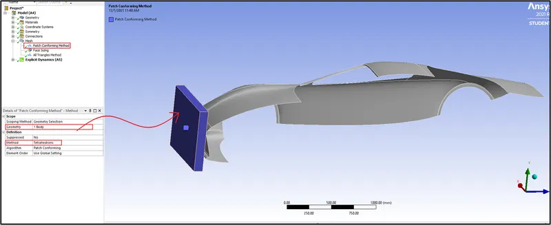
| Figure 14-Patch Conforming Method. |
2) Face Sizing :
- Select the faces, which are not having contact with the wall.
- Mesh with the 300 mm element size, Cause it will reduce your computational time, If you mesh the model with fine mesh, then it will take one day to solve, so mesh the model with coarse mesh.
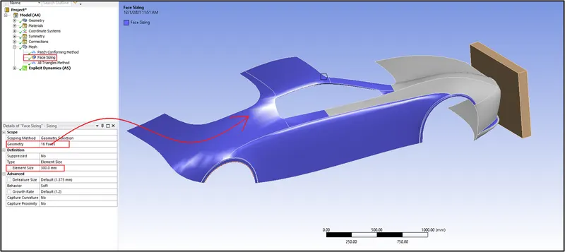
| Figure 15-Face Sizing. |
3) All Triangles Method :
- Select the car body with the solid filter and give the method as triangles and generate the mesh, Which is shown in below Figure 16.
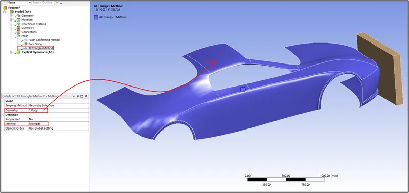
| Figure 16-All Triangles Method. |
3:5 Analysis Settings :
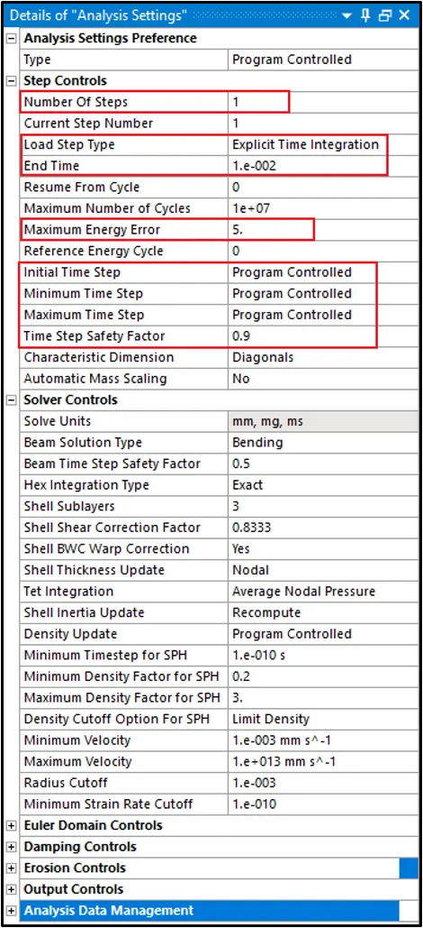
- Here for this Car Crash Model, No of steps given for this simulation is 1.
- Number of Steps-1.
- Load Step Type-Explicit Time Integration.
- End Time-0.01 sec.
- Maximum Energy Error- 0.1.
- Initial, Minimum, and Maximum Time Steps --Program Controlled.
- Time Step Safety Factor- 0.9.
- Keep other parameters and options as it is the default.
| Figure 17-Analysis Settings. |
3:6 Boundary Conditions :
- After giving some parameters in the analysis settings, We have to give boundary conditions.
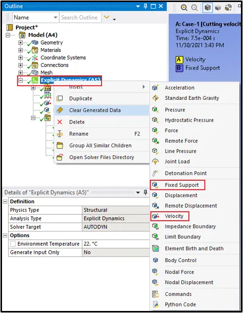
- Here we have to create two boundary conditions, We have to give Velocity and Fixed Support.
- To give Joint Rotation, Right Click on the Explicit Dynamics >> Insert >> Velocity, Fixed Support. This is shown in below Figure 18.
| Figure 18-Give Displacement and Fixed Support. |
1) Fixed Support :
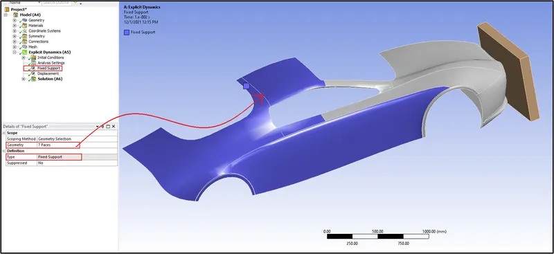
- Here select the faces of the car and give fixed support, cause the wall will be hitting the car, So fix the car and give fixed support. This is shown in below Figure 19.
| Figure 19-Defined Fixed Support. |
2) Displacement :
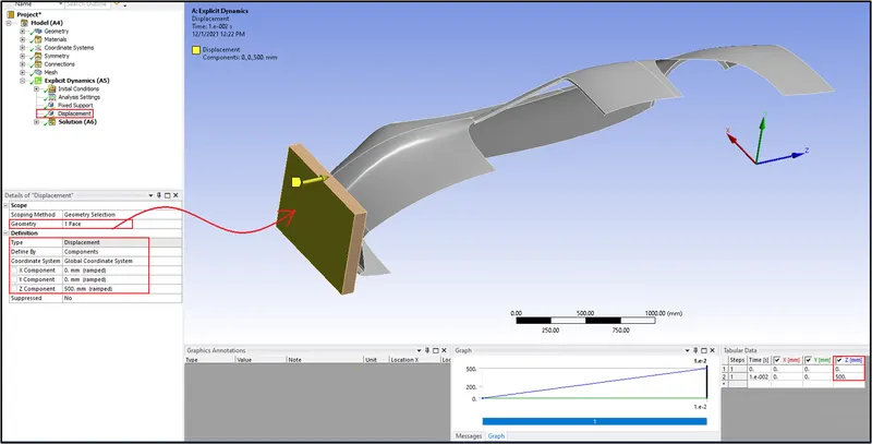
- Select the face of the wall and provide the displacement along the positive Z Direction with the magnitude of 500 mm. Which is shown in below Figure 20.
| Figure 20-Defined Displacement. |
Phase 4-Request for the Outputs :
- Here we have to request outputs for the VonMisses Stress, Strain, and for Total Deformation.
- To request Output for Stress,Right Click on the Solution >> Insert >> Stress >> Equivalent Von Misses Stress.
- To request Output for Strain,Right Click on the Solution >> Insert >> Strain >> Equivalent Von Misses Strain.
- To request Output for Total Deformation,Right Click on the Solution >> Insert >> Deformation >> Total Deformation.
- This is shown in below Figure 21.
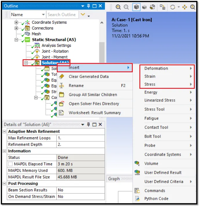
| Figure 21-Requesting Outputs for the Stress, Strain, and Deformation. |
- Next request output for the contact.
- To request Contact Tool >> Right Click on the Solution >> Insert >> Contact Tool >> Pressure >> Status,Which is shown in below Figures 22 and 23.
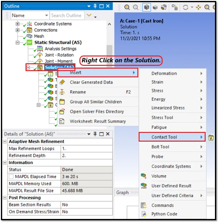
| Figure 24-Requesting Output for Contact. |
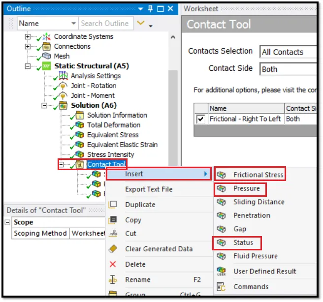
| Figure 25-Requesting Outputs for Contact Tool. |
- Similarly request the output for the probe.
- The Output requested for the Car Crash Model is shown in Figure 26.
- After requesting all the outputs, Run the Simulation.
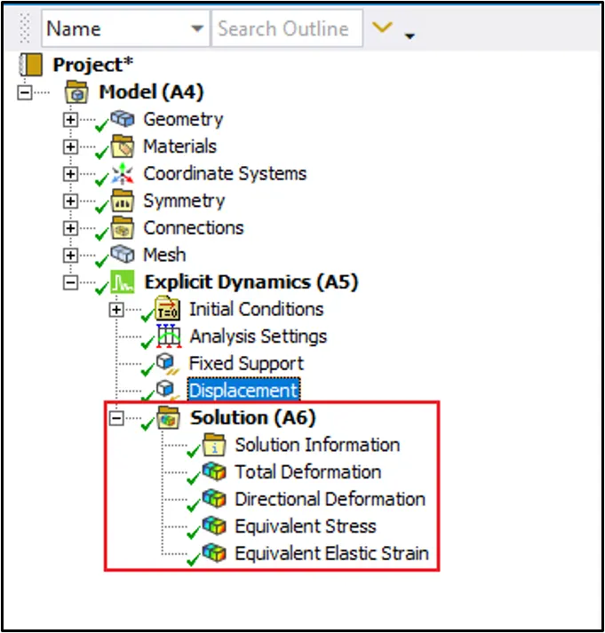
| Figure 26-Required Outputs Requested. |
- To run the simulation, Right Click on the Solution >> Solve. This is shown in below Figure 27.
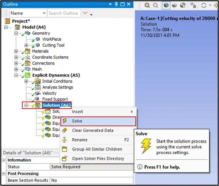
| Figure 27-Solve all the Outputs Requested. |
- After solving the outputs requested, the simulation results for all two cases are shown below Figures.
Parameters :
- For this crash model, We will be defining parameters, The parameters are used to save the file size.
- Instead of creating a load case for every case, we can give parameters and run the simulation, It will save our time.
- Make sure to enable the parametric study in the Ansys workspace.
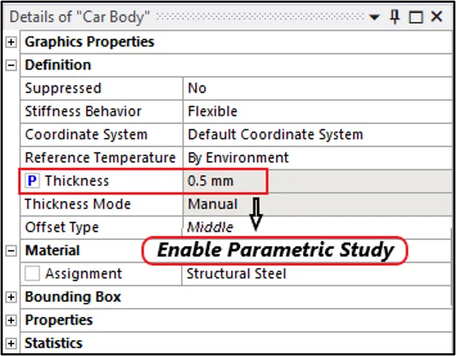
| Figure 28-Enable Parameters. |
[Note: Make sure to enable the parametric study in the outputs requested, Like Equivalent Von-Misses Stress, Equivalent Elastic Strain and Total Deformation, Enable parametric study in all the outputs, what we have requested.]
Equivalent Von Misses Stress :
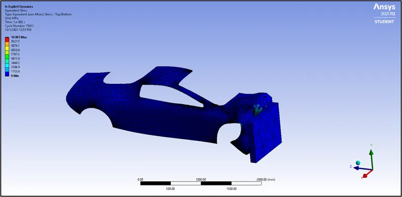
| Figure 29-Equivalent Von-Misses Stress. |
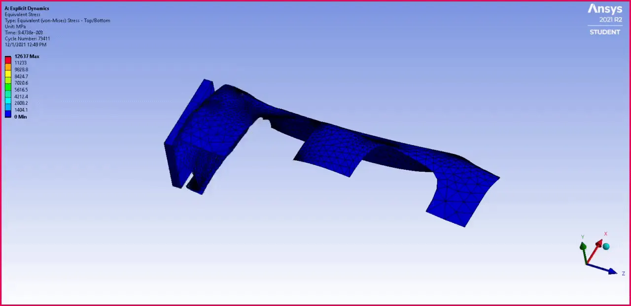
| Figure 30-Equivalent Von-Misses Stress Simulation Animation. |
Equivalent Elastic Strain :
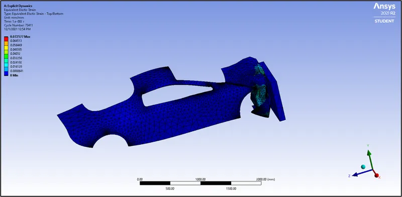
| Figure 31-Equivalent Elastic Strain. |
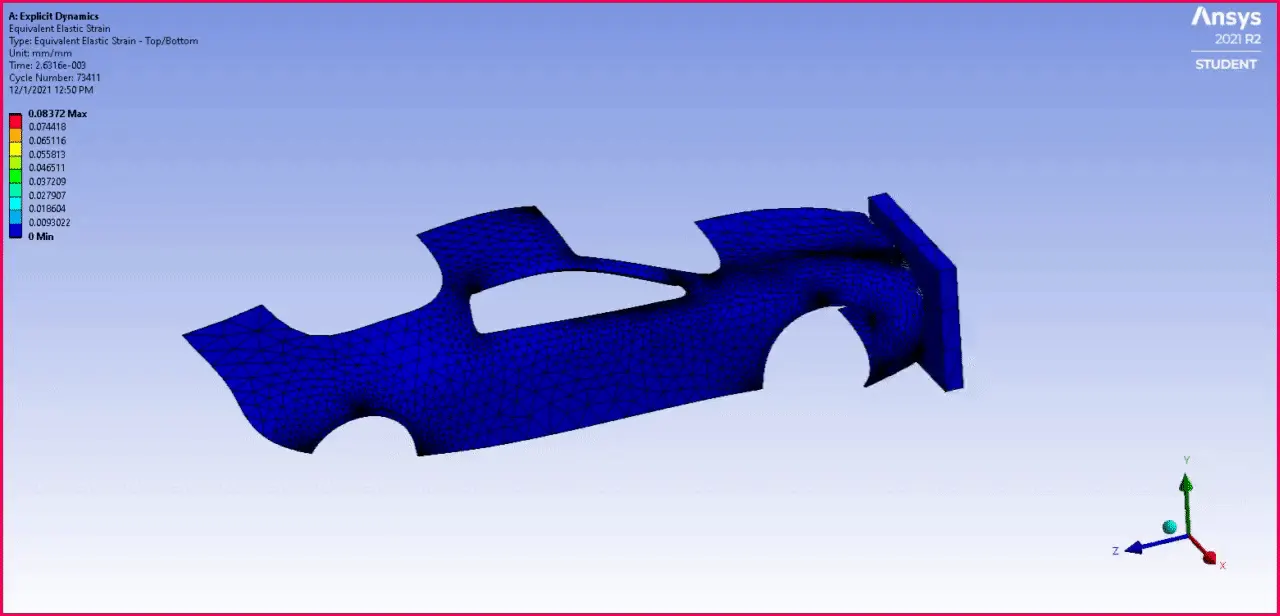
| Figure 32-Equivalent Elastic Strain Simulation Animation. |
Directional Deformation :
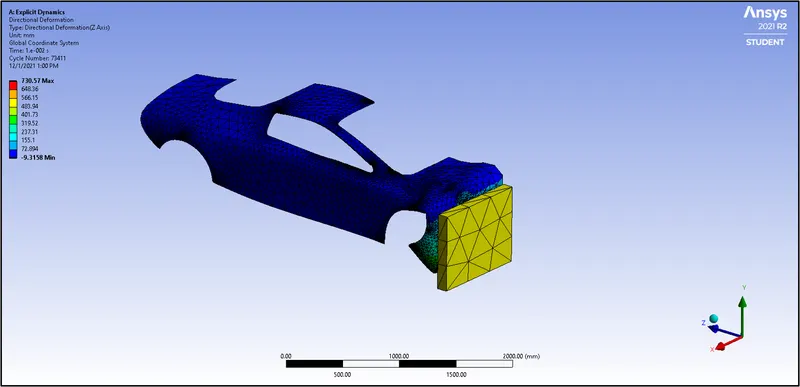
| Figure 33-Directional Deformation. |
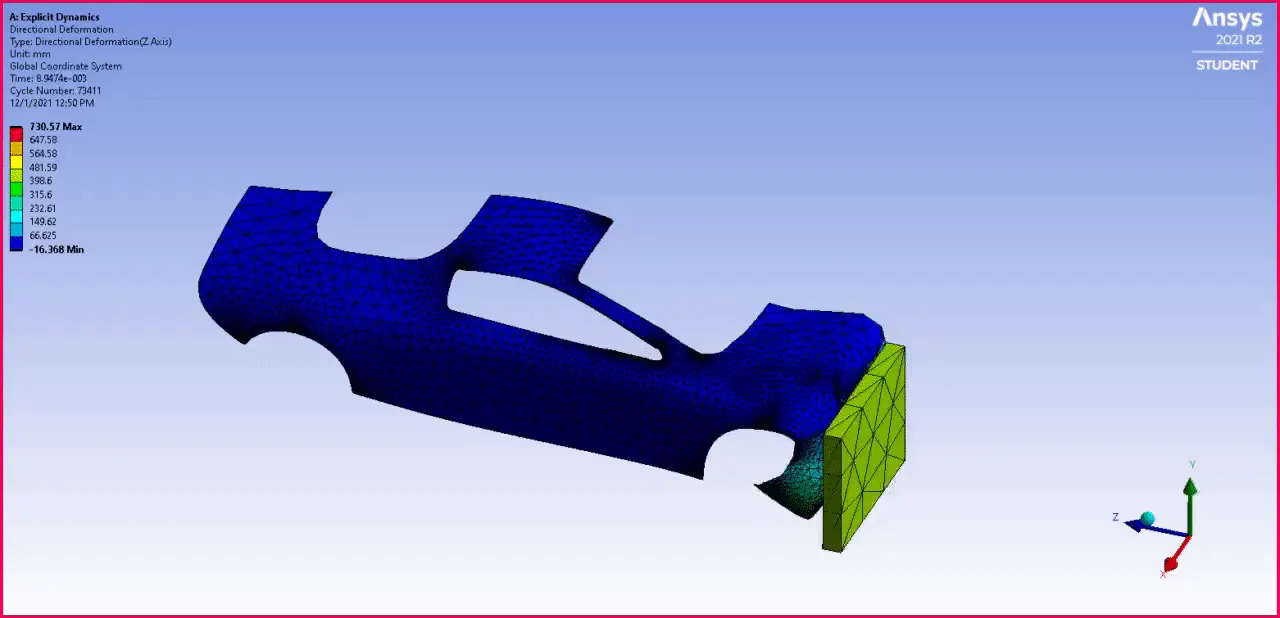
| Figure 34-Directional Deformation Simulation Animation. |
Total Deformation :
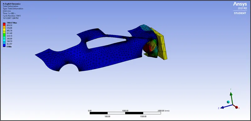
| Figure 35-Total Deformation. |
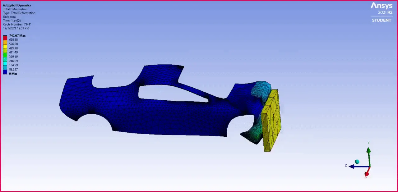
| Figure 36-Total Deformation Simulation Animation. |

| Figure 37-Parameter Chart for 3 Cases. |
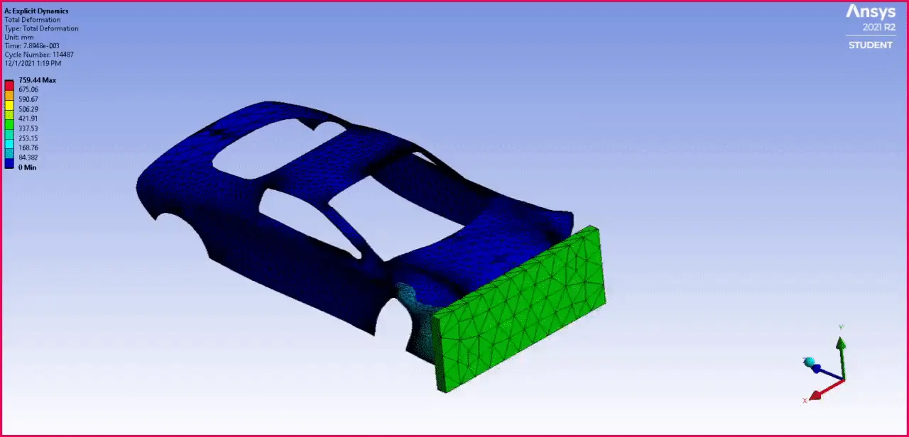
| Figure 38-Full Car Crash Simulation. |
Results :
|
Cases |
Equivalent Von-Misses Stress (MPa) |
Equivalent Elastic Strain (mm/mm ) |
Directional Deformation (mm) |
|||
|
Max. |
Min. |
Max. |
Min. |
Max. |
Min. |
|
|
Case-1 (0.5 mm Thickness) |
10381 MPa |
0. MPa |
7.2577e-002 mm/mm |
0 |
730.57 mm |
-9.3158 mm |
|
Case-2 (0.6 mm Thickness) |
17092 MPa |
0 MPa |
0.11382 mm/mm |
0 |
754.87 mm |
-7.2496 mm |
|
Case-3 (0.7 mm Thickness) |
15417 MPa |
4.4861 MPa |
0.1081 mm/mm |
0 |
751.95 mm |
-2.8641 mm |
| Table-1 |