Solid Meshing [Tetra Mesh] of a Car Rear View Mirror
Solid Meshing [Tetra Mesh] of Car Rear View Mirror
Aim -
- To do a pre-processing on Car Rear View Mirror using ANSA Software [Version 19.1.4].
Objective -
- To check the geometrical errors on the Car Rear View Mirror model.
- To Provide Mesh Parameters and Quality Criteria.
- To generate 2D mesh on the surfaces based upon the quality criteria given in the question.
- To generate 3D mesh [Volume Tetra Mesh] on the component given.
- Check the elements,if they are failing for tet collapse.
Theoretical Frame Work -
- A rear-view mirror or rearview mirror is a flat mirror in automobiles and other vehicles, designed to allow the driver to see rearward through the vehicle's rear window (rear windshield).
- In cars, the rear-view mirror is usually affixed to the top of the windshield on a double-swivel mount allowing it to be adjusted to suit the height and viewing angle of any driver and to swing harmlessly out of the way if impacted by a vehicle occupant in a collision.
- The rear-view mirror is augmented by one or more side-view mirrors, which serve as the only rear-vision mirrors on trucks, motorcycles and bicycles.
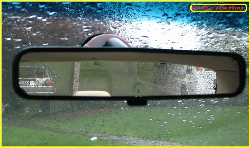
| Figure 1-Rear View Mirror. |
Intro to 3D Meshing and Some Terminologie's -
3D Element Types-
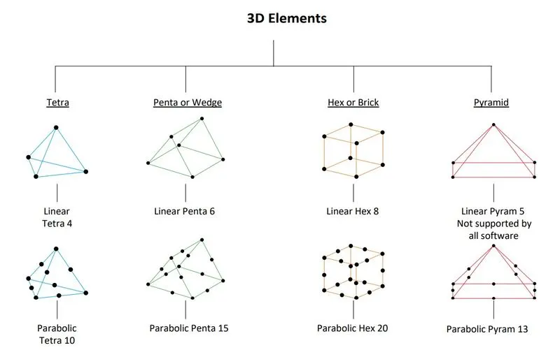
| Figure 2-3D Element Types |
[Note:Penta and Pyramid element's are rarely used.But parabolic element's are very very rare element's only used for 1 or 2 specific types of condition's.]
Shell Element-
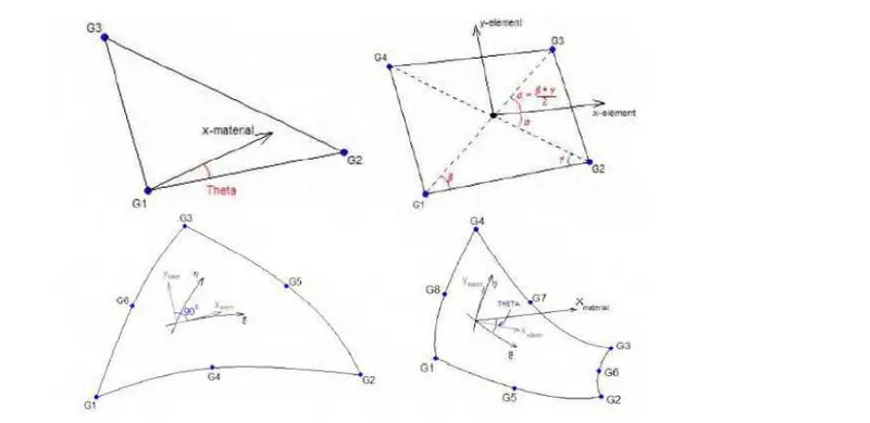
| Figure 3-Shell Element's |
Example of shell elements (CTRIA3, elements (CTRIA3, CQUAD4, CTRIA6, CTRIA6, CQUAD8)
- First Order 4 or 3 nodes.
- Second Order 6 or 8 nodes.
- DOFs 6 degrees of freedom per node.
Solid Element-
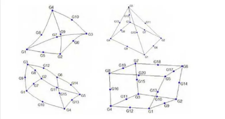
| Figure 4-Solid Element's |
Example of tetrahedron tetrahedron, pyramid, penta and hexa elements elements
- First Order 4, 5, 6, 8 nodes.
- Second Order 8, 12, 15, 20 nodes.
- DOFs 3 degrees of freedom per node.
Two Types of Solid Meshing -
1) Hexa Mesh [Structured Mesh]
- Structured meshes are meshes with implicit connectivity whose structure allows for easy identification of elements and nodes. Often structured meshes have orthogonal quadrilateral (2D) or hexahedral (3D) elements.
- Structured meshes allow programmers to enumerate the nodes in such a way that any adjacent elements or nodes can be called upon without knowing any connectivity information.
- It is also possible to access coordinates easily because the size of each element does not vary element to element.
| Figure 5-Structured Mesh. |
2) Tetra Mesh [UnStructured Mesh]
- Unstructured meshes are meshes with general connectivity (GCON) whose structure is arbitrary and therefore the connectivity of elements must be defined and stored.
- GCON element types are non-orthogonal, such as triangles (2D) and tetrahedra (3D).
- Unstructured meshes require programmers to map more data to each node, such as adjacency lists and coordinate lists.
| Figure 6-UnStructured Mesh. |
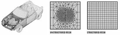
| Figure 7-UnStructured and Structured Mesh. |
Structured mesh advantages -
- Memory efficient
- Fast to Solve
Unstructured mesh advantages -
- Complex geometries easier to mesh.
- Arbitrary positions.
Structured mesh disadvantages -
- Angled and curved geometries are approximated (leads to stair stepping).
Unstructured mesh disadvantages -
- Greater memory requirement.
- Slower to solve.
Different meshes -
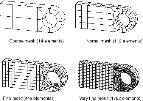
| Figure 8-Different Meshes. |
Procedure -
Phase 1-Importing the CAD Model
- Hence we are importing a given CAD geometry into the ANSA.
- There are file formates like IGES,STEP,Parasolid where we can import these file formats into any CAD,CAE Softwares.
- In ANSA we can import all the CAD Software file formates like
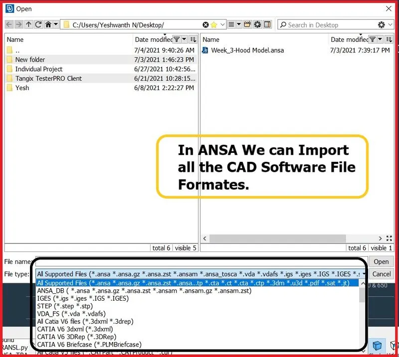
| Figure 9-Supported File Formats. |
- IGES [Initial Graphics Exchange Specification].
- STEP [Standard for the Exchange of Product Model Data].
- Solidworks.
- Catia V5,V6
- Simens NX CAD
- Inventor
- Creo
- Solid Edge
- Rhinoceros 3D
- IGES,STEP,These two are standard file formats which are mostly used in industries.But now a days in industries,they are aslo using parasolid file format.
- Now import the model into ANSA GUI.The Model given to us is in STEP File Format.
- Go to Main Pull Down Menus >> File >> Open.
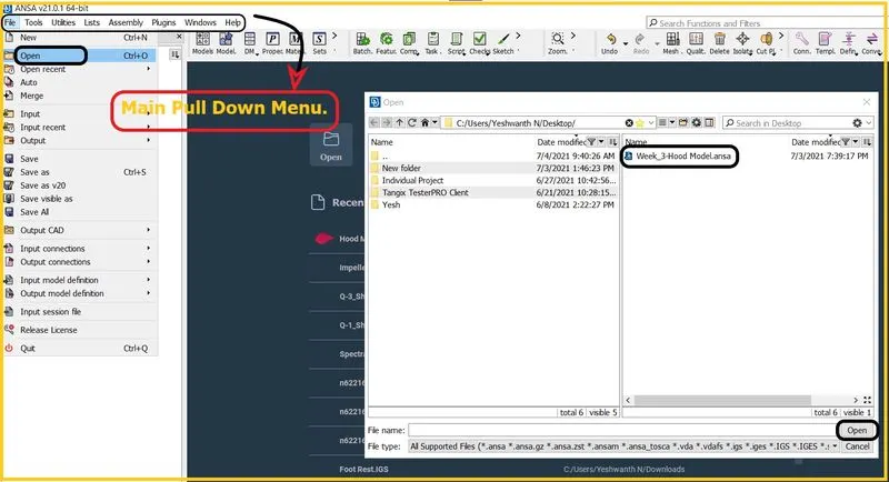
| Figure 10-Importing/Opening the Model. |
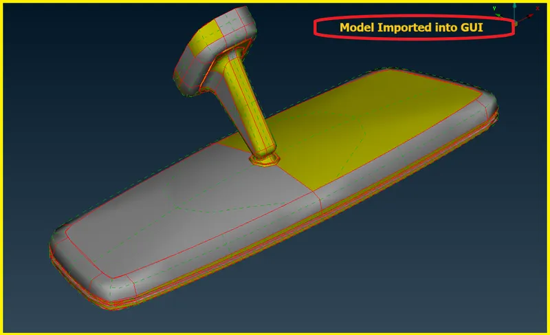
| Figure 11-Model Imported in to GUI. |
Phase 2-Initial Check
- Before working on the model.There are single cons present in the model.There is no connectivity in the model after importing.
- We have to do topo on the model by window selection.
- After that the cons will be connected.
- To do Topo.Go to Topo Module >> Faces >> Topo >> Window Selection on the model.
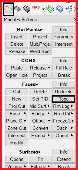
| Figure 12-Mesh Module. |
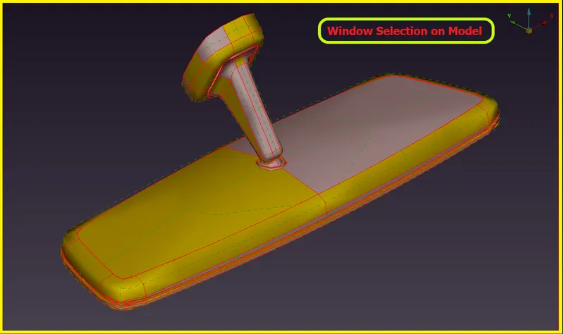
| Figure 13-Window Selection. |
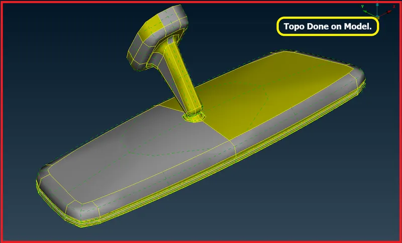
| Figure 14-Topo Done on Model. |
- We have to check the geometry if there are any errors like
- Damaged Geometry.
- Free edges in unnecessary areas.
- Unnecessary points on the lines.
- Unnecessary Connections and connectivity error.
- By assessing the Rear View Mirror model there are no errors in the geometry.
- If there are any unnecessary properties in the property browser,Delete them and then proceed.
- We have to do some geometry clean up on the model,Cause there will be some minimal errors in the model.To solve that we should do some geometry clean up on the model.
Phase 3-Geometry Clean Up
- Here we will be doing some geometry checks on the parent component.
- We have to fix the geometrical errors in the parent component,Then only we will be able to extract midsurface.
- To fix the geometry checks go to Tool Bar >> Checks >> Geometry.
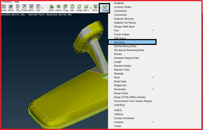
| Figure 15-Checks Manager. |
- After clicking on the check geometry,The geometric errors will be displayed.
- We can fix that geometric errors by manually or automatically.
- For this hood model,We can fix that errors automatically by auto fix.
- While checking for errors in the geometry make sure to check this options in the checks manager.
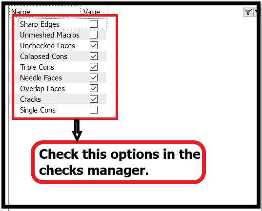
| Figure 16-Check Geometry Options. |
Terminologies for Geomerty Options -
- Unchecked faces - Faces that failed for the shadow operation.
- Needle Faces - Degenerated faces are faces that have their opposite CONS coincident.
- Collapsed Cons - A CONS where it's starting and ending position coincide.
- Triple Cons - Areas where three or more faces have a common boundary.
- Cracks - Red CONS at inner areas.[Holes are excluded].
- Single Bounds - Red CONs at outer areas.[Holes included].
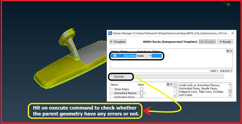
| Figure 17-ANSA Check Manager. |
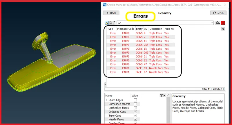
| Figure 18-Geometric Errors. |
- Here in the Checks window all problems are reported with red color.
- Under Description column the kind of problem is explained.
- Focus functions are available in order to isolate geometrical problems and handle them easier.Select to fix all or specific reported problems by pressing right mouse button on the header of the list or one or more highlighted problems.
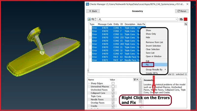
| Figure 19-Fixing Errors. |
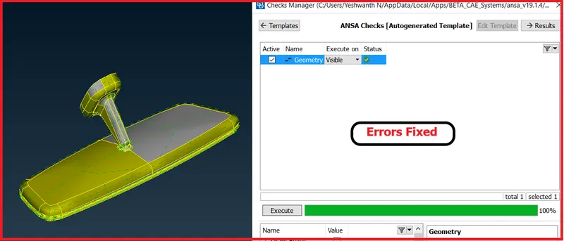
| Figure 20-Errors Fixed. |
- [Note: All problems except triple CONS can be fixed by the automatic fixing.]
- [Note: Right mouse clicking on Check Geometry line, performs an action to all listed problems.In case where not all problems are fixed automatically, retry or proceed to fix them manually.For this component no need to fix manually because all the errors have been fixed with auto fix.]
Phase 4 - 3D Meshing
4:1 What is 3D Mesh ?
- A 3D mesh consists of finite elements with each element defined with specific physical properties.
- This 3D mesh is used for analysis, in various domains such as static structural analysis, dynamic modal analysis, thermodynamic analysis, etc.,
- Any 3D modelled object with a specific volume and dimension can be 'meshed' with a finite number of elements that helps in solving for accuracy in pin-pointing regions of strain at a higher resolution.
- We will do 3D Mesh for the components,whose thickness have more than 8mm.
- Before generating a mesh,give the mesh parameters and quality criteria.
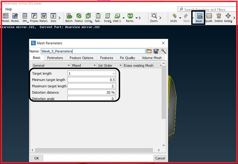
| Figure 20-Mesh Parameters. |
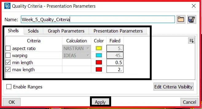
| Figure 21-Quality Criteria. |
[Note : Save the Mesh Parameter and Criteria file for that component and save it in any other drives,Cause whenever we open that component,we can open the Element Criteria file and Parameter file,So criteria and mesh paremeters will be applied habitually instead of entering again.]
- In ANSA we can only use one method called 2D to 3D Mesh Conversion.
-
Start Meshing
- To begin mesh,Switch form topo module to the mesh module.
- Before Meshing set the perimeter and macro length to the component.
- Here set the perimeter and macro length as target element size.
- It will split according to the target element size,So it will be easy for us to mesh.
- To Mesh >> Go to Mesh Module >> Mesh Generation >> Spot Mesh >> Select the area.
- While Meshing Switch from shaded mode to the hidden mode,Then only we will be able to see the visibility element quality.

Figure 22-Drawing Styles Panel.
- By Assessing the rear view mirror model,They are four components called
- Spherical Bearing
- Mirror
- Mirror Frame
- Handle
- So start meshing the components one by one
1) Spherical Bearing Component [Shell Mesh]
- Now while meshing the component.
- Set the perimeter and macro length as target element size given,So it will split the hot points according to that length and it will be easy for us to mesh.
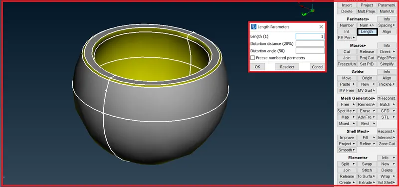
| Figure 23-Giving Length Parameters. |
- After giving length parameters
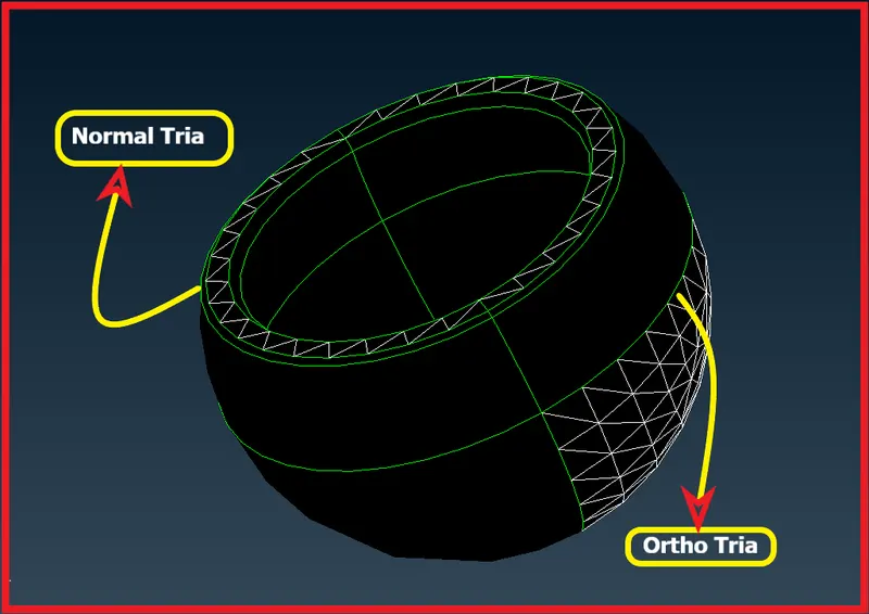
- Start meshing the component,In curved regions,Use element type as ortho tria and mesh,Cause it gives a proper feature capturing,So use ortho tria as element type in curved regions.
- In flat regions,Use normal tria as element type and mesh.
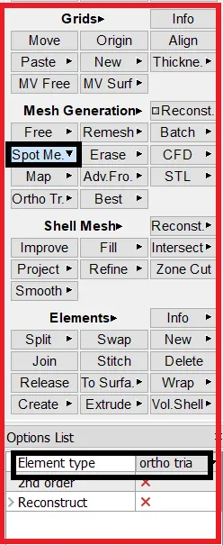
| Figure 24-Mesh Module. |
|
Figure 25-Ortho and Normal Tria. Ortho Trias-In Curved Surfaces. Normal Trias-In Flat Surfaces. |
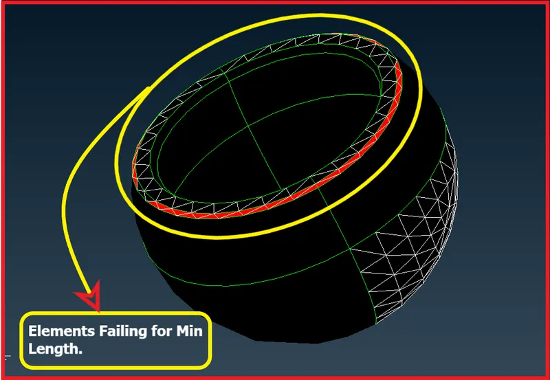
| Figure 26-Elements Failing. |
- To fix this failure,Extract a Midline in that hemming region and toggle rest of the two lines.
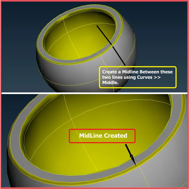
| Figure 27-Midline Created. |
- Now project the newly created curve to the surface by using project tool.Cons >> Project.
- And toggle the rest o the two lines and keep only the middle line.
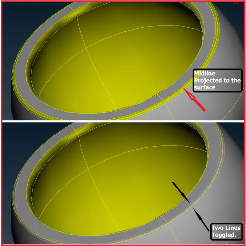
| Figure 28-Lines Toggled. |
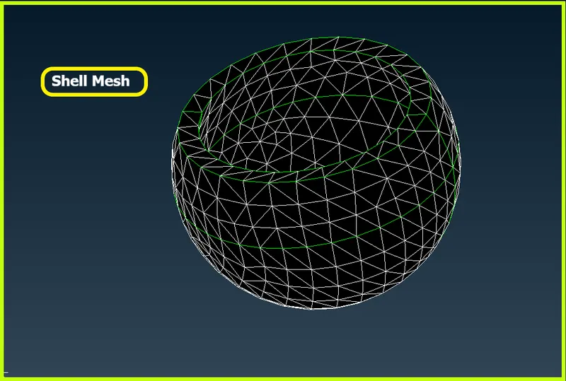
| Figure 29-Shell Mesh. |
- After shell mesh,Create a volume mesh on the component.
- Go to Volume Mesh Module >> Define >> Manual >> Window Selection >> Create New PSolid.
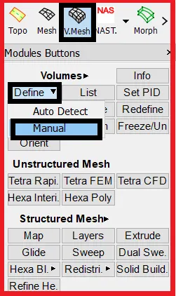
| Figure 30-Volume Mesh Module. |
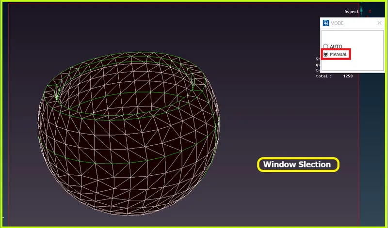
| Figure 31-Window Slection to create a volume. |
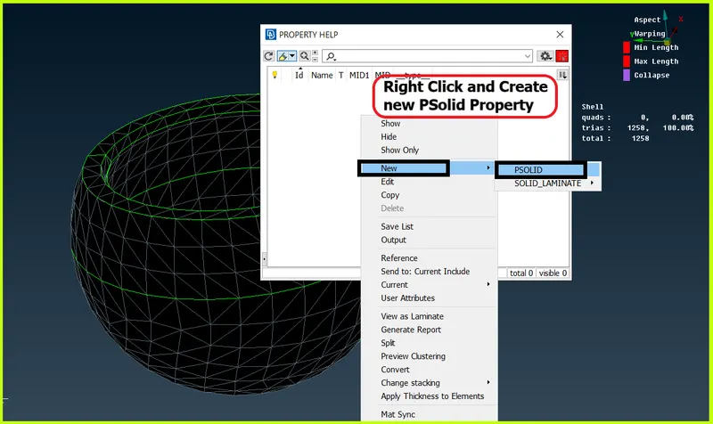
| Figure 32-Creating New Property Id. |
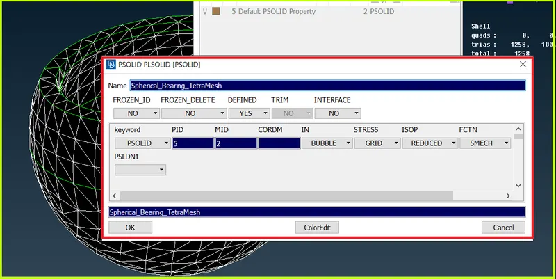
| Figure 33-Property ID Created. |
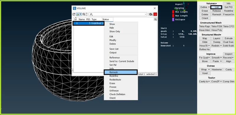
| Figure 34-ReMesh. |
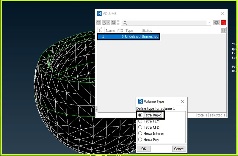
| Figure 35-Define the Mesh by Volume Type. |
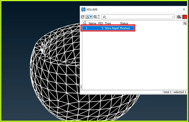
| Figure 36-Mesh Defined. |
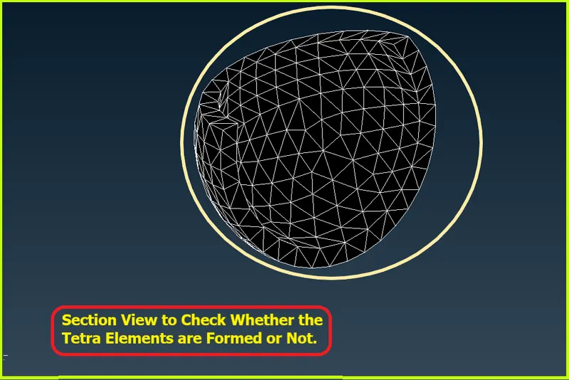
| Figure 37-Section View. |
- After creating volume tetramesh,check for the elements failing for tet collapse.
- Here there no elements failing for tet collapse.
4:2 Check whether the element's are failing for Tet Collapse
- In 2D Tetramesh,We will be checking whether element's are failing for only min and max length.
- In 3D Tetramesh,We will be checking whether element's are failing for only tetcollapse.
What is Tet Collapse ?
- Tet Collapse can be calculated by measuring the distance of a node from the opposite face, then each of the four values will be divided by the Square root of the opposite face's area. The minimum of four resulting values is then normalized by dividing it by 1.24.
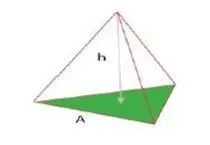
| Figure 38-Tet Collapse |
- Tetra elements whose collapse value falls below the value specified are highlighted when the tetra collapse function is selected.These elements remain highlighted until the Check Elems panel is exited.
- Tetra collapse calculation: At each of the four nodes of the tetra, the distance from the node to the opposite side of the element is divided by the square root of the area of the opposite side. The minimum value found is normalized by dividing it by 1.24, and then reported. As the tetra collapses, this value approaches 0.0. For a perfect tetra, this value is 1.0.
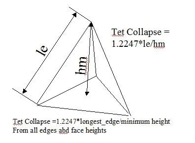
| Figure 39-Tet Collapse Formula |
- Simillarly do the same process for all the other three components.
2) Mirror Component -
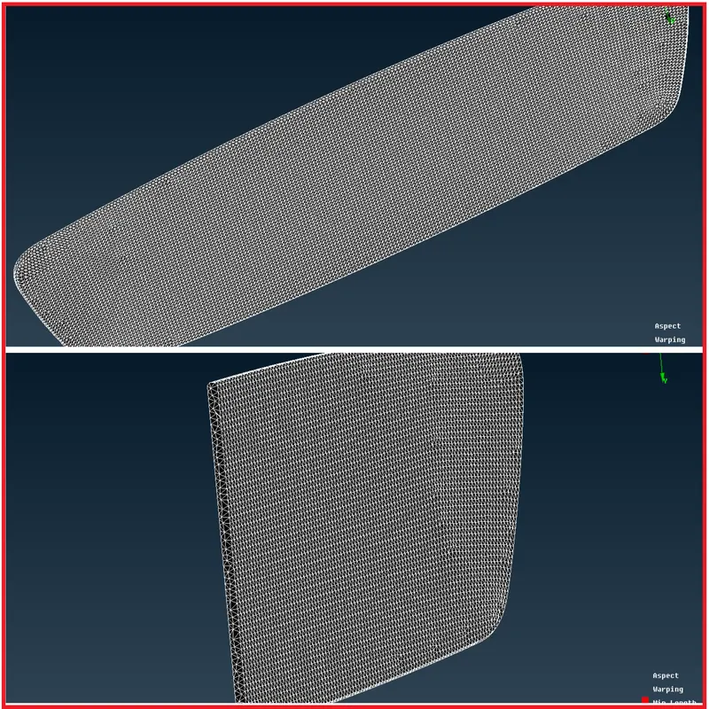
| Figure 40-Mirror Component. |
3) Mirror Frame Component -
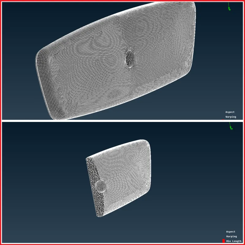
| Figure 41-Mirror Frame Component. |
4) Handle Component -
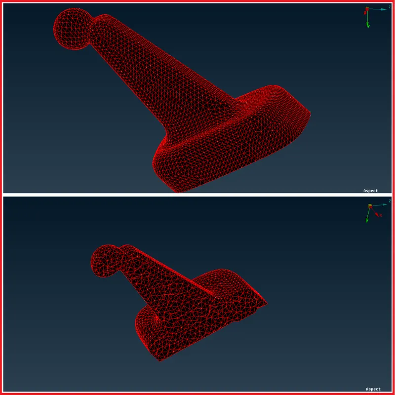
| Figure 42-Handle Component. |
Final CAD Model Image -
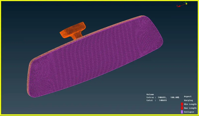
| Figure 43-Final Image 1 |
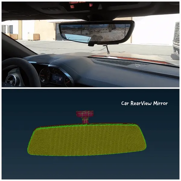
| Figure 44-Final Image1:1. |
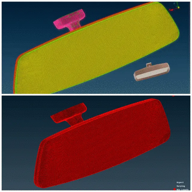
| Figure 45-Final Image 1:2. |
Result -
- Hence TetraMesh Generation Method-2D to 3D Conversion for Reaar View Mirror component with the following quality criteria has been done.
- Hence there are no surface deformations in the geometry.
- A well connectivity has been established between the surfaces.
- The features have been captured properly.
- A good mesh flow have been achieved with the zero elements failing for quality.
Learning Outcome -
- In this Week 5 Rear View Mirror Model Challenge,I came to know
- How to 3D mesh a component properly without dent's,kink's and raised edges.
- How to create a volume tetra mesh for the components.
- How to generate a proper mesh flow without kenks and dent's.
- How to fix the elements failing for the tet collapse.