Week 10: Project 1 - FULL HYDRO case set up (PFI)
Aim: To perform the Surface Preparation and boundary flagging on the IC Engine and setting up Full Hydro case setup -PFI Simulation.
Objective:
- To perform surface preparation and flag the boundaries on a given IC Engine case.
- Setting up Full Hydro case setup-PFI Simulation for the setup.
- To show the animation how all the valves and pistons move according to crank angles.
- To calculate the combustion efficiency of this engine.
- Using the engine performance calculator, determining the power and torque for this engine.
Theory:
Port Fuel injection is when fuel is injected prior to the valve and cylinder, where the combustion happens. The intake valve will have a fuel injection system that sprays fuel into the air coming into the engine. From there the spark plugs ignite the pressurized slurry of air and fuel, pushing the cylinder head down and spinning the crankshaft.
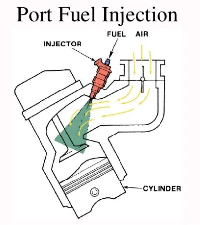
This project discusses the methods involved in Combustion and spray modelling in the port fuel injection engine. It is very important to study the mixture preparation in engines to understand the injection strategy which helps in achieving minimum emission and lower fuel consumption.
Geometry:
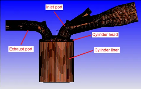
First import the geometry in converges. Once it is successfully done, perform the Diagnosis, It will display the Problem errors in geometry if anything is there.
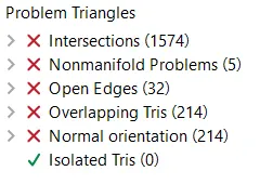
On running the diagnosis for the setup we seen there are many errors in the geometry, which does not allow us to run the simulation.
To overcome these errors we need to resolve this with the help of boundary flagging.
Boundary Flagging:
This helps us to clean the geometry more effectively, initially boundary flagging is done for all the parts, later once the surface preparation is done then we can re-adjust the boundary flagging.
Create Boundary flagging, Go to Geometry>Boundary>Flag>Create required boundary definitions.
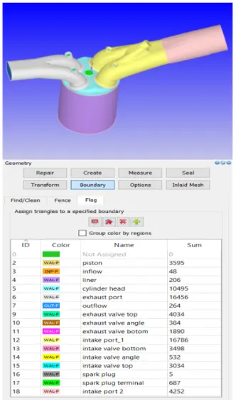
Piston and liner:
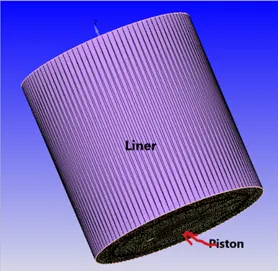
For selected the piston, select triangle method.
For selected the liner, mark the fence on top and bottom.
Cylinder Head:
Mark boundary fence at inlet and exhaust ports and mark fence at top of the liner.
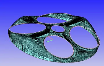
Spark plug and Spark terminal:
Select an arc surrounding spark plug and mark the fence and select it as boundary.
For Spark plug go to boundary, click on reconstruct fence from existing boundary.
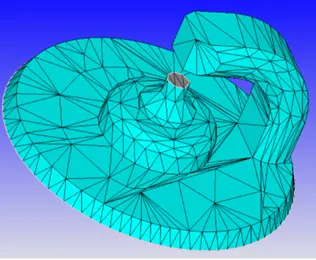
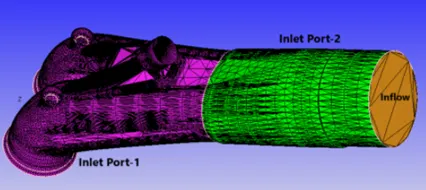
Inflow, Inlet port1, port2:
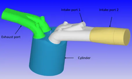
Divide the inlet port to Port1 and port2 for better initial conditions:
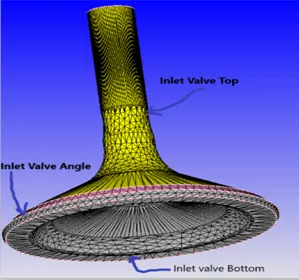
Inlet valve:
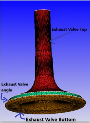
Valves are divided into three different part in converge i.e. is Top, Angle, Bottom. Because for provide the additional embedding at near valves.
Exhaust valve:
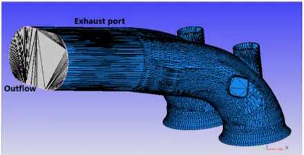
Exhaust port:
Surface Preparation:
In surface preparation, all the errors found during diagnosis are fixed perfectly so that it helps us o better results. Here on selecting the different problems from diagnosis window we can see where exactly the problem is in the geometry.
In order to proceed the simulation all the errors should be resolved. we try to remove the error at each step we need to run diagnosis and check if they resolved.
Error in Diagnosis:
Click on diagnosis and find the errors.
Intersection error:
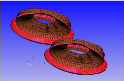
This error occurs because of inlet valve triangles overlapping with the inlet port1.
For rectify this error go to geometry-measure-direction-arc normal and select three point on arc.
Copy arc normal coordinates next go to geometry-transform-translate-select boundaries and copy the arc normal coordinates, translate inlet valve.
Non-Manifold Problems and Overlapping triangles:
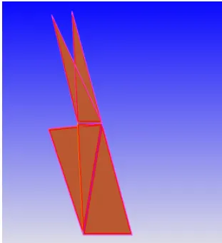
Single edge is shared by more than two triangles then that edge is called No manifold edge.
Select the overlapping triangles and delete them.
Open Edges:
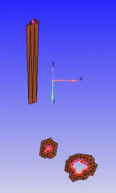
For open edges, select open edges and use patch option.
Normal Orientation:
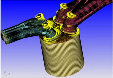
To eliminate this error, check the direction of normal vectors in same direction.
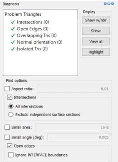
All surfaces cleaned and perform diagnosis:
Case setup:
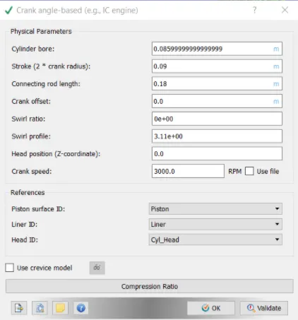
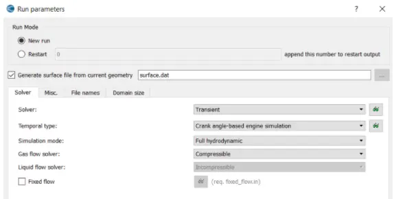
Application type: Crank angle-based IC Engine
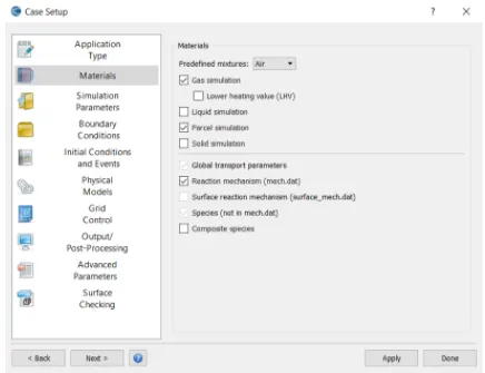
Materials:
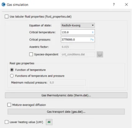
Gas Simulation: Therm.dat.file (import)
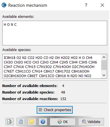
Reaction Mechanism: Mech.dat(import)
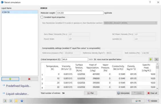
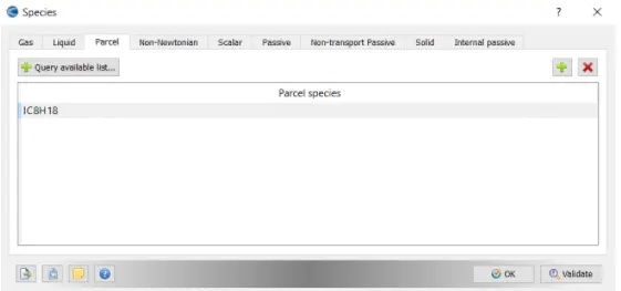
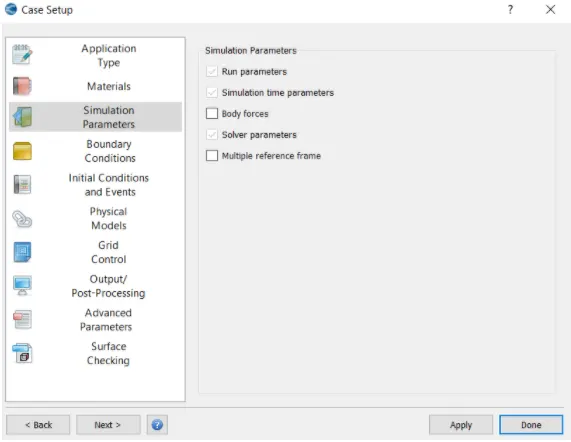
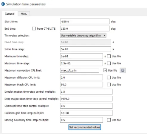
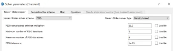
Simulation Parametrs:
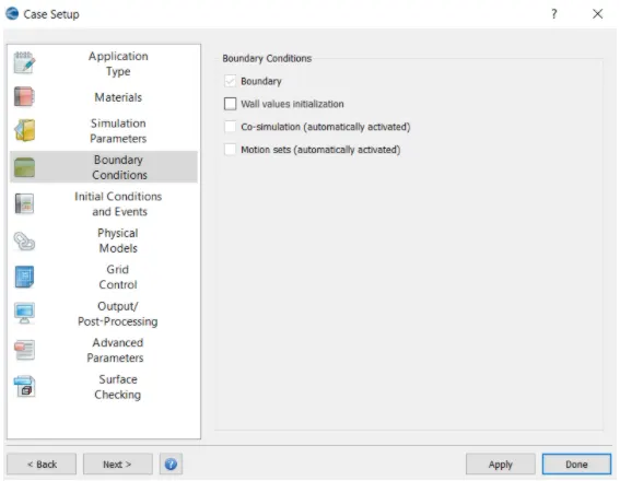
Boundary Conditions:
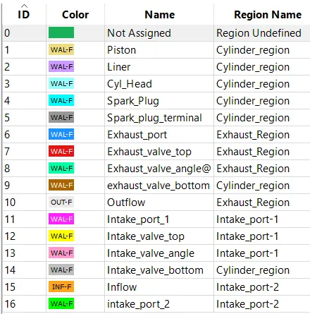
Piston:
Type : wall
Wall motion type : Translating
Surface movement : Moving
Temperature : law of wall (450K)
Liner:
Type : wall
Wall motion type : Stationary
Surface movement : Fixed
Temperature : law of wall (450K)
Cylinder Head:
Type : wall
Wall motion type : Stationary
Surface movement : Fixed
Temperature : law of wall (450K)
Spark Plug:
Type : wall
Wall motion type : Stationary
Surface movement : Fixed
Temperature : law of wall (550K)
Spark Plug terminal:
Type : wall
Wall motion type : Stationary
Surface movement : Fixed
Temperature : law of wall (550K)
Exhaust Port:
Type : wall
Wall motion type : Stationary
Surface movement : Fixed
Temperature : law of wall (500K)
Exhaust valve top:
Type : wall
Wall motion type : Translating
Surface movement : Moving, Profile: exhaust_lift.in
Temperature : law of wall (525K)
Exhaust valve angle:
Type : wall
Wall motion type : Translating
Surface movement : Moving, Profile: exhaust_lift.in
Temperature : law of wall (525K)
Exhaust valve bottom:
Type : wall
Wall motion type : Translating
Surface movement : Moving, Profile: exhaust_lift.in
Temperature : law of wall (525K)
Outflow:
Type : wall
Wall motion type : Stationary
Surface movement : Fixed
Temperature : law of wall (800K)
Pressure : 101325 pa
Species:
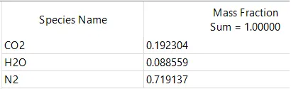
Intake Port_1:
Type : wall
Wall motion type : Stationary
Surface movement : Fixed
Temperature : law of wall (425K)
Intake Port_2:
Type : wall
Wall motion type : Stationary
Surface movement : Fixed
Temperature : law of wall (425K)
Inlet valve top, angle and bottom:
Type : wall
Wall motion type : Translating
Surface movement : Moving, Profile: intake_lift.in
Temperature : law of wall (480K)
Inflow:
Type : wall
Wall motion type : Stationary
Surface movement : Fixed
Temperature : law of wall (363K)
Pressure : 101325 pa
Species:
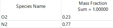
Regions and Initialization:
Stoichiometric reaction:

Cylinder Region:
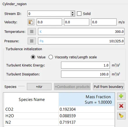
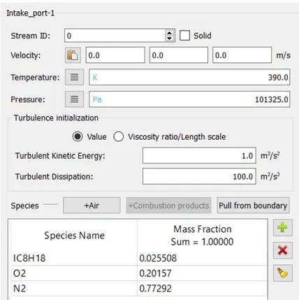
Intake Port_1:
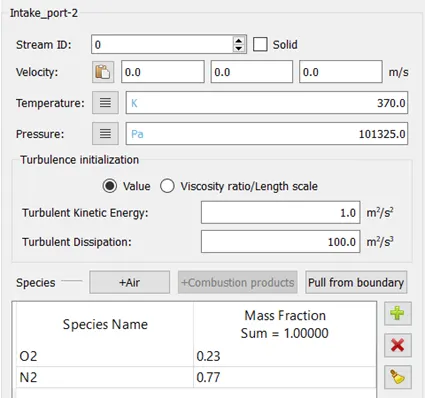
Intake port_2:
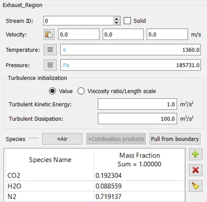
Exhaust region:
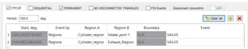
Events:

Physical Models:
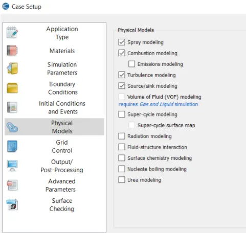
Spray Modelling:
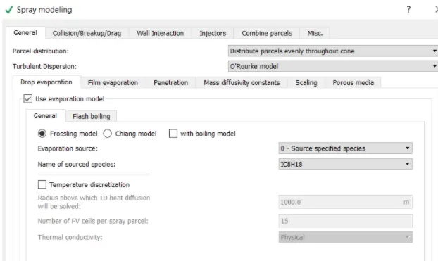
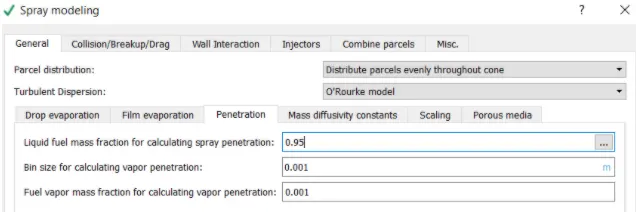
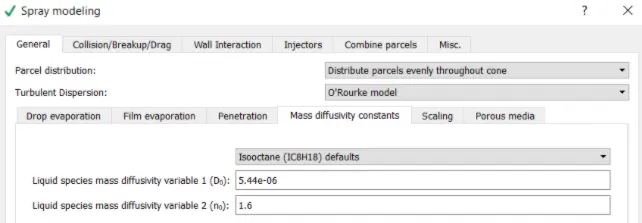
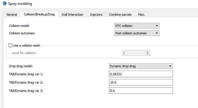
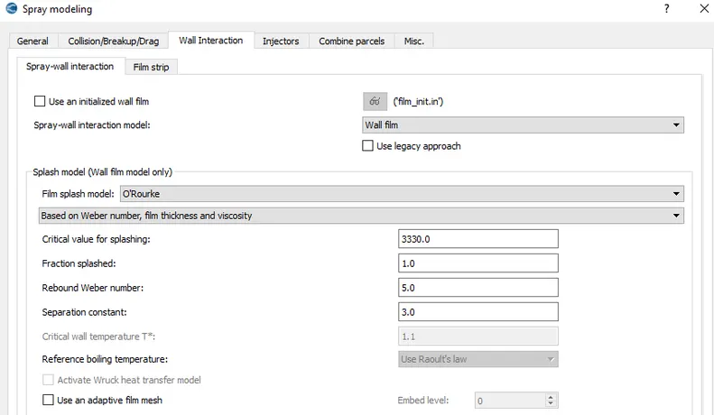
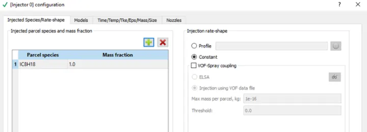
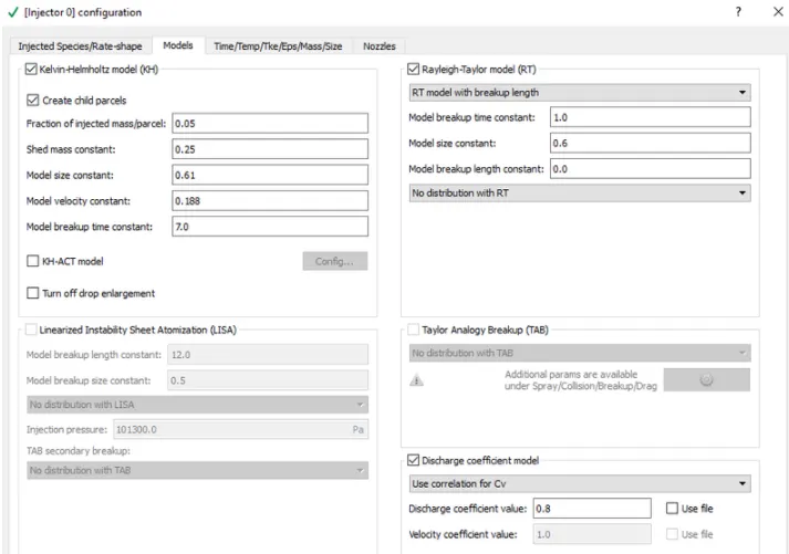
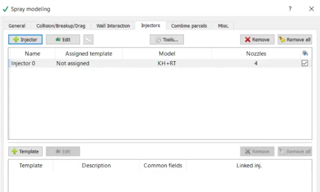
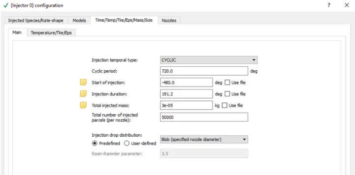
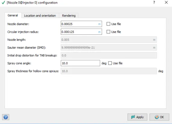
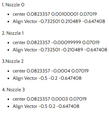
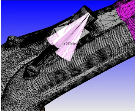
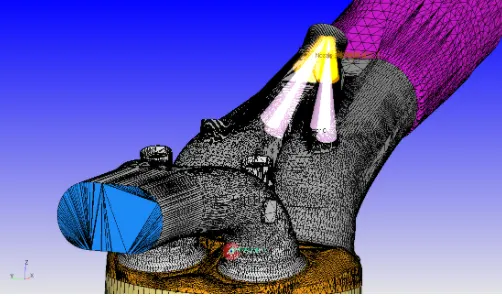
After creating the nozzle, those can be seen in the engine geometry.
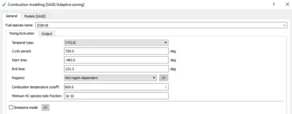
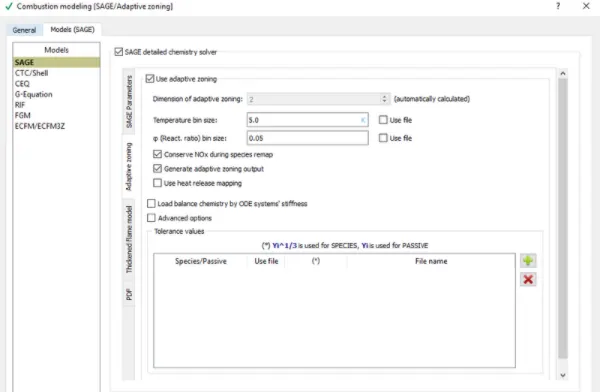
Combustion modelling:
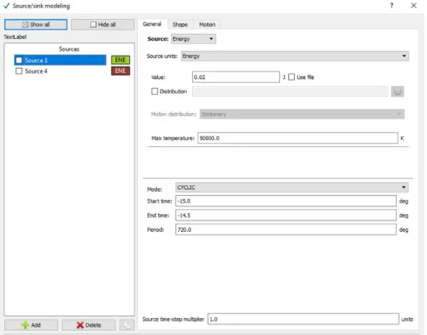
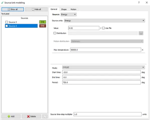
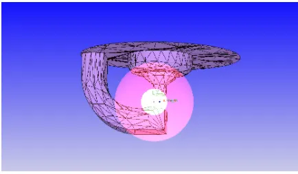
Source and Sink modelling:
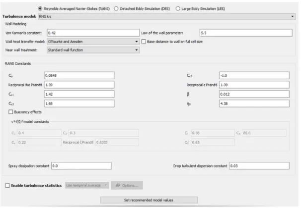
Turbulence Modelling: RNG k-E
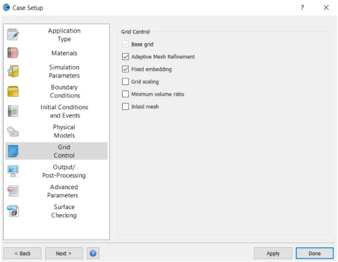
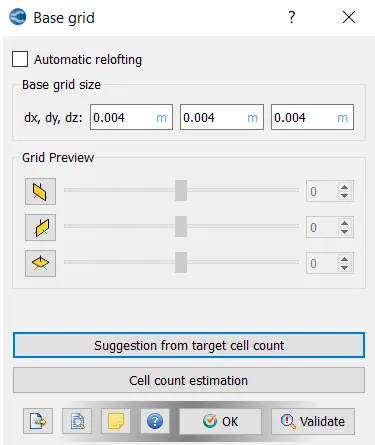
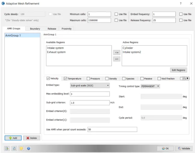
Grid Control:
Adaptive mesh timing map:
Fixed Embedding:
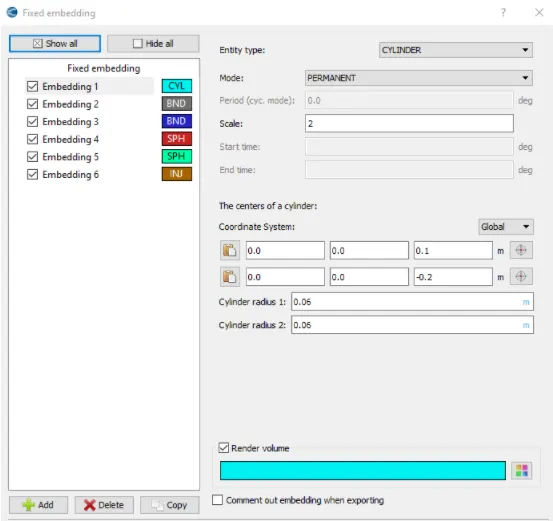
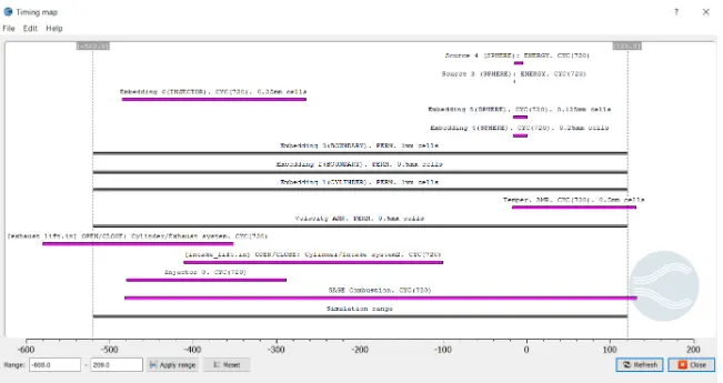
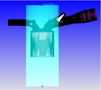
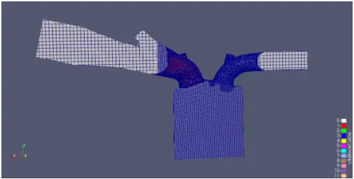
Cylinder embedding is applied such that it covers the cylinder region and a part of intake and exhaust region.
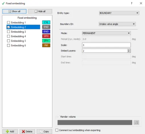
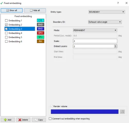
Boundary embedding is applied on intake valve angle and exhaust valve angle with a embedd scale of 3 and 2 respectively.
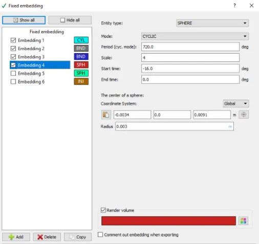
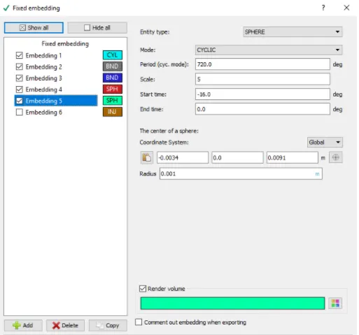
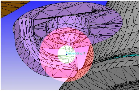
Spherical embedding were applied at the spark plug electrode with a embed scale of 4 and start time of -16 degree and end time is 0 degree, start and end time needs to be specified since cyclic mode is selected.
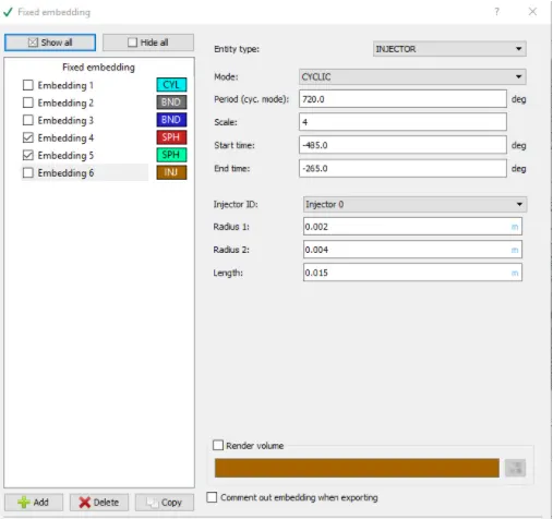
Injector embedding is applied on the injector. A cyclic embed is set with a period of 720 degree with start time of -485 degree and end time of -265 degree and with a scale of 4.
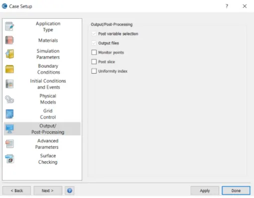
Output and Post-processing:
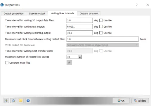
Results:
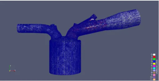
Meshing:
Plots:
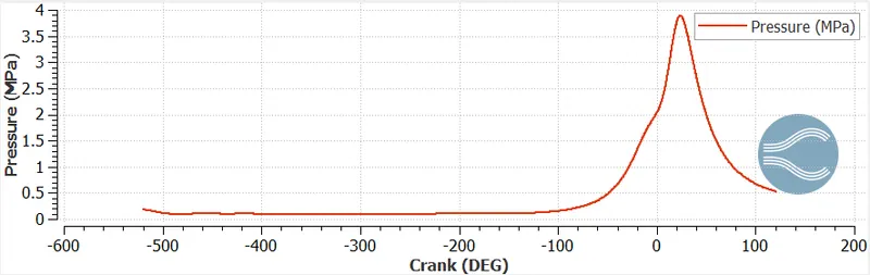
Pressure plot:
The maximum valve of the pressure in compression stroke is 3.8MPa.
In the expansion stroke it is observed that pressure decreases rapidly.
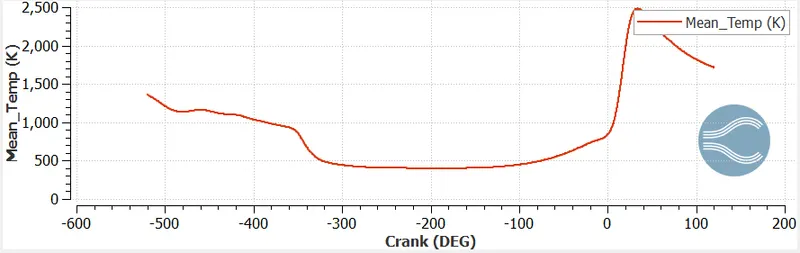
Mean temperature plot:
In SI Engine, Spark ignites the compressed air-fuel mixture and the flame propagates in the complete system.
The mean temperature in the compression stage reaches the maximum valve of 2500K
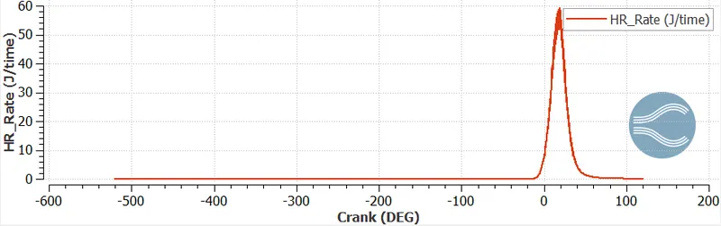
Heat release rate:
This plot indicates the heat released through the period of cycle. Heat release is increased once the combustion starts and decreases in the end of the cycle.
Volume Plot:
Ratio of Maximum volume to the minimum volume indicates the compression ratio of the cylinder.
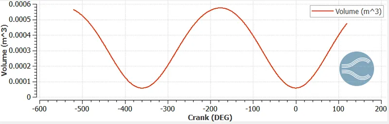
Compression ratio = (maximum cylinder volume) /(minimum cylinder volume)
Min cylinder volume = 5.70311e-05 at 360 degree crank
Max cylinder volume = 0.00057 at 176 deg crank
Compression ratio = 0.00057/5.70311e-05
= 9.994
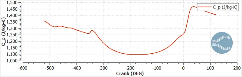
Cp plot:
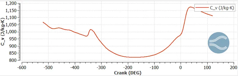
Cv plot:
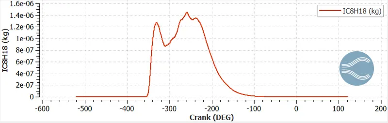
IC8H18 plot:
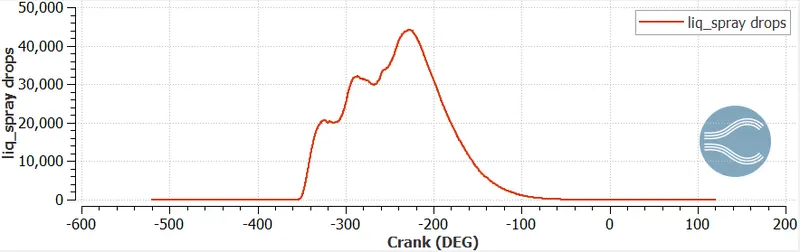
Liquid spray droplets:
Emissions:
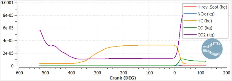
The above plot shows the behaviour of emissions. In order to control the emissions use the after treatment systems in the exhaust system also follow the Bharat stage emission regulations.
Why do we need a wall heat transfer model? Why can't we predict the wall temperature from the CFD SIMULATION?
To perform good and accurate prediction of engine heat transfer, wall temperature models are used for accomplishing heat transfer from the hot gases to all the engine parts.
In IC Engine during power stroke, the air-fuel mixture gets ignited by the spark plug and hence chemical reactions takes place in the chamber. These reactions raise the temperature inside the chamber and hence forces in the piston to expand.
Important correlation are reviewed for three engine heat transfer approaches i.e. gas to wall, wall to wall, wall to liquid Heat transfer models.
To get the good prediction of wall temperature, all this approaches must be coupled. Heat transfer is the passage of thermal energy from hot to cold region. This passage occurs in 3 different modes i.e. Conduction, Convection and Radiation.
Conduction is the diffusion process; here heat is transferred by the direct contact. Convection is associated to fluid motion. In natural convection the fluid motion is generated by the heat transfer, the fluid close to the hot surface becomes lighter and rises. Whereas in forced convection the fluid motion is driven by external. Radiation depends on the wave propagation process; here heat is transferred by means of electromagnetic waves.
PFI Engine simulation takes a lot of time to compute the case as it contains complex geometry. If we want to capture the heat transfer we need to solve energy equations should be solved to get convection of heat from fluid to solid surface. Hence this increases the computational time. For simulating the complex geometry it needs lot of time for computing the fluid part itself in transient case along with the combustion process. Thus it is becomes to difficult to predict the wall temperature for CFD simulations solving of heat transfer along with Navies Stokes equations which take more run time.
Wall heat transfer models are used if we are focused only on the heat transfer by giving less preference to fluid motions and the reactions. To maintain the good efficient operation proper cooling is provided at the walls.
Combustion Efficiency of the engine:
The basic definition of combustion efficiency is amount to fuel burned that can be utilized into work.
100% of efficiency is not possible, because having some losses.
Mass of fuel injected = 3e-05 kg
Total heat release = 1241 J
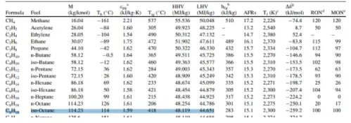
Lower calorific value = 44 MJ/K
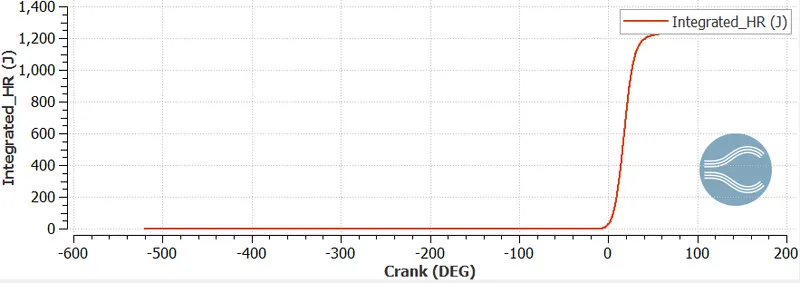
Combustion efficiency = (total heat released)/ (Total energy content of fuel)
= (total heat released)/(mass* lower calorific value)
= 1241/(3e-05*44)
= 94.2%
Use the engine performance calculator, to determine the power and torque for this engine.

From above calculated result from calculator:
Gross work = 468.646 (N*m)
Time duration = 240.199 deg
Converting deg into sec
RPM = 3000
RPS = 3000/60 = 50
Single rotation of piston = 360 deg
Rotation per second = 50*360 = 18000 deg/sec
Time for combustion = Time Duration/Rotation per sec
= 240.199/18000
= 0.0133 sec
Power = work/time
= 468.646/0.0133
= 35236.54 W
= 35.23 KW
Power(P) = (2*π*N*T)/60
T = 60*P/(2*π*N)
= 60*35236.54/ (2*π*3000)
= 112.2 N-m
Torque T = 112.2 N-m
Significance of ca10, ca50 and ca90:
ca10, ca50, ca90 are defined as the position of crank angle in degree at which the cumulative heat release reaches at 10%, 50%, 90% respectively.
ca10 represents start of ignition
ca50 represents end of air-fuel combustion
ca 90 represents end of combustion.
Animation link:
Meshing on Full Hydro Setup:
Flame propagation in Full Hydro setup:
Velocity Animation:
Conclusions:
Initially did the Surface preparation and boundary flagging for remove the errors in the case setup (Full Hydro).
Different plots are created to understand the parameters in the engine.
Calculated the combustion efficiency, Compression ratio, Power and torque in the engine using parameters and performance calculator.
Also significance of ca10,ca50,ca90 studied.