Transient simulation of flow over throttle body
Aim: To Study the Transient state simulation of flow over throttle body.
Software used: Converge CFD
Theory:
The throttle valve used in IC Engines, it is a circular disc placed near to the intake manifold which controls the mass flow rate of air fuel mixture entering the combustion chamber.
In a petrol engine, the throttle valve impacts the quantity of air that is drawn in. More or less fresh air or air-fuel mixture flows into the cylinder according to how open the valve is. The position of the throttle valve directly determines the performance of the engine.
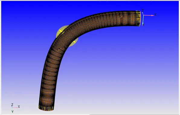
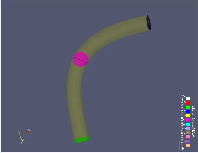
Geometry in Converge CFD:
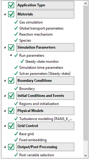
Case Setup:
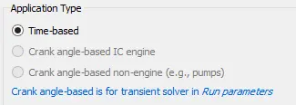
Application type:
Materials : Air
Simulation Parameters:
Run Parameters:
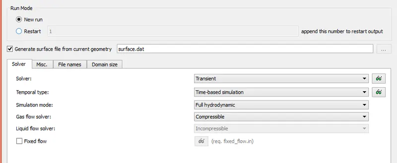
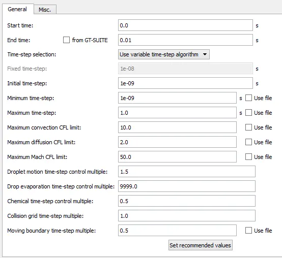
Simulation time parameters:
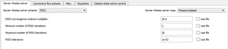
Solver Parameters:
Boundary Conditions:
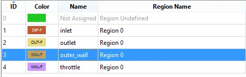
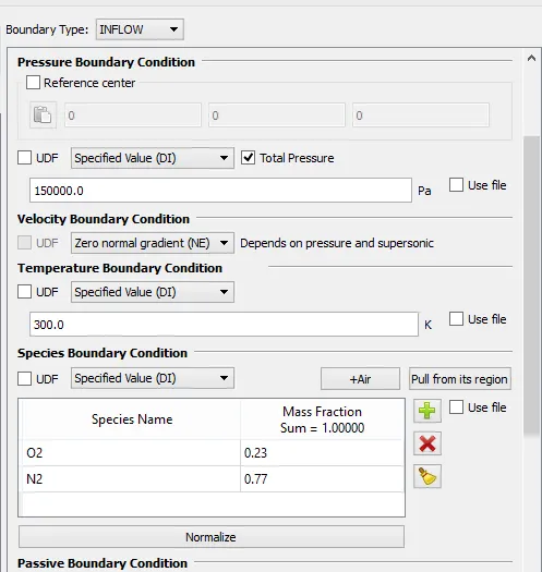
Inlet:
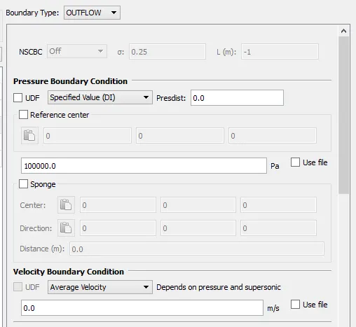
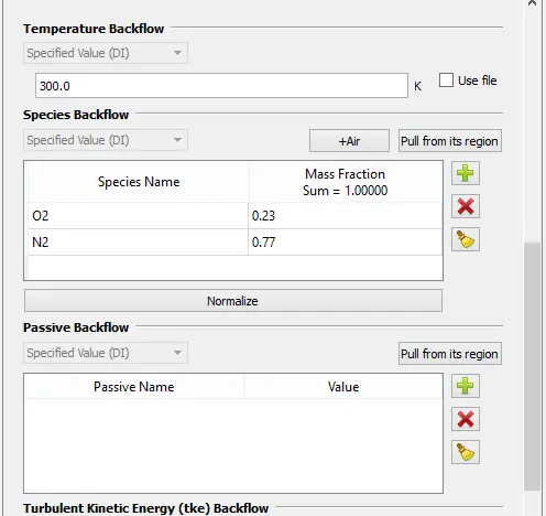
Outlet:
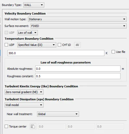
Outerwall:
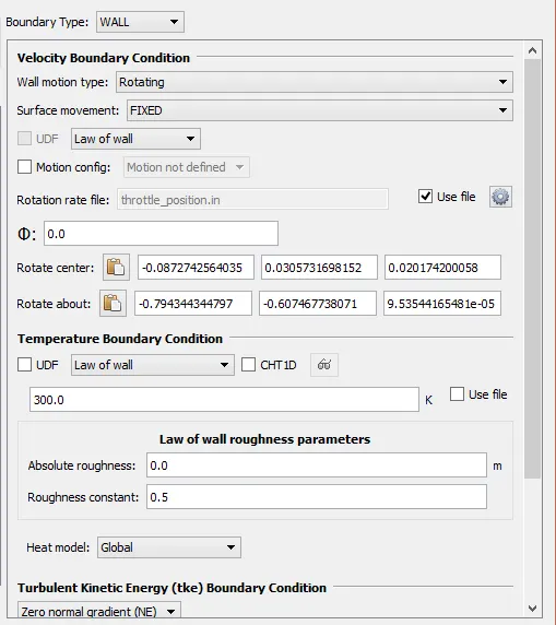
Throttle wall:
Intial conditions:
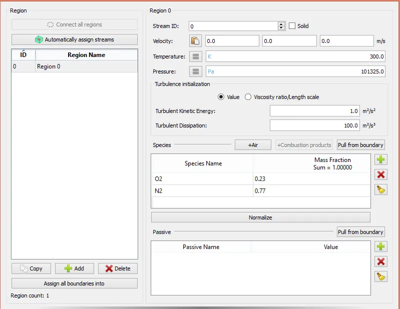
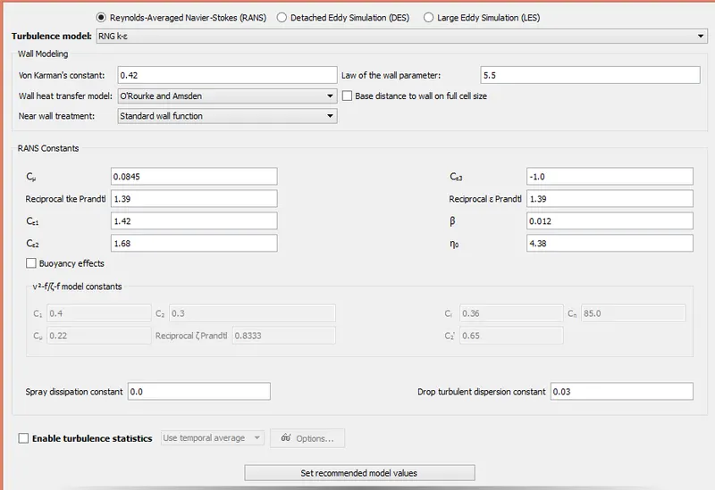
Physical Models:
Turbulence model- RANS
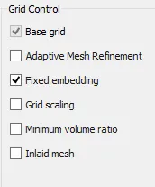
Grid Control:
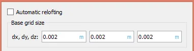
Base Grid:
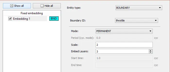
Fixed embedding:
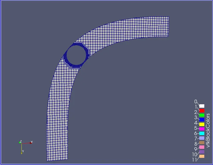
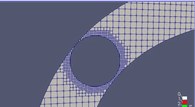
Mesh:
Contours:
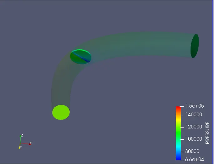
Pressure:
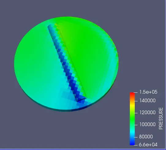
Pressure at Throttle:
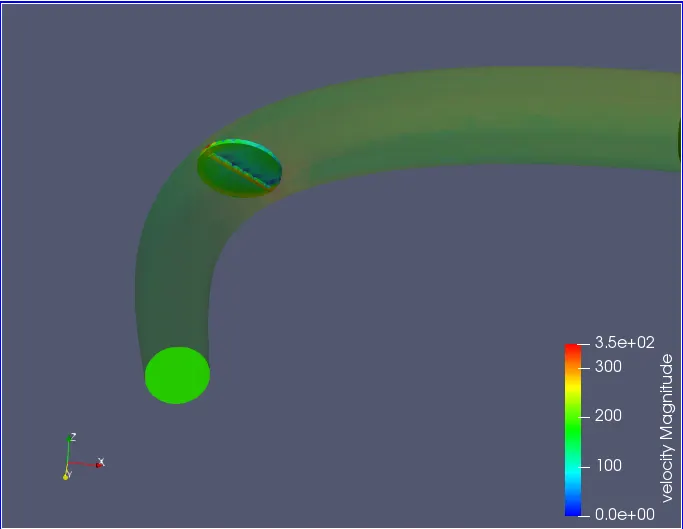
Velocity:
Velocity vectors:
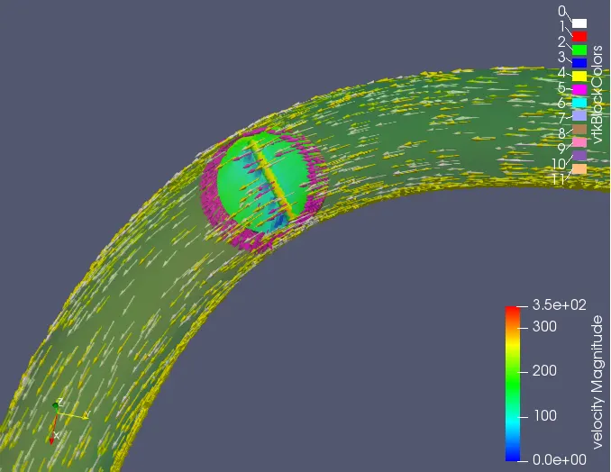
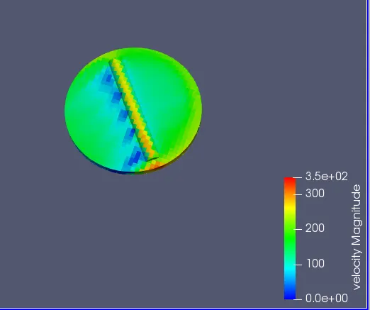
Velocity at throttle:
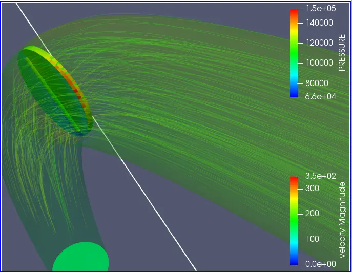
Steam Lines:
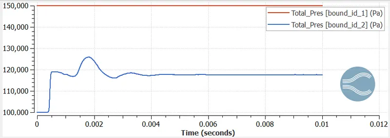
Plots:
Pressure:
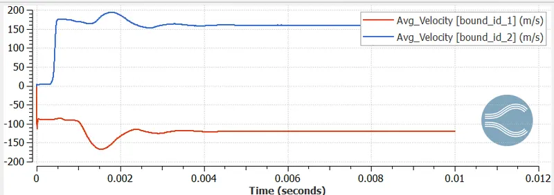
Velocity:
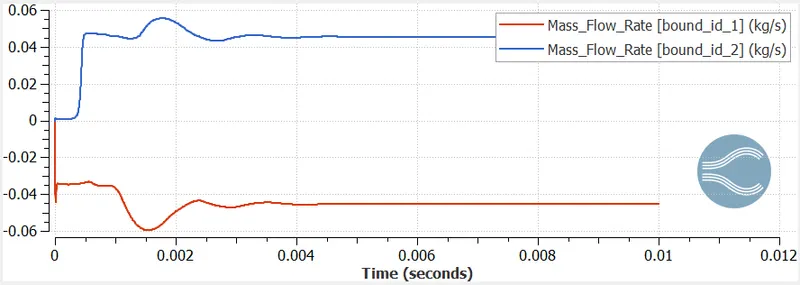
Mass Flow Rate:
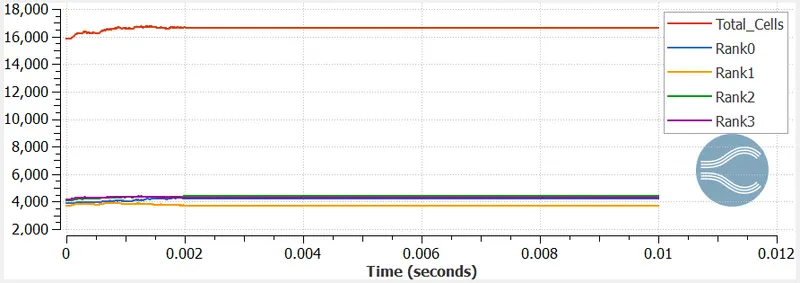
Total cell Count:
Also show the calculations on how you calculated an end time for the simulation.
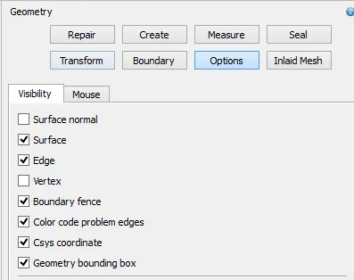
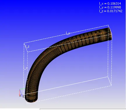
First calculate the total length along the pipein meters, for calculating the length along the pipe use bounding box option in geometry.
Next calculate the average velocity in (m/s).
End time = length/velocity
= m/(m/s)
= sec
Then yo will get the estimated end time of the simulation.
Observations:
Fixed embedding helps to refine the mesh around the boundary of throttle plate.
Front side of the throttle plate having higher pressure because air strike on the plate.
Velocity is decrease on front side of the throttle plate but after that velocity increase because decrease in total pressure.
The inlet and outlet mass flow rate stabilise over time,as shown in the graph.