Flow Over a Backward facing step using Converge CFD
Aim:To Simulate the Flow over a backward facing step using Converge CFD with diffrent mesh grid sizes.
Software Used: Converge CFD
Objective:
1. Run the simulation for diffrent Mesh sizes
2. Contour plots of diffrent parameters
3. post process the results in Paraview and Converge post
Theory:
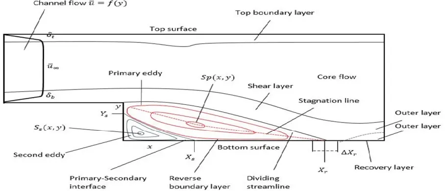
Backward-Facing Step (BFS) flow is one representative model for separation flows, which can be widely seen in aerodynamic flows (airfoil, spoiler, high attack angle process), engine flows, condensers, vehicles (cars, boat), heat transfer systems, and even the flow around buildings, etc. The flow separation after a simple stage will introduce separation bubble formation, evolution and re-attachment process, which is dependent on the BFS geometric design, the inlet and outlet conditions, turbulent intensity, as well as heat transfer conditions.
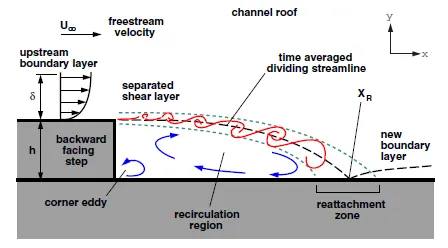
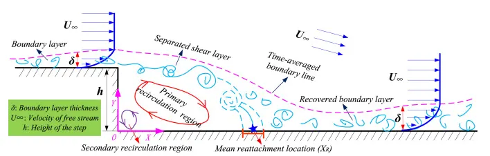
Fully developed flow enters the domain from left, when the flow reaches the step, because of expansion of flow channel, pressure gradient exits, it detaaces and a recirculation zone is formed. A turbulent boundary layer encounters a sudden back step, causing flow separation. Later the flow eventually reattaches to the bottom.
Importance of backward facing problem stepping:

Fixed Embedding:

Geometry Creation:

Case setup:
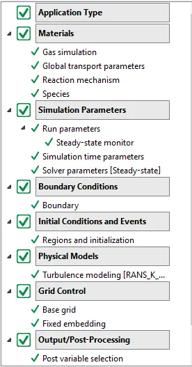
1. Application type: Time based-steady state
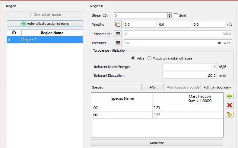
2.Materials : Air
Species : N2 and O2
3.Simulation Parameters:
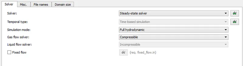
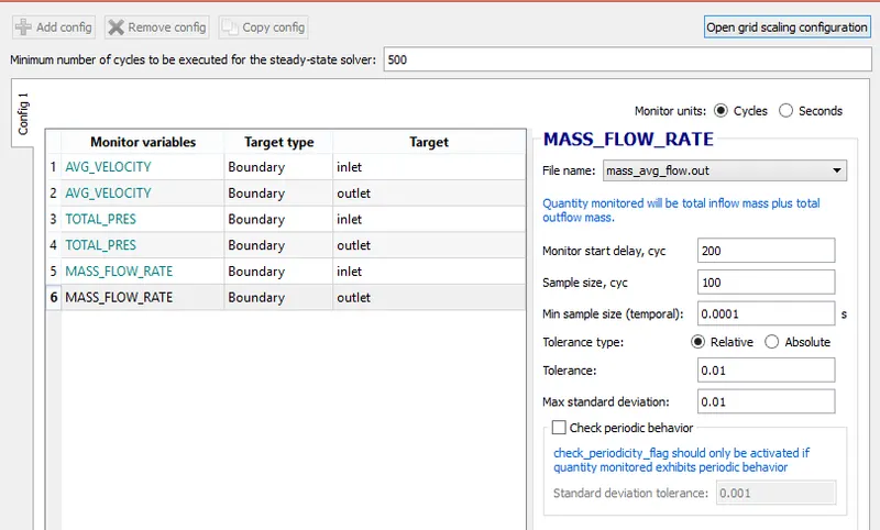
Steady-state monitor:
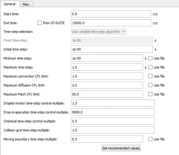
Simulation time parameters:
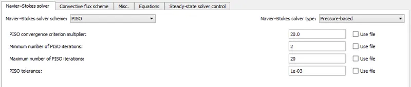
Solver parameters:
Boundary Conditions:
1.Inlet flow
Pressure=110325 pa Temperature = 300k
2. Outlet flow
Pressure=101325 pa Temperature = 300k
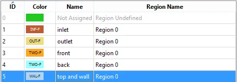
Regions and intializations
Physical models:
Turbulence model: RANS
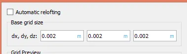
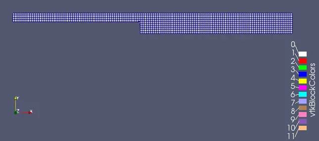
Mesh 1:
dx = dy = dz =2e-3m
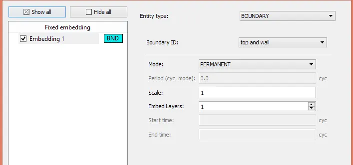
Fixed embedding:
Plots:
Meshing:
Contours:
Velocity:
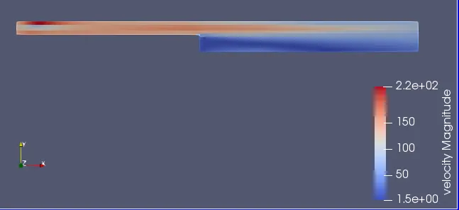
The above velocity contour represents the flow in backward step. the velocity is higher at inlet with a 220m/s and at the outlet of the velocity is gradually decline with a 50 m/s due to increased in geometry and at the step the velocity is very low due to divergent nozze and flow is turbulent so the pressure droping takes place so velocity starts decreasing.
Pressure:
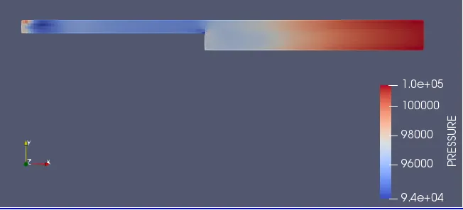
Initially the preesure is high at the inlet and it goes on increasing untill it reaches the seperation point.
vectors:
Velocity:
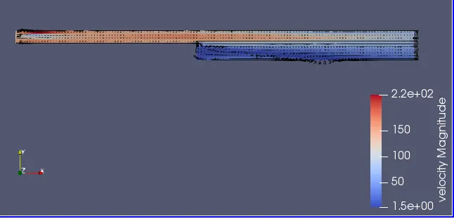
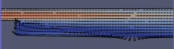
In the velocity vector contour the velocity ater the step is recirculating because of the seperation in the flow and form the boundary layer.
Plots:
Velocity
Pressure:
Mass Flow rate:
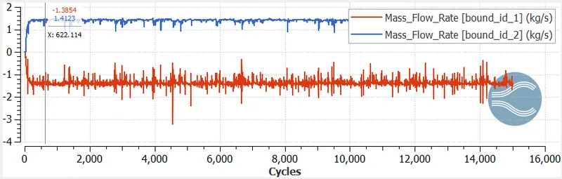
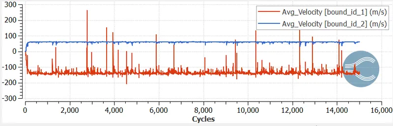
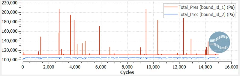
Mass flow rate is same for both inlet and outlet but they are mirror image. The solution ge convergence at mass flow rate is 1.5 kg/sec.
Total cell count:
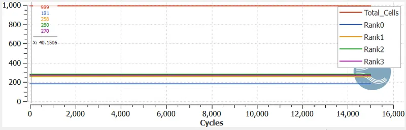
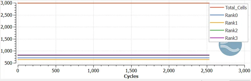
The total no of cells is 1000, increase the no of cells, output graph should be smooth.
Mesh 2:
dx = dy = dz =1.5e-3m
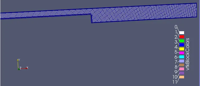
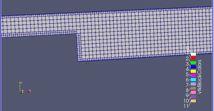
Contours:
Velocity:
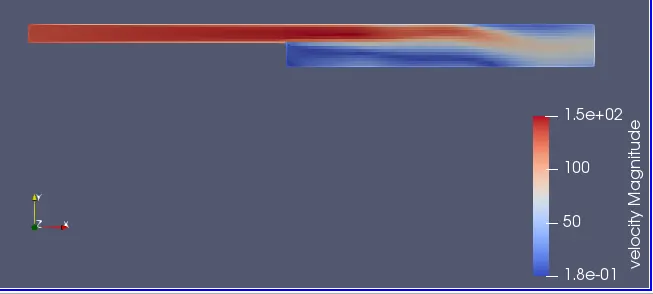
The above velocity contour represents the flow in backward step. the velocity is higher at inlet with a 150m/s and at the outlet of the velocity is gradually decline with a 50 m/s due to increased in geometry and at the step the velocity is very low due to divergent nozze and flow is turbulent so the pressure droping takes place so velocity starts decreasing.
Pressure:
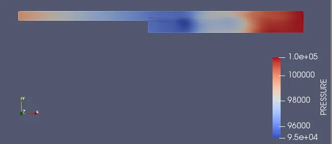
Initially the preesure is high at the inlet and it goes on increasing untill it reaches the seperation point.
Vectors:
Velocity
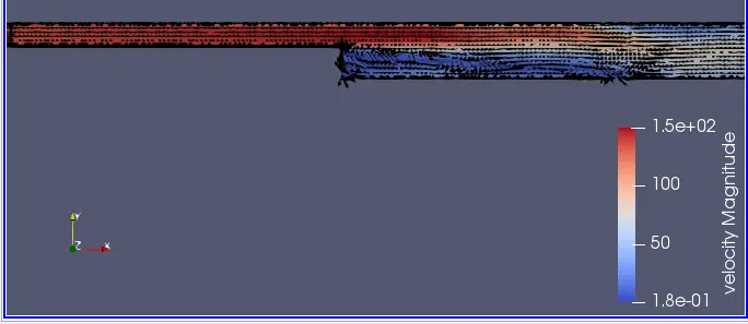
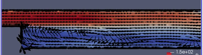
In the velocity vector contour the velocity ater the step is recirculating because of the seperation in the flow and form the boundary layer.
Plots:
Velocity
Pressure
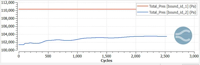
Mass Flow rate:
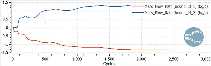
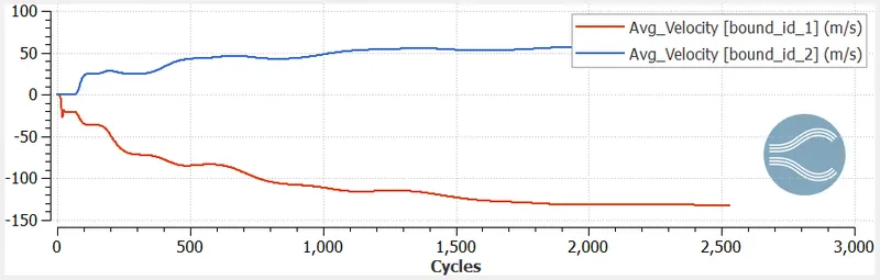
Mass flow rate is same for both inlet and outlet but they are mirror image. The solution ge convergence at mass flow rate is 1.5 kg/sec.
Total cell Count:
Mesh 3:
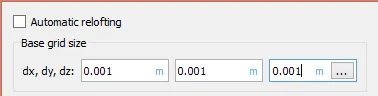
dx = dy = dz =1.0e-3m
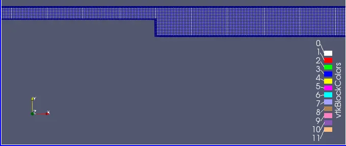
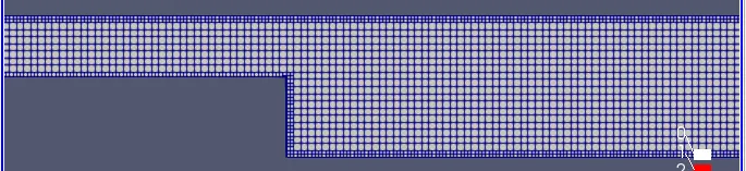
Meshing:
Contours:
Velocity
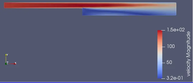
The above velocity contour represents the flow in backward step. the velocity is higher at inlet with a 150m/s and at the outlet of the velocity is gradually decline with a 50 m/s due to increased in geometry and at the step the velocity is very low due to divergent nozze and flow is turbulent so the pressure droping takes place so velocity starts decreasing.
Pressure:
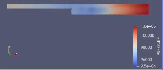
Initially the preesure is high at the inlet and it goes on increasing untill it reaches the seperation point.
Vectors:
Velocity:
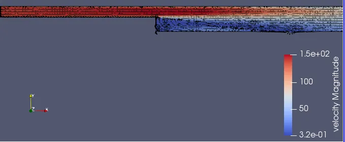
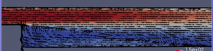
In the velocity vector contour the velocity ater the step is recirculating because of the seperation in the flow and form the boundary layer.
Plots:
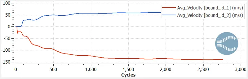
Velocity:
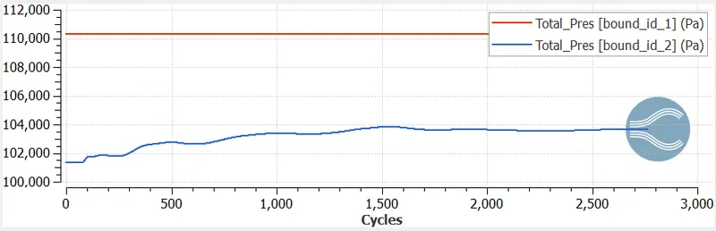
Pressure:
Mass flow rate:
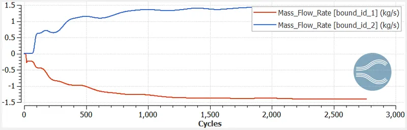
Mass flow rate is same for both inlet and outlet but they are mirror image. The solution ge convergence at mass flow rate is 1.5 kg/sec.
Total cell count:
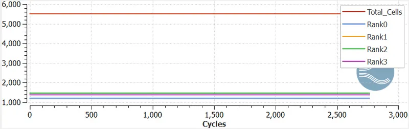
Seperation Region:
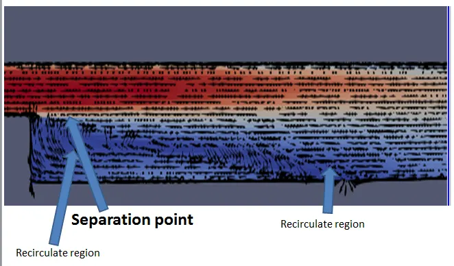
From the above images we can observed the general characteristics off the flow begins were the upstream boundary layer develops and the pressure gradient is developed.
The primary vertex is accured at the center rom the step and the secondary vertex is formed at the corner of the step. The pressure gradient roms the shear layer goes down the wall and touches the wall.
Some of the streams flow right and forms the recirculatin region and some goes right and reaches the outlet.
Increase the mesh refinement, velocity profile forms smoothly.