Gate Valve Parametric Study
Aim: Perform a parametric study of the gate valve simulation for opening rom 10% to 80%
Software Used: Ansys Fluent
Theory:
Gate Valve:
A gate valve controls the media's flow by lifting the gate (open) and lowering the gate (closed). A gate valve's distinct feature is the straight-through unobstructed passageway, which induces minimal pressure loss over the valve. The unobstructed bore of a gate valve also allows for a pig's passage in cleaning pipe procedures, unlike butterfly valves. Gate valves are available in many options, including various sizes, materials, temperature and pressure ratings, and gate and bonnet designs.
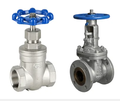
Gate valves tend to be slightly cheaper than ball valves of the same size and quality. They are slower in actuation than quarter-turn valves and are for applications where valve operation is infrequent, such as isolating valves. Gate valves should be used either fully open or fully closed, not to regulate flow. Automated gate valves exist with either an electric or pneumatic actuator, but a manual gate valve is cost-effective since they have infrequent usage.
Parametric study: A parametric analysis or sensitivity analysis is the study of the influence of different geometric or physical parameters or both on the solution of the problem.
As you move forward in your design, you can assess the impact that changing certain parameters can have on the design. The parameters can include dimensional parameters. Parametric studies allow you to nominate parameters for evaluation, define the parameter range, specify the design constraints, and analyze the results of each parameter variation.
A parametric study requires the following:
- Design Objective is set to Parametric Dimensions
- Parameters nominated for use in the simulation
- Parameter ranges identified
- Design criteria specified
- Various configurations generated
When you have the configurations generated you can then evaluate your simulation. You can further refine the parameters or design constraints until satisfied with the results.
Once you determine that a configuration satisfies your design needs, you are able to promote that configuration back to the model as a CAD edit. You are prompted whether to make changes.
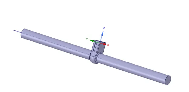
Geometry:
First import the step file in space claim.
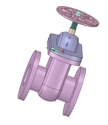
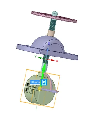
Next click the move option in the space claim for changing the translational position of the gate disc. Also perform the parametric study on the gate disc.
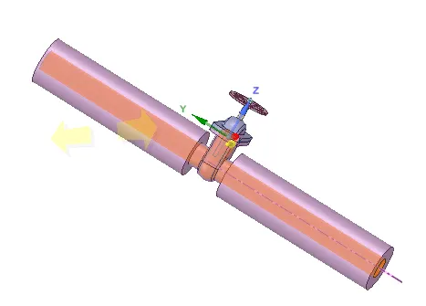
Create the volumetric region at the openings.
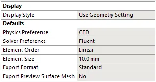
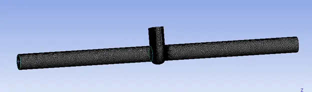
Meshing:
Mesh for the fluid volume of the gate value.

Case setup:
Solver: Pressure based,
Analysis: Steady state simulation
Gravity -9.81m/s2 in z direction.
Models:
K-Epsilon, Realizable model, Scable wall functions
Materials: Water-liquid (H2O)
Density: 998.2 kg/m3
Viscosity: 0.001003 kg/(m-s)
Boundary Conditions:
Inlet: Pressure inlet, gauge pressure-10 pa
Outlet: Pressure outlet, Gauge pressure-0 pa
Initialization:
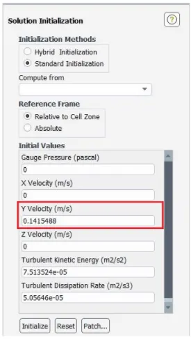
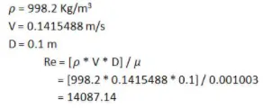
Reynolds number is 14087.14, so flow is turbulent.
So viscous model will be K-Epsilon.
Flow Coefficient:
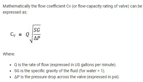
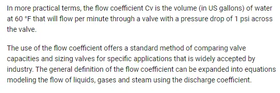
The flow coefficient of a device is a relative measure of its efficiency at allowing fluid flow. it describes the relationship between the pressure drop across an orifice valve or other assembly and the corresponding flow rate.
Flow Factor:
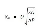
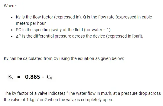
The metric equivalent flow factor is calculated using metric units:
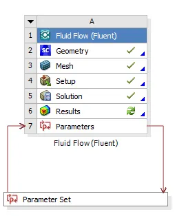
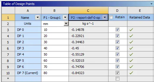
Parametric Study:
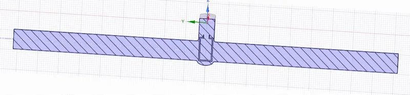
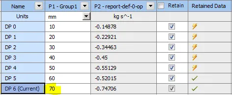
Case 1: lift 10 mm

Geometry:
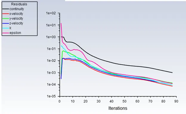
Residual Plot:
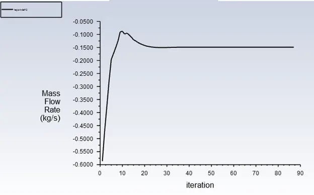
Mass Flow Rate:
Contours:
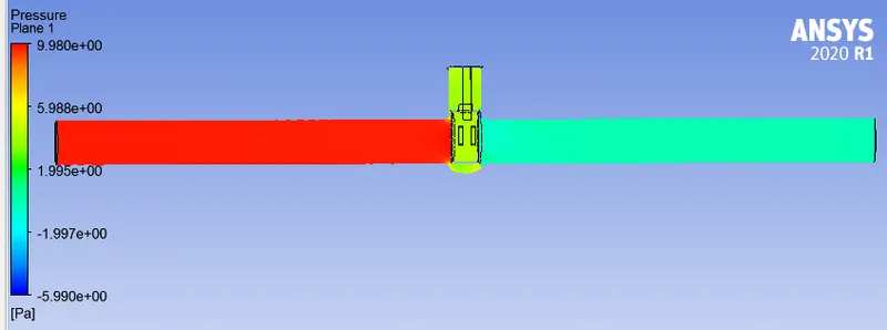
Pressure:
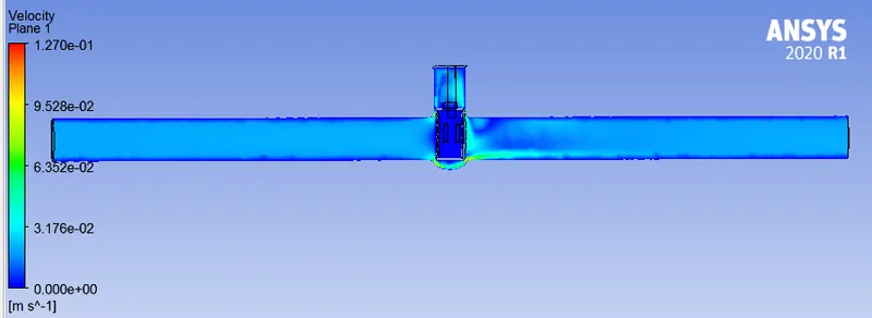
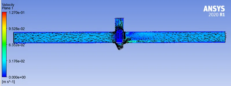
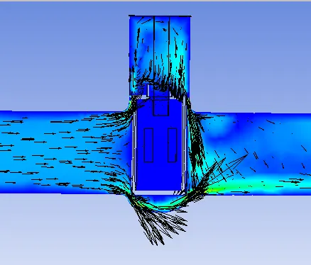
Velocity:
Vectors:
Flow Coefficient:
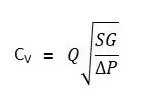
Q = 0.14878
SG = 1000/998.2 = 1
pressure difference = 10
= 0.14878* 
=0.14878*0.31622
Cv = 0.04704
Flow Factor:
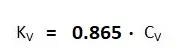
= 0.865* 0.04704
= 0.04069
Case 2: lift 20 mm

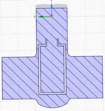
Geometry:
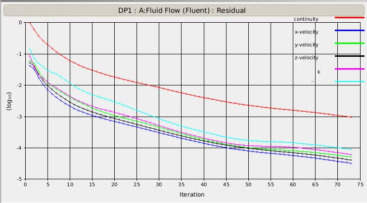
Residual Plots:
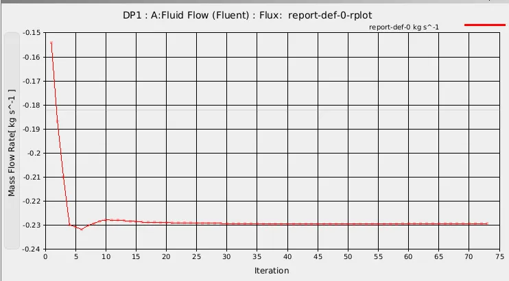
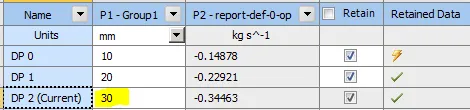
Mass flow rate:
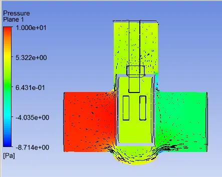
Contours:
Pressure:
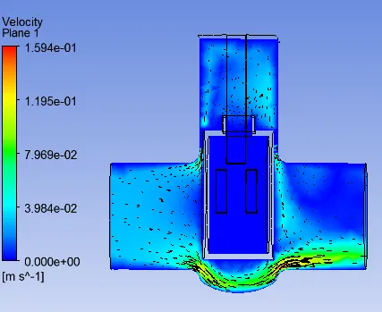
Velocity:
Flow Coefficient:
Q = 0.22921
SG = 1000/998.2 = 1
pressure difference = 10
= 0.22921*
=0.22921*0.31622
Cv = 0.07248
Flow Factor:
= 0.865* 0.07248
= 0.06269
Case 3: lift 30 mm
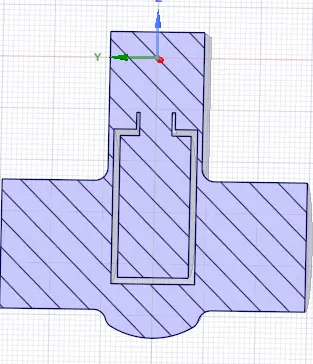
Geometry:
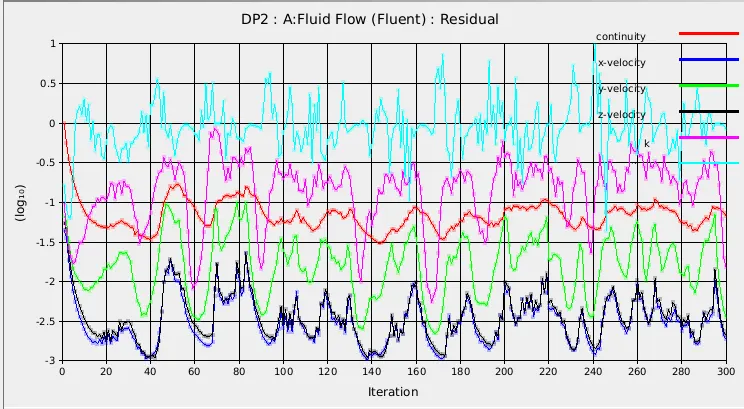
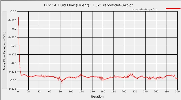
Residual Plots:
Mass flow rate:
Contours:
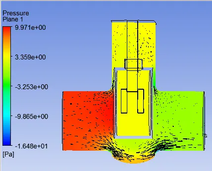
Pressure:
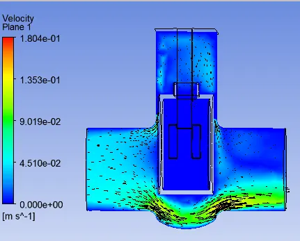
Velocity:
Flow Coefficient:
Q = 0.34463
SG = 1000/998.2 = 1
pressure difference = 10
= 0.34463*
=0.34463*0.31622
Cv = 0.10897
Flow Factor:
= 0.865* 0.10897
= 0.09426
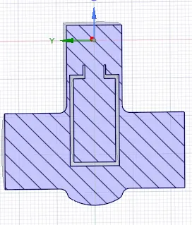
Case 4: lift 40 mm
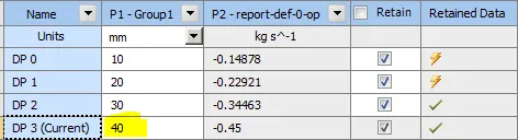
Geometry:
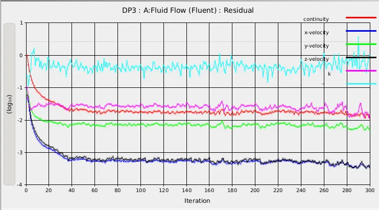
Residual Plots:
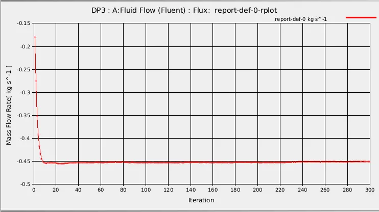
Mass flow rate:
Contours:
Pressure:
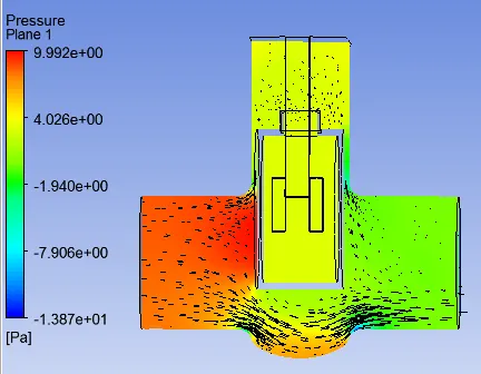
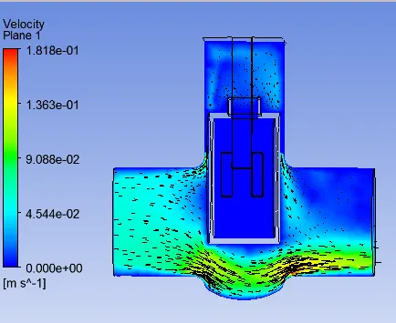
Velocity:
Flow Coefficient:
Q = 0.45
SG = 1000/998.2 = 1
pressure diffrence = 10
= 0.45*
=0.45*0.31622
Cv = 0.1422
Flow Factor:
= 0.865* 0.1422
= 0.1230
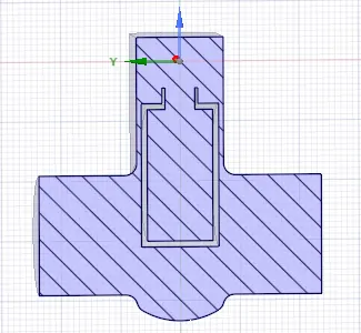
Case 5: lift 50 mm
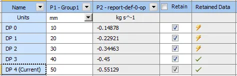
Geometry:
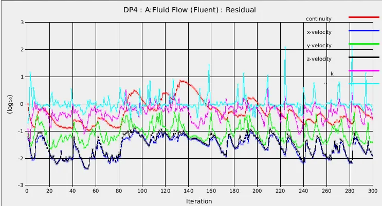
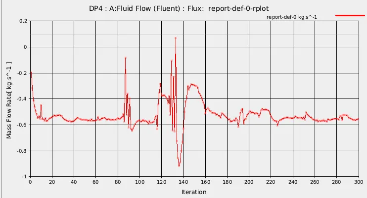
Residual Plots:
Mass Flow rate:
Contours:
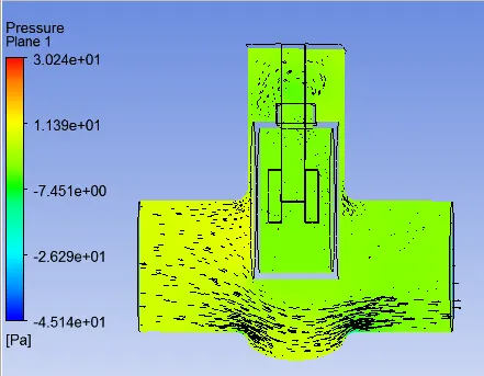
Pressure :
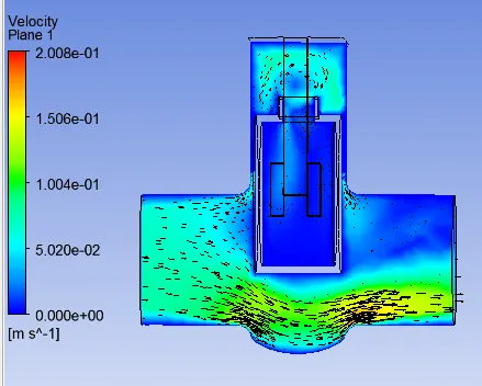
Velocity:
Flow Coefficient:
Q = 0.55129
SG = 1000/998.2 = 1
pressure difference = 10
= 0.55129*
=0.55129*0.31622
Cv = 0.17432
Flow Factor:
= 0.865* 0.17432
= 0.15079
Case 6: lift 60 mm
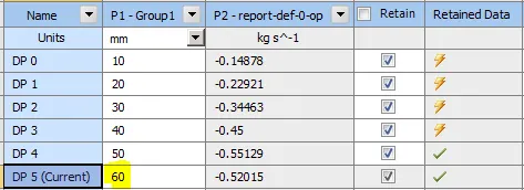
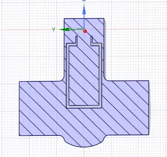
Geometry:
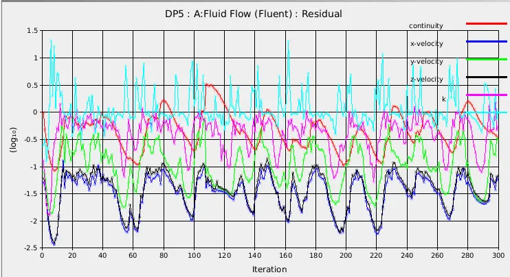
Residual Plots:
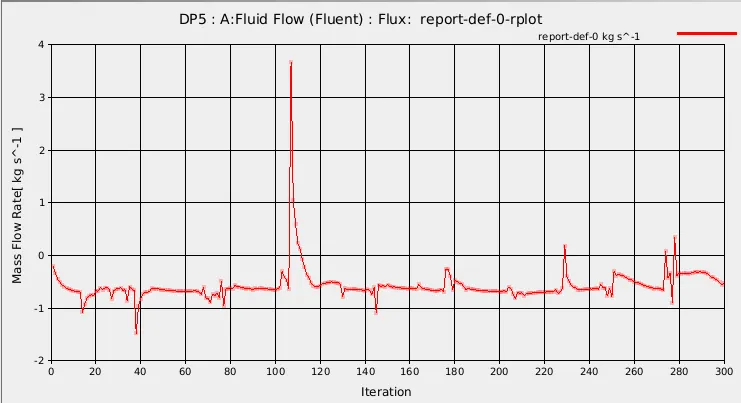
Mass flow rate:
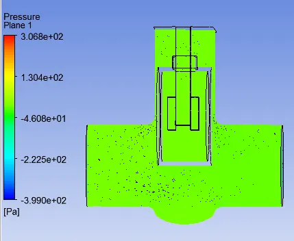
Contours:
Pressure:
Velocity:

Flow Coefficient:
Q = 0.5201
SG = 1000/998.2 = 1
pressure difference = 10
= 0.5201*
=0.5201*0.31622
Cv = 0.16446
Flow Factor:
= 0.865* 0.1644
= 0.14226
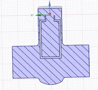
Case 7: lift 70 mm
Geometry:
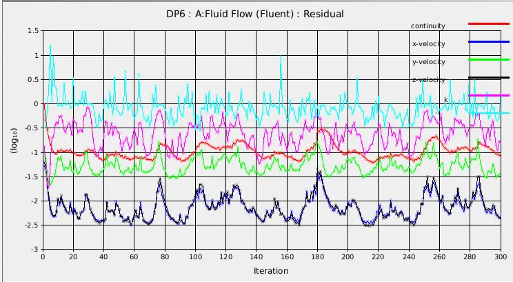
Residual Plots:
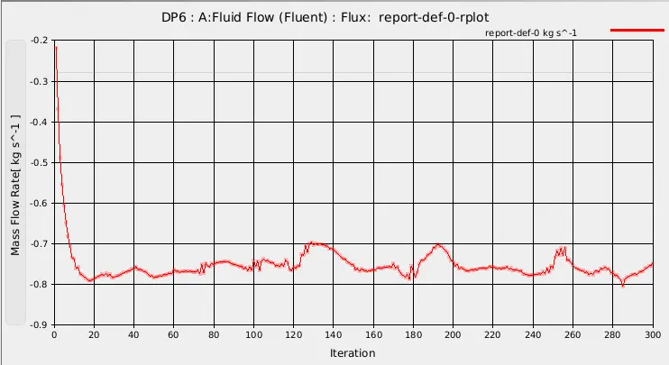
Mass flow rate:
Contours:
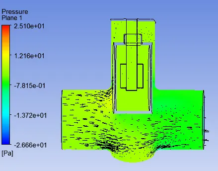
Pressure:
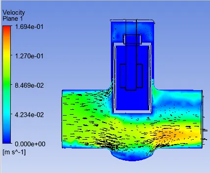
velocity:
Flow Coefficient:
Q = 0.74706
SG = 1000/998.2 = 1
pressure difference = 10
= 0.74706*
=0.74706*0.31622
Cv = 0.23623
Flow Factor:
= 0.865* 0.23623
= 0.20434
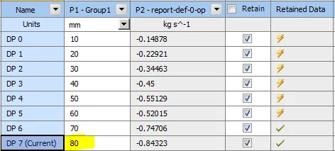
Case 8: lift 80 mm
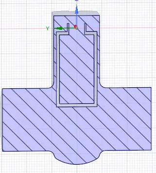
Geometry:
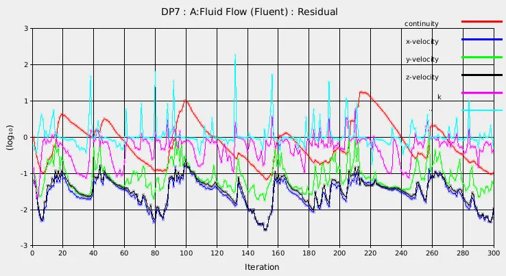
Residual Plots:
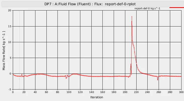
Mass flow rate:
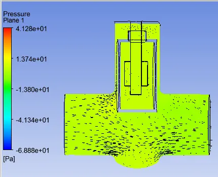
Contours:
Pressure:
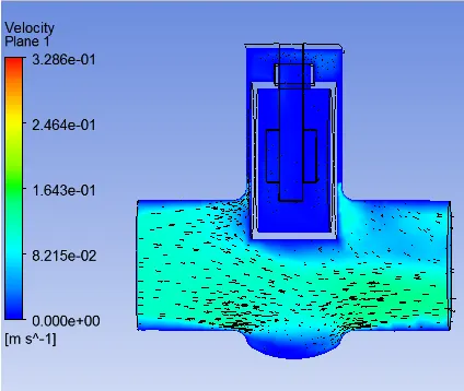
Velocity:
Flow Coefficient:
Q = 0.84323
SG = 1000/998.2 = 1
pressure difference = 10
= 0.84323*
=0.84323*0.31622
Cv = 0.26664
Flow Factor:
= 0.865* 0.26664
= 0.23064
Observations:
Graphs:
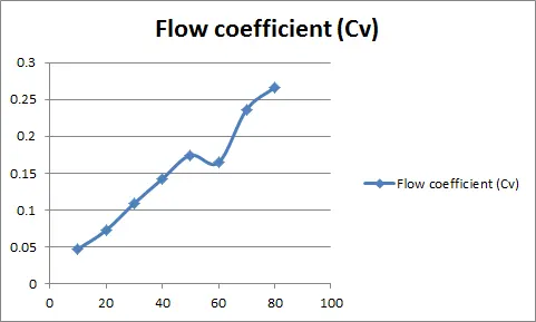
Lift vs Flow Coefficient:
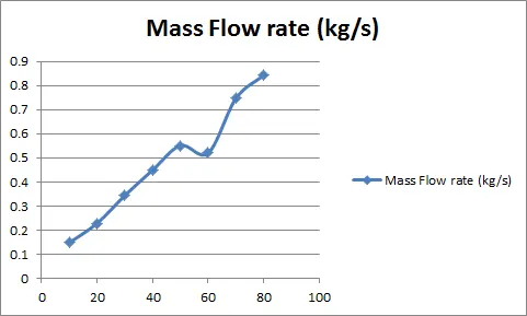
Lift vs Mass flow rate:
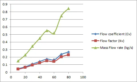
Observations:
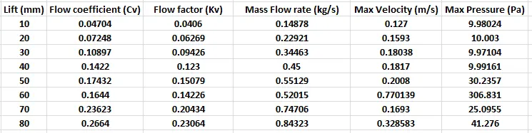
As the opening of the gate value or lift increases Mass Flow rate increases
Increases in the mass flow rate, Flow coefficient also increases
Mass Flow rate, Flow coefficient and flow factor are increasing linearly as shown in the graph.
Velocity is increasing slowly, when valve lift increases But velocity is high when value lift at 60mm.
Max Pressure also obtained at value lift is 60mm.we observed that pressure is low at the outlet.
When the valve is fully open, the mass flow rate and flow coefficient becomes maximum.
Flow coefficient plays important role in selection of valve and sizing of a valve and also calculates the effect of pressure on the system.
Parametric study helps to analyse the different positions of valve openings and gives the quick results of different variables.
A parametric study requires the following:
- Design Objective is set to Parametric Dimensions
- Parameters nominated for use in the simulation
- Parameter ranges identified
- Design criteria specified
- Various configurations generated