Week 8 - Simulation of a backward facing step in OpenFOAM
Aim: Simulation of a backward facing step in OpenFOAM
Given that:
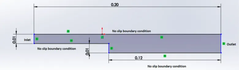
1. Simulate the flow without using any grading factor (i.e., GF = 1)
2. Simulate the flow with grading factor of 0.2. The cells should be finer near the walls (including the step wall).
Mesh specification
- Number of cells along the x direction (longer dimension) = 200
- Number of cells along the longer y direction = 20;
Theory:
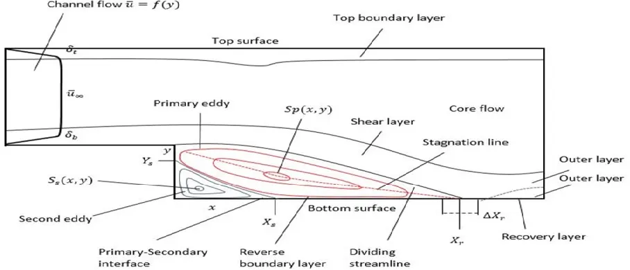
Backward-Facing Step (BFS) flow is one representative model for separation flows, which can be widely seen in aerodynamic flows (airfoil, spoiler, high attack angle process), engine flows, condensers, vehicles (cars, boat), heat transfer systems, and even the flow around buildings, etc. The flow separation after a simple stage will introduce separation bubble formation, evolution and re-attachment process, which is dependent on the BFS geometric design, the inlet and outlet conditions, turbulent intensity, as well as heat transfer conditions.
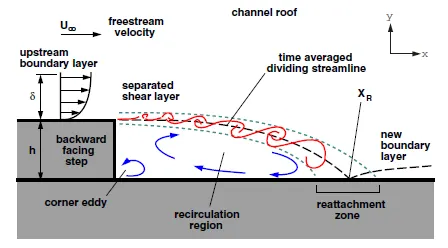
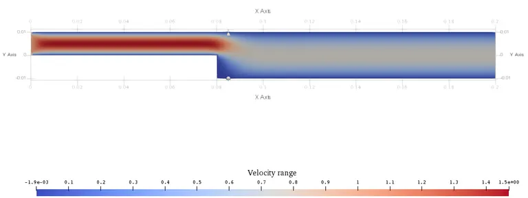
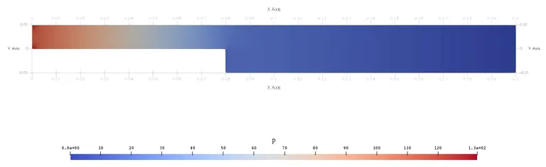
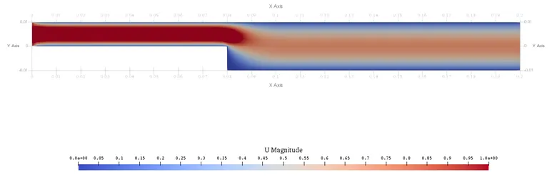
Fully developed flow enters the domain from left, when the flow reaches the step, because of expansion of flow channel, pressure gradient exits, it detaaces and a recirculation zone is formed. A turbulent boundary layer encounters a sudden back step, causing flow separation. Later the flow eventually reattaches to the bottom.
Case 1 (Grade factor =1):
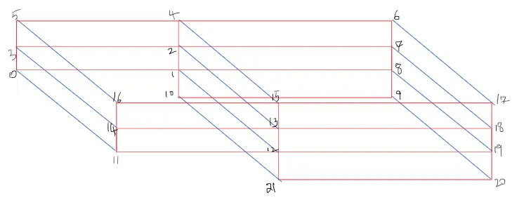
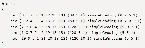
Geometry converted into 5 blocks as shown in figure:

black side:

front side:

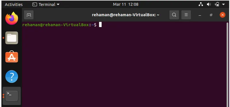
First launch the OpenFoam in Ubantu-VirtualBox, First start terminal in linux operating system using Ctrl+Alt+T. below is the terminal window.
Next, simulate our problem in Open Foam.
Solve the problem using in tutorials available in OpenFoam.
Type tut/ cd incompressible/ cd icoFoam/ cd cavity.
icoFoam is the solver in openFoam which is use as transient solver for incompressible, laminar Newtonian fluids.
In cavity, we are again going to see cavity folder where we have to define our fluid domain and generate block mesh
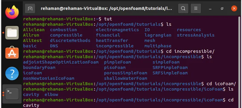

copy the cavity folder in $FOAM_RUN and then opn the run folder, where we can see the cavity_test file.

Now, we can make changes in cavity_test, here we can specify the blockmesh, intial conditions and control dict folders as per our requirement.
code for open the blockmeshdict file is:
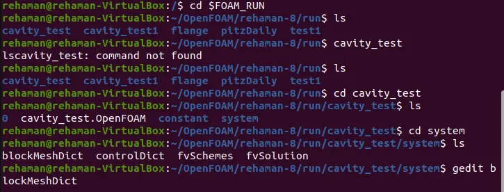
Make the changes in the blockMeshDict script file.
This file contains the information of all aspects of geometry.
blockMeshDict_file:
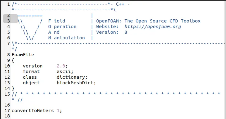
Set the units in convertToMeters.
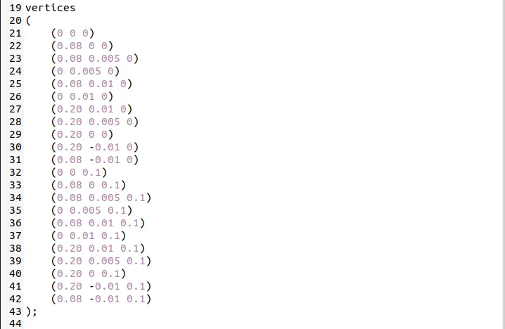
Vertices are representing the construct the geometry for the backward step problem.
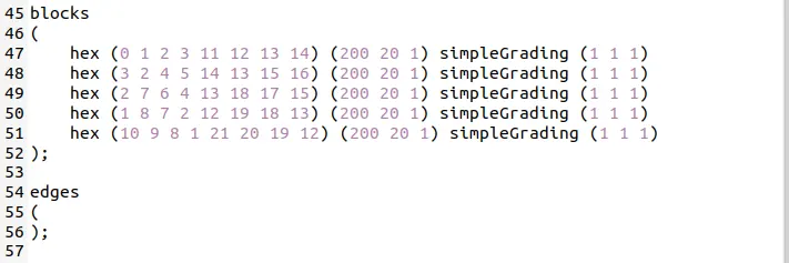
blocks represent the mesh. It specify the faces of the blocks and also the number of cells in X,Y and Z direction.
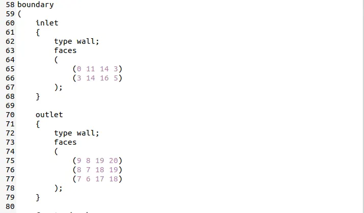
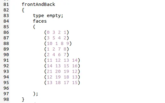
boundary specify the faces of the inlet, outlet and walls as shown in figure below.
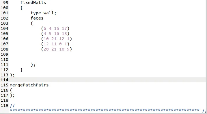
controlDict_file:
It specifies the start, end time and delta T of the simulation:

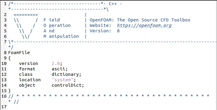
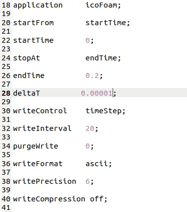
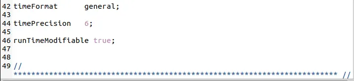
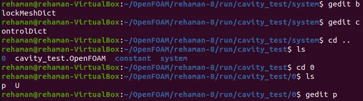
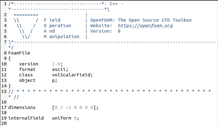
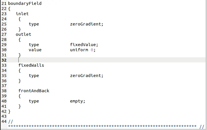
Now define the initial value for pressure and velocity. we have to go to the intial condition file named as 0.
Initial setting for Pressure:
Initial setting for Velocity:
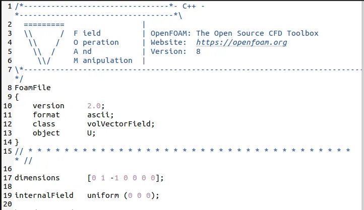
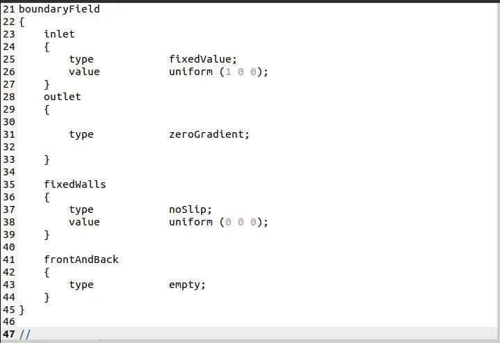
We set the problem statement, now proceed to deploy the mesh using blockMesh and checkMesh. To chk the errors in our Mesh.

blockMesh:
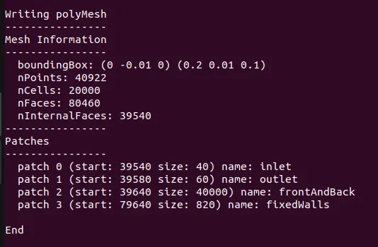
checkMesh:
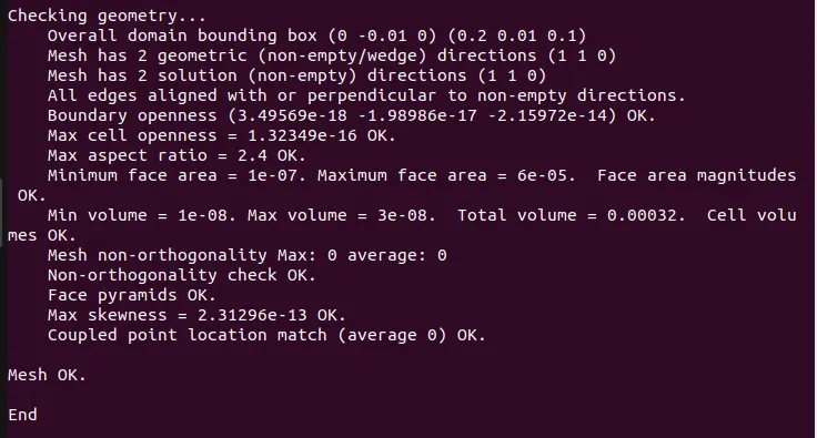
For post processing the results using paraview in openFoam.
The command for paraview is paraFoam.

Mesh:

The above mesh, it is not uniform all over the surface. let us adjust the mesh grid.

Velocity distribution:
Pressure distribution:
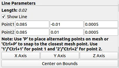
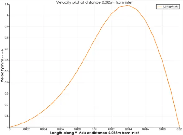
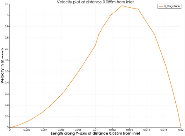
Measure the velocity profile at 0.085 m from the inlet of the geometry:
Case 2 (Grading Factor 0.2):
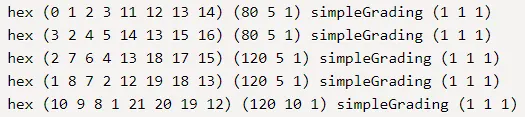
The block definitions are contained in a list named blocks. Each block definition is a compound entry consisting of a list of vertex labels a vector giving the number of cells required in each direction, the type and list of cell expansion ratio in each direction.
Then the blocks are defined as follows:
blocks
(
hex (0 1 2 3 4 5 6 7) // vertex numbers
(10 10 10) // numbers of cells in each direction
simpleGrading (1 2 3) // cell expansion ratios
);
- Cell expansion ratios:
- The third entry gives the cell expansion ratios for each direction in the block. The expansion ratio enables the mesh to be graded, or refined, in specified directions. The ratio is that of the width of the end cell along one edge of a block to the width of the start cell along that edge.Each of the following keywords specify one of two types of grading specification available in blockMesh.
- simpleGrading
- The simple description specifies uniform expansions in the local , and directions respectively with only 3 expansion ratios,
- e.g.
simpleGrading (1 2 3) - edgeGrading
- The full cell expansion description gives a ratio for each edge of the block, numbered according to the scheme, with the arrows representing the direction from first cell…to last cell e.g.
edgeGrading (1 1 1 1 2 2 2 2 3 3 3 3)
This means the ratio of cell widths along edges 0-3 is 1, along edges 4-7 is 2 and along 8-11 is 3 and is directly equivalent to the simpleGrading example given above.
Multi-grading of a block:
Using a single expansion ratio to describe mesh grading permits only “one-way” grading within a mesh block. In some cases, it reduces complexity and effort to be able to control grading within separate divisions of a single block, rather than have to define several blocks with one grading per block. For example, to mesh a channel with two opposing walls and grade the mesh towards the walls requires three regions: two with grading to the wall with one in the middle without grading.
OpenFOAM v2.4+ includes multi-grading functionality that can divide a block in an given direction and apply different grading within each division. This multi-grading is specified by replacing any single value expansion ratio in the grading specification of the block, e.g. “1”, “2”, “3” in
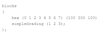
We will present multi-grading for the following example:
- split the block into 3 divisions in the -direction, representing 20%, 60% and 20% of the block length;
- include 30% of the total cells in the y-direction (300) in each divisions 1 and 3 and the remaining 40% in division 2;
- apply 1:4 expansion in divisions 1 and 3, and zero expansion in division 2.
We can specify this by replacing the -direction expansion ratio “2” in the example above with the following:
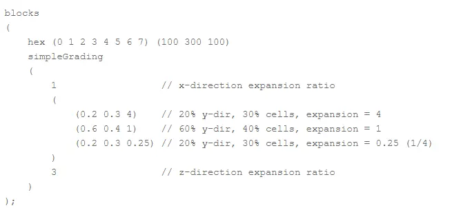
Mesh:

Velocity distribution:
Pressure distribution:
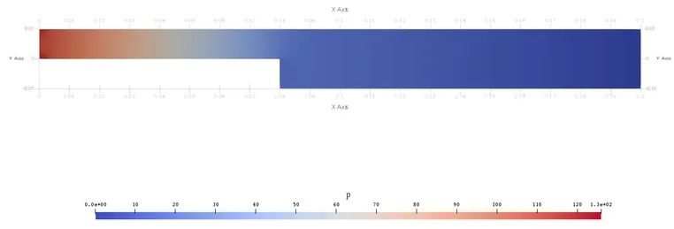
Grading factor in blockMesh is defined as the ratio of the last to first cell size, which is much better behaved that defining the number of cells and the geometric expansion ratio.
Conclusions:
To get the effective results, use the finer grading factor. suppose, if we use large number of fine elements, it could use our computation time and also require large computational memory. Use of grading is important, s that we use fine mesh to capture the flow at boundary wall and obstacles.
As grading factor increasing near step, the resolution o image in improving.
Fine mesh in the area where maximum changes happen in velocity, Pressure or other property of fluid, to capture more accurate results.