Ahmed Body Challenge
Aim: To study the aerodynamic effect of flow over a ahmed body and conduct suitable grid independence test.
Introduction: Ahmed body is standard model created by R.S Ahmed in 1984. it is similarly like car used to validation of new codes in Automotive industry.experimental data values are availble can be compared with the simulation results.
It helps to capture the various acpects of the air flow and around the vehicle and encloused to calculate the turbulance of flow around the car. it can be used for studing various properties like Drag coefficent, Lift forces, turbulence, air resistance of the car
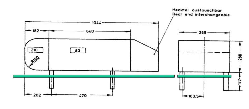
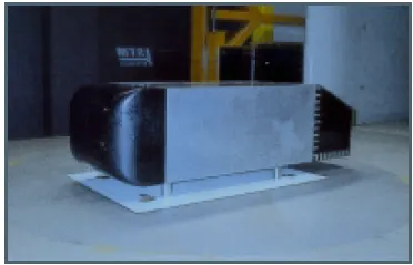
Wake Region:
The wake is the region of disturbed flow (often turbulent) downstream of a solid body moving through a fluid, caused by the flow of the fluid around the body.
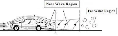
In fluid dynamics a wake may either be
The region of recirculating flow immediately behind a moving or stationary blunt body, caused by viscosity which may be accompanied by flow seperation and turbulence, or
The wave pattern on the water surface downstream of an object in a flow, or produced by a moving object (e.g. a ship), caused by density differences of the fluids above and below the free surface and gravity
The wake inside the boundary layer is the most important thing to analyze in order to determine the amount of drag (and other forces) experienced by the body.
The flow inside the boundary layer gets detached because of the adverse pressure gradient[1] . This adverse pressure gradient (i.e. flow of fluid inside the boundary layer flowing opposite to the flow of fluid directed over the body because of the motion of the body) then creates a difference in pressure ahead of the body and behind the body which increases the overall drag.
Now from the point of flow separation, inside the boundary layer, the flow gets unsteady and this unsteadiness then propagates as it moves in random fashion (distorted or discontinuous or irregular or turbulent flow). The turbulence then energise the flow closer to the surface, thereby increasing the flow velocity closer to the surface (like the golf ball).
It is turbulence of the flow what we know as the wake, inside the boundary layer.
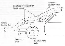
Point of Separation:
The position at which the boundary layer leaves the surface of a solid body. It may occur with the laminar flow (laminar separation) or when the boundary layer is turbulent (turbulent separation).
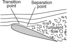
The separation point is the point where the air stops "sticking" to an object that is moving through the air. When an object is moving through the air, the air molecules push back on it and resist the object's movement - this resistance is called pressure drag. As the air flows around the object, it "sticks" to the object, forming what is known as the boundary layer. This "attached flow" is flowing very smoothly. The point on the body where the boundary layer lifts off the surface is called the separation point. When the air flow separates off the surface, the pressure drag usually increases.
Modelling Approach:
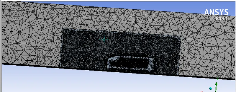
The model flow over a Ahmed body created two enclosures. one for capture the entire domain of the fluid flow with course mesh and onther one is used for capture refined mesh for better accurate results near the ahmed body.
Geometry:
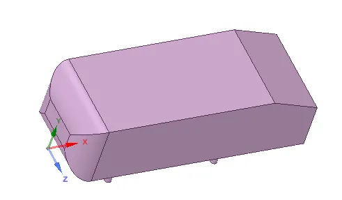
Enclosure 1:
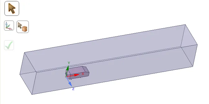
Dimensions:
1. Right face of the enclosurer is located 5m from the right side face along x axis
2. Left face of the enclosurer is located 2m from the right side face along x axis
3.Top face of the enclosurer is located 1m from the top face along y axis
4. bottom face of the encloser is attached the bottom face of the ahmed body
Base Line Simulation:
Mesh:
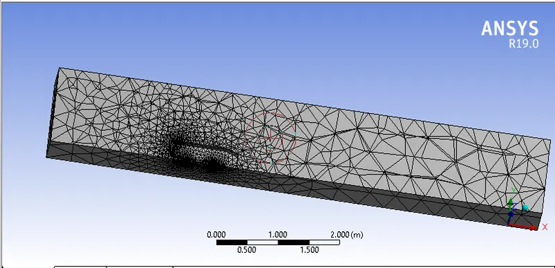
Element Size = 0.41360 m
statistics:
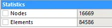
Setup:
Physics:
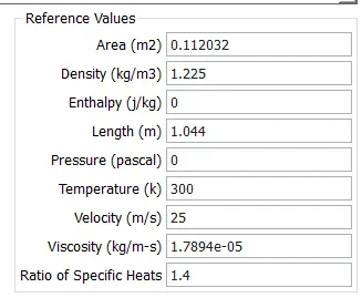
Here we using Pressure based approach because mach number less than 0.3 (velocity = 25 m/s)
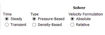
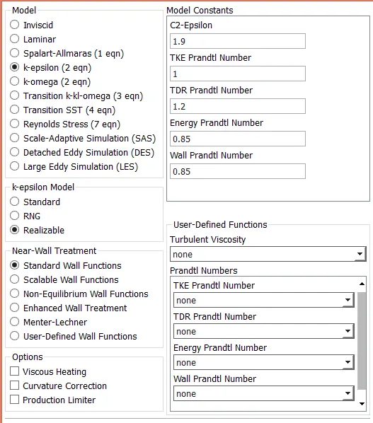
Model:
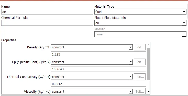
Materials: Air
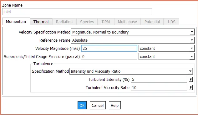
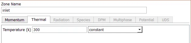
Boundary Conditions:
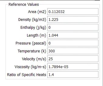
Inlet velocity = 25 m/s
Temperature = 300 K
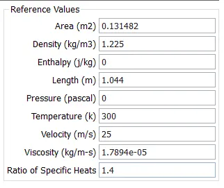
Reference values:
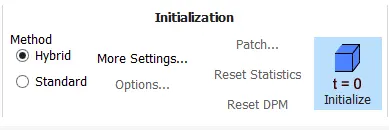
Initialization:
Plots:
Residual Polt:
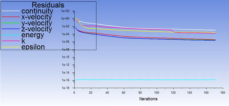
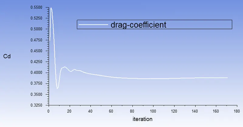
Coefficient of drag:
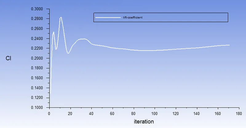
Coefficient of lift:
Post Processing:
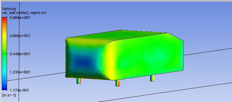
Velocity Contours:
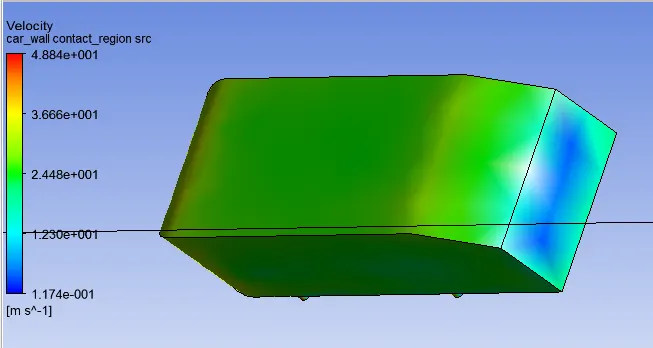
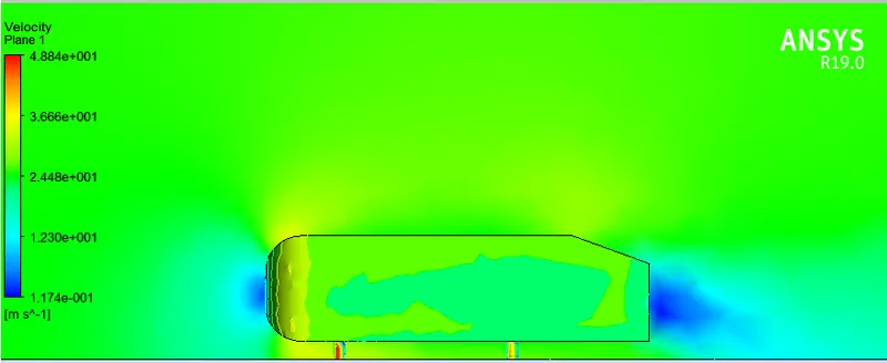
Pressure Contour:
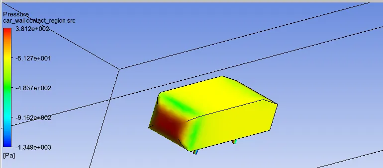
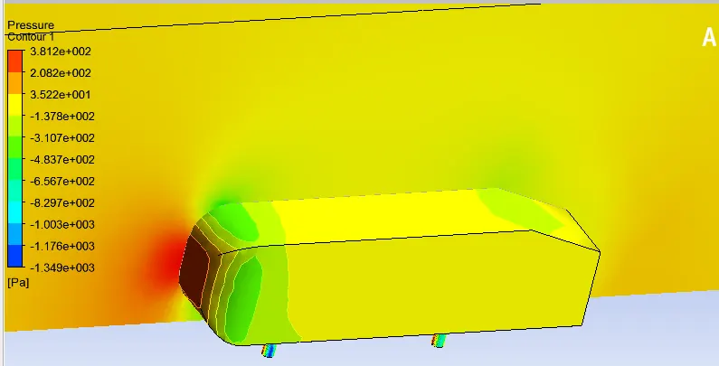
vectors:
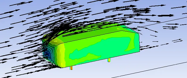
velocity vector:
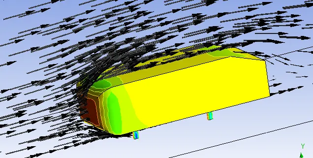
Pressure vector:
Refinement1:
Enclosure 2: samaller
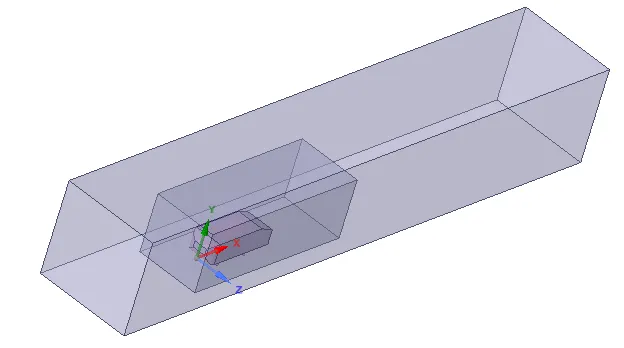
Dimensions:
1. Right face of the enclosurer is located 1m from the right side face along x axis
2. Left face of the enclosurer is located 0.5m from the right side face along x axis
3.Top face of the enclosurer is located 0.5m from the top face along y axis
4. bottom face of the encloser is attached the bottom face of the ahmed body
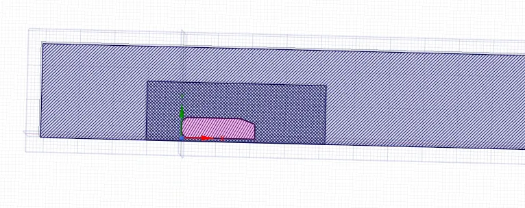
Interference:
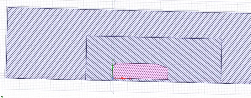
Using interference in Space claim, The mesh is not overlap in the regions (smaller enclosure). This will helps to provide the accurate results in the simulation.
Meshing:
Method: patch conforming method
Element size = 50mm
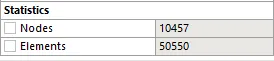
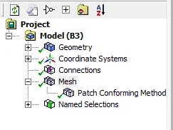
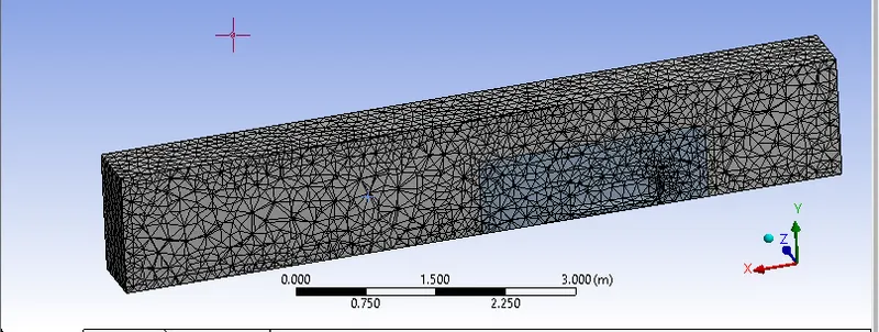
Plots:
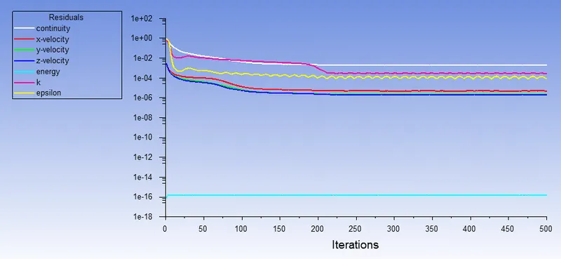
Residual Plot:
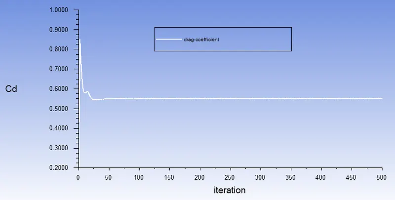
Drag Coefficent:
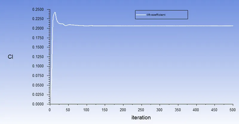
Lift coefficent:
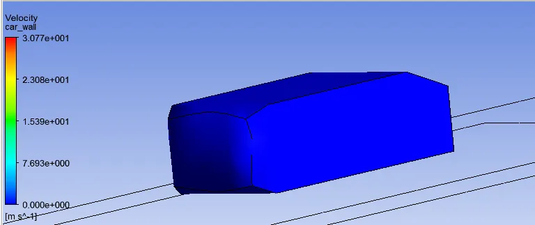
Contours:
velocity contour:
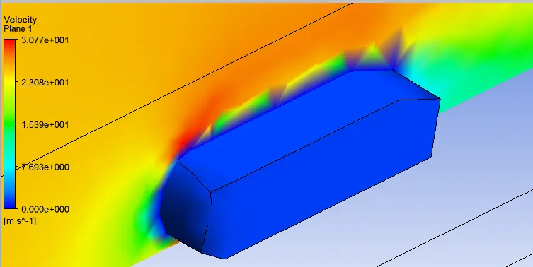
Pressure Contour:
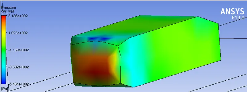
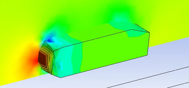
Vectors:
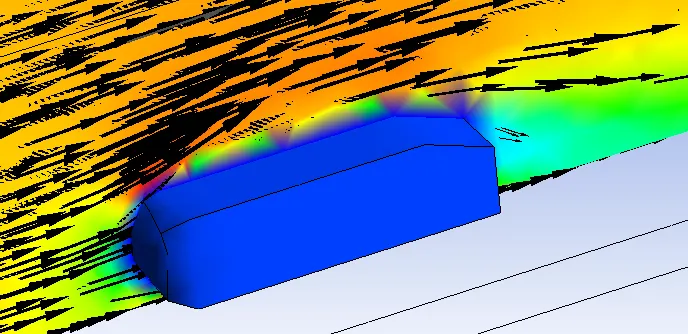
Velocity Vector:
Pressure contour:
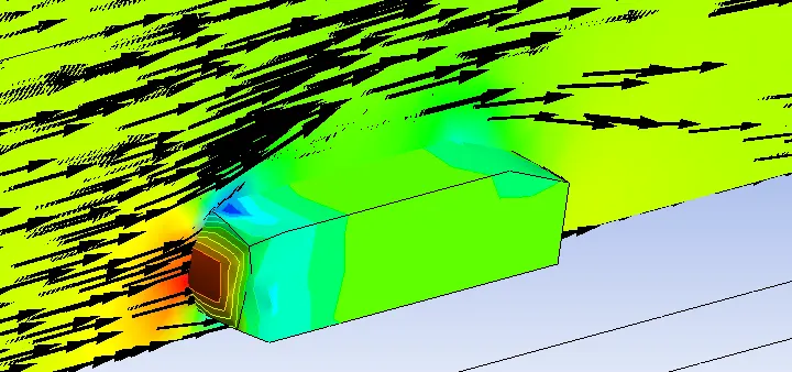
Conclusions:
1.The coeffcient off drag and lift value for this simulations are 0.55134,0.2067 respectively.
2. the drag and lift values are very low for this simulation, we have to increase the quality of the mesh.
3. in this simulation we introduce the patch conforming method for meshing
4. for this simuation wake region is not formed.
Refiniment 2:
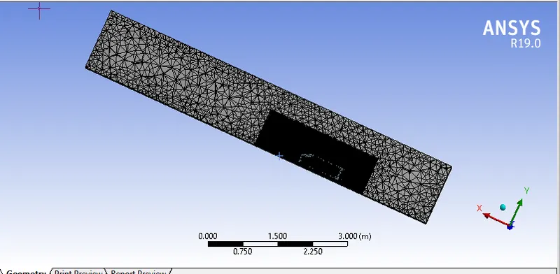
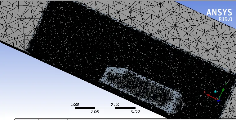
Meshing :
For bigger enclosure uses patch conforming method
element size = 50 mm
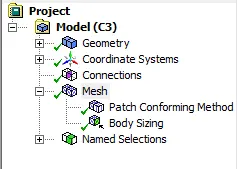
for smaller enclosure uses body sizing method
element size = 25m
Statistics:
Nodes = 155948
Elements =901440
Reference values:
Plots:
Residual Plot:
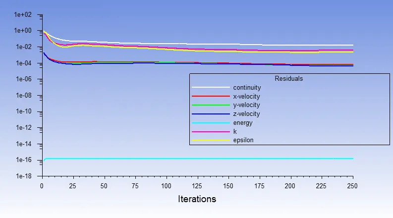
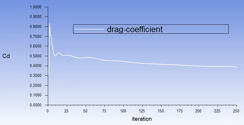
Drag Coeicent:
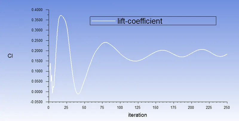
Lift coefficent:
Post Processing:
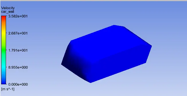
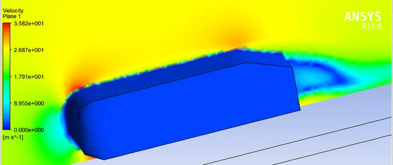
Velocity Contours:
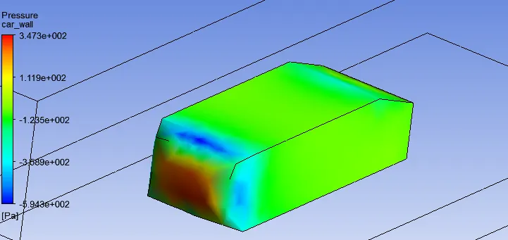
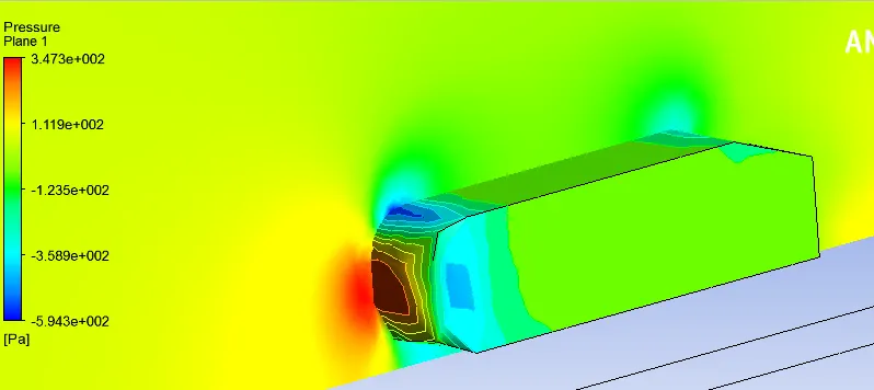
Pressure contour:
Vectors:
Velocity Vector:
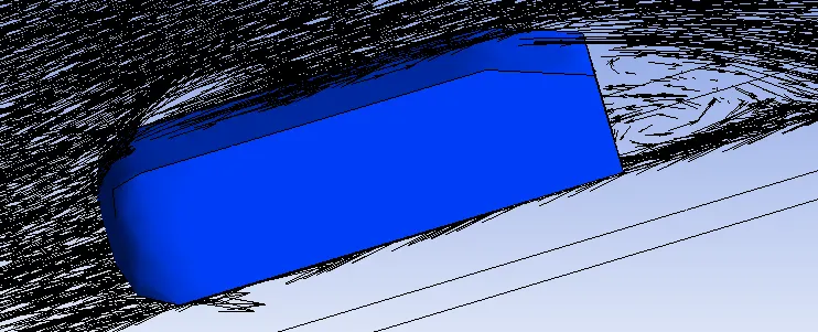
Pressure Vector:
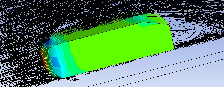
Conclusions:
1. in this simulation body sizing meshing used for smaller Enclosure having element size 25 mm
2. the coefiecent of drag and lift values are 0.3921,0.2067 respectively.
3. wake region is formed in this simulation.
Refiniement 3
Meshing :
For bigger enclosure uses patch conforming method
element size =30 mm
for smaller enclosure uses body sizing method
element size = 20mm
for Ahmed body(car wall) uses face meshing
element size = 8 mm
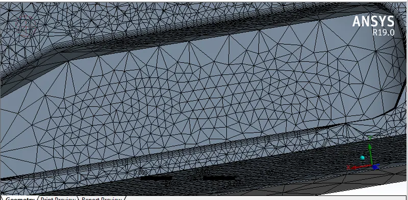
Inflation Layers = 6
for getting the total thickness of the inflation layers we are taking Y+ = 100 (for k-epslion model Y+ in between 30 to 300)
Calculating total thickness value
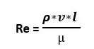
Re = 1.225*25*1.044/1.89e-05
= 1697666.66
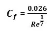
= 0.026/(1697666.66)^1/7
= 0.0026
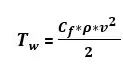
= 0.0026*1.225*(25)^2/2
= 1
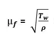
= 0.9280

= 100*1.89e-05/0.9280*1.225
= 0.001662

= 0.004956




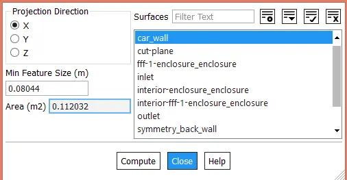
Mesh
Inflation layers:
Plots:
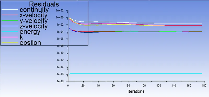
Residual Plots:
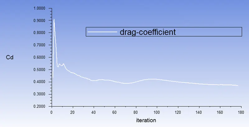
Coefficient of drag:
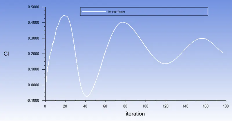
Coefficent of lift:
Post Processing:
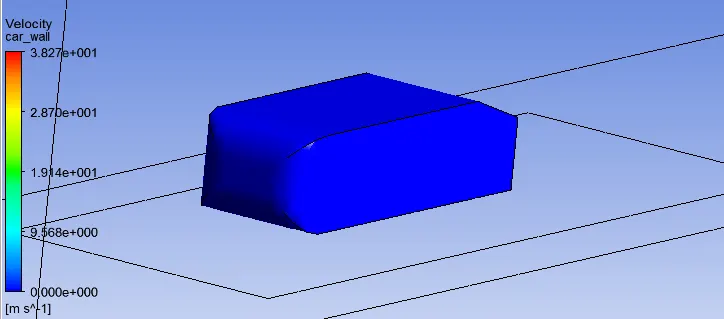
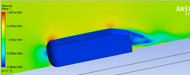
Velocity Contour:
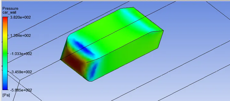
Pressure Contour:
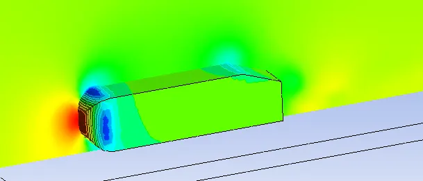
Contours:
Velocity Contour:
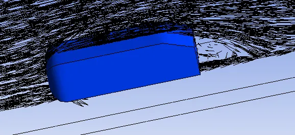
Pressure countor:
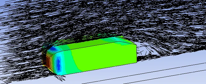
Conclusions:
1.in this simulation meshing sizes are Larger Enclosure size is 30mm and smaller enclosure size 20 mm and for Ahmed body element size is 8 mm.
2. inflation layer type mesh is used for getting accurate results
2. the coefiecent of drag and lift values are 0.3313,0.2053 respectively.
3. wake region is formed in this simulation.
Grid Independece Test:

Final Conclusions:
1. Comparing the baseline mesh the above refining mesh,
increasing the elements and nodes then the results should be accurate.
for pressure diagram shows the negative pressure
2.wake region is clear shoewn in velocity vector for the refinement of mesh.
3.slant area of the body which have low velocity.
4.the negative pressure in the ahmed body is because of bluff bodies. the boundary seperation recirculating of the flow.