Development of a Simulink model to determine Vehicle direction
Aim :- To develop a SIMULINK model to determine vehicle direction.
Objectives :-
- Development of MATLAB Simulink model as per requirement.
- Tag the requirements to the simulink model; tagging requirement 1 & requirement 2 to their corresponding subsystems is fine.
- MBD compliant changes, Data Dictionary creation & code generation is added advantage, and that is not scope of this project.
- If choosing code generation, Storage class for Input signals: ImportedExtern; Storage class for Output signal: Export to File; Storage class for local signals: localizable; Storage class for calibration signals: Const.
- Choose sample time for all signals as 0.01s
Requirements to be achieved :-
Requirement - 1:
- Steering wheel input as yaw rate (Signal name: SteeringWheel_YawDegreeInput) is the input for this system.
- This is compared against 3 angular values, one each for left turn, right turn & straight drive (Calibration Values: Right_Turn_AngularLimit, Left_Turn_AngularLimit, Straight_Drive_Steering_Angle) to say which specific direction the steering wheel is turning towards.
- Use switch blocks to compare & develop this requirement. Keep this requirement in a subsystem & output of this requirement is a local signal (Signal Name: Vehicle_Turn_Status).
Requirement – 2:
- Keep this requirement as a separate subsystem. Inputs to this requirement are local signal from requirement 1 (Signal Name: Vehicle_Turn_Status) & an input signal from camera (Signal Name: CameraInput_RoadSign), which confirms the occurrence of a road sign.
- Signal Vehicle_Turn_Status is compared against calibration values (Calibration Values: RightTurn_RoadSign, LeftTurn_RoadSign, Straight_RoadSign), if each of them is found equal, then each of the three corresponding output is compared against the camera input signal,
- Using a logical operator block, only one among them is finally given as output signal (Signal Name: Vehicle_Direction_Indicator).
Model :- The preparatiion of final model involves different stages. The each stage of doing the model by satisfying the given requirements is shown below.
Stage 1 :- Creation of SLDD file
The SLDD file is created to define the variables and signals values to the model. The steps for creating SLDD file is as follows.
1. Go to Model Explorer > File > New > Click on Data Dictionary.
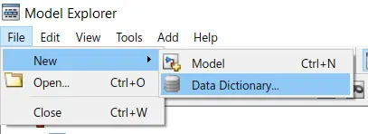
2. Assign a file name for data dictionary and save it in the current MATLAB folder.
3. Now give the input data to the data dictionary by adding Signals and parameters. After adding the Input values, the data dictionary is created. Save changes by right click on current data dictionary name.
4. Now the SLDD file is created with the required input values as shown. The Signals and Calibration data list is given in the question.
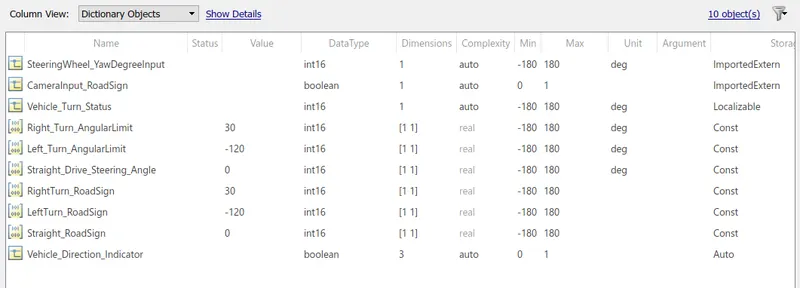
Stage 2 :- Link Data Dictionary to current model file
By doing this, the signals and constant values are automatically assigned to the input signals and blocks which we are created in Model. For this
1. Go to Modeling tab and Click on Link to Data Dictionary under Repositories.
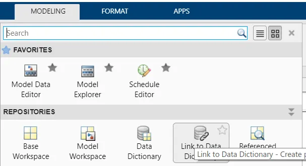
2. In the Dialogue box appeared, click on browse and select the created SLDD file. Uncheck the Enable model acces to base workspace, because the variables and signals are already defined in Model workspace as SLDD file. Click OK.
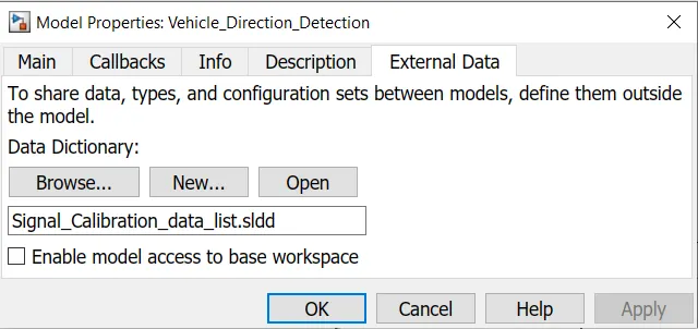
Stage 3 :- Creating Subsystems for requirements
There are total 2 requirements to be fulfilled. For this create 2 new subsystems and name them as Requirement_1 and Requirement_2. Under the each requirement subsystem, the requirement logic will be modeled.
Stage 4 :- Modelling of requirement 1
1. The requirement 1 is modelled as shown.
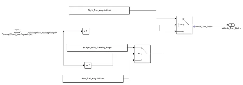
2. As specified in the requirement, the steering wheel yaw rate is input to the system. And this is compared against the Right turn and left turn angular limits and straight drive with the help of Switch cases. The comparision is done by using relational operator and output of this system is named as Vehicle_Turn_Status as mentioned in the requirement.
Stage 5 :- Modelling of requirement 2
1. The modelling of requirement 2 is shown below.
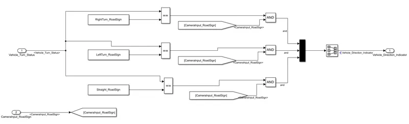
2. The inputs for this Requirement 2 is output from requirement 1 and input signal from camera (CameraInput_RoadSign).
3. The vehicle turn status is compared against the calibrated values for each road sign. If any of the case matches, it is compared against CameraInput_RoadSign using AND operator.
4. Based on the vehicle direction and camera input, only one turn indcation is sent as output and named as Vehicle_Direction_Indicator.
5. After modelling of requirements, keep the both requirement subsystems in a Subsystem which is given 2 inputs of SteeringWheel_Yaw input and CameraInput_RoadSign and output as Vehicle_Direction_Indicator.
Stage 6 :- Signals Resolving and Propagation
The signals must be resolved at first time when they enter the Model and then Propagated till the end upto which a particular signal has to go. For this Resolving and Propagation the following steps are to be performed.
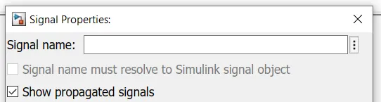
1. Go the signal properties by right click on the signal line. Then a dialogue will appear as shown.
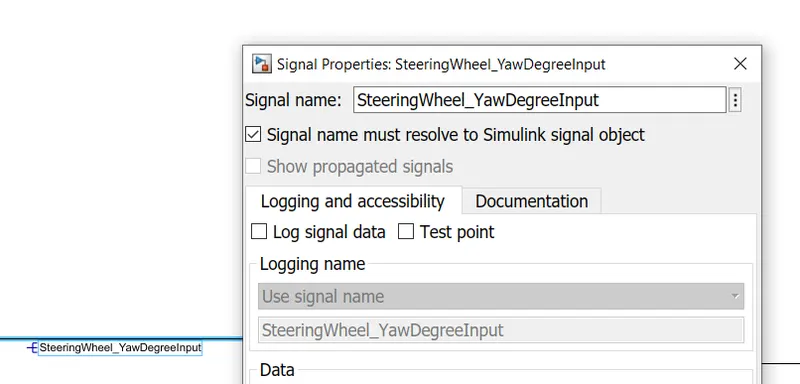
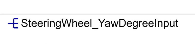
2. Name the signal as mentioned in the SLDD and check 'Signal Name must resolve to Simulink signal object'. Then click OK. Then the signal is resolved with a symbol as shown.
3. Then propagate this signal by naming the next same signal line with "<>". This automatically creates propagation for the previous resolved signal.

4. Alternatively, go the properties and check the 'Show propagated signals'.
5. The above Resolving and propagation of signals is done for every signal. Then model is completed for Testing.
Step 7 :- Changing Model settings
1. Go to model settings and in solver selection change Solver type to Fixed-step and discrete solver.

2. The simulation and sample time can be changed while performing the testing because they are dependent on Test cases.
Final Model :- After following the above Stages, the model is ready for testing. The model created is shown below wiith subsystems.


Requirement Tagging :- The requirement tagging is necessary for inorder to check what are the requirements for created substem in the project support documentation. For this requirement tagging the below steps are to be followed.
1. A word document is created with Necessaru requirements and saved in the current/same matlab directory in which model is present.
2. Select the title of the requirement to be tagged lets say Requirement_1 and naviagate to simulink window as shown.
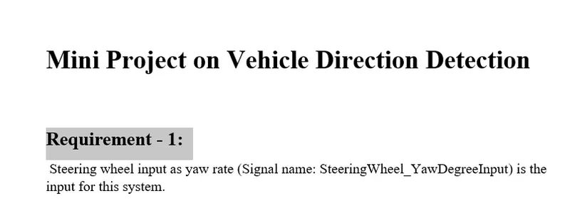
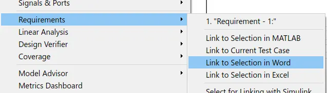
3. Right Click on Requirements_1 subsystem, click on 'Requirements' and 'Link to Selection in Word'. Then the tag is appear as "Requirement - 1" shown below.
4. The same process should be done for Requirement_2 also.
Model Compliance Check :- In this process, the model is checked for compliance with necessary modeling guidelines and standards.
1. Go to Modeling tab and Click on 'Model Advisor'.
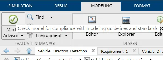
2. Choose the System Hierarchy. Click on main model so that whole model is checked by following Model Hierarchy.
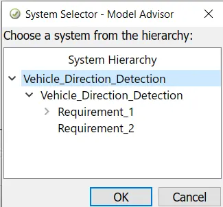
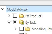
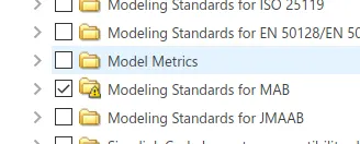
3. Model Advisor window willl appear. In that window select 'By Task' and Check the Modeling Standards for MAB.
4. Click on run selected checks. After that the summary is shown for Pass cases, Fail cases and warning. The model must not have any Fail conditions and warnings should be as low as possible.
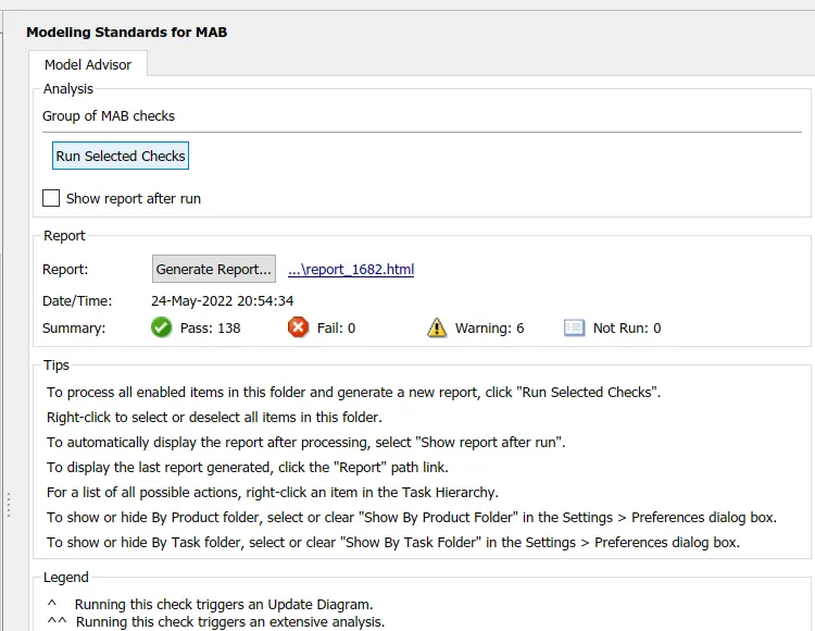
5. The warnings can be rectified by taking the suggested actions.
Testing of the Model :-
The Model In loop (MIL) and Software In loop (SIL) tests are done to the model. Before testing the test cases must be developed. The test case file contains the inputs and expected outputs.
Developing of test cases
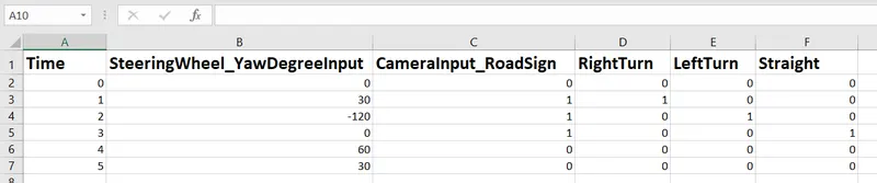
1. The behaviour of the model is studied. The necessary inputs are given and they are matched with expected outputs.
2. For the given model the inputs are Steering Wheel angle which determines the vehicle direction as left, right or straight and CameraInput_Road sign which is a boolean value.
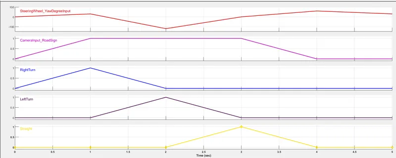
3. For right turn the maximum SteeringInput angle is below 30 deg, for left turn it is below -120 deg and for straight drive it is zero.
4. By considering the above inputs, the test case is created in Excel as shown. At each second each test case is given in the form of ramp.
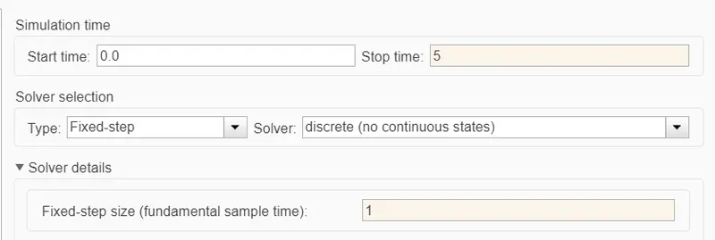
Changing Simulation Settings
1. Change the simulation time to 5 seconds and sampling time as 1 second.
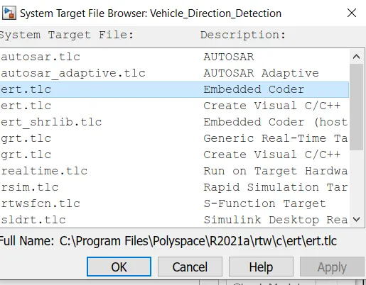
2. Go to code generation and select the Embedded Coder.
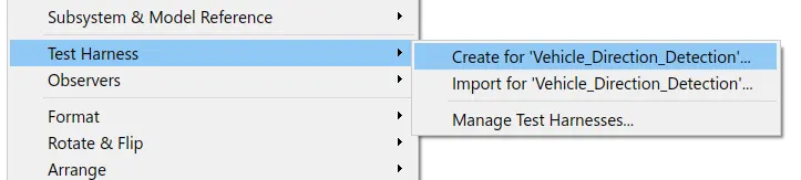
Creating Test Harness environment
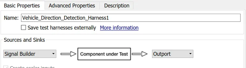
1. Right Click on Required Vehcle_Direction_Detection subsystem, Go to Test Harness and click on 'Create for " Vehcle_Direction_Detection" '.
2. From basic properties, select the Source as signal builder and Sink as output port.
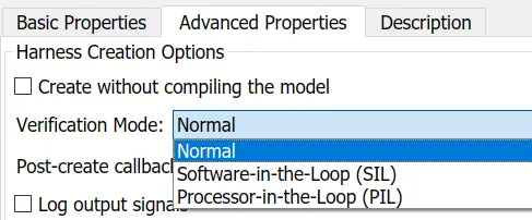
3. From advanced properties, select Normal for MIL test and Software-in-the-loop for SIL test.
Model-In-Loop (MIL) Test :-
1. The environment for MIL test is created and there are some changes for Model is done to perform the test cases and for verification whether the outputs from model are matched with expected
outputs.
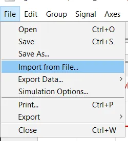
2. In the signal builder, the signals are created by importing the data from Test Cases Excel file. For this Go to signal builder > File > Import from file.
3. Select the required excel file by using browse option and import the data. The signal builder is created as shown.
4. The demux block is used to seperate the output turn indications. These output values are subtracted from expected output values to analyze whether both the expected output and output values are same or not. The model is then shown like below.
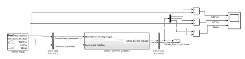
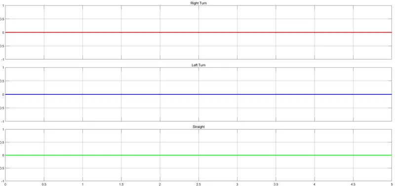
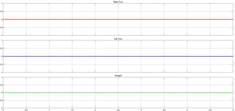
Observations for MIL test :- After running the MIL test it is observed that the difference between actual output and expected output is zero which indicates the model is correct and passed the MIL test.
Software-in-the-Loop (SIL) test :-
1. The steps and modifications for SIL test is same as of MIL test.
2. In SIL test, treat the subsystem as Atomic unit on which test is performing. To do this right click on subsystem, go to block parameters and check "Treat as atomic unit" and click ok.
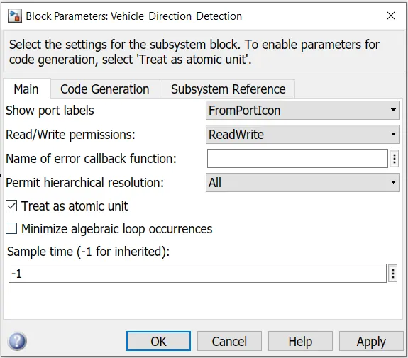
3. The creation of signals in signal builder and making changes in model for output verification is same as done in MIL test.
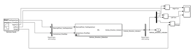
Observations for SIL test :- After running the SIL test it is observed that the difference between actual output and expected output is zero which indicates the model is correct and passed the SIL test.
Code generation :-
1. Go to apps and select the Embedded Coder.
2. Click on Build option appeared.
Generated Code :-
/*
 * File: Vehicle_Direction_Detection.c
 *
 * Code generated for Simulink model 'Vehicle_Direction_Detection'.
 *
 * Model version                  : 1.9
 * Simulink Coder version         : 9.5 (R2021a) 14-Nov-2020
 * C/C++ source code generated on : Wed May 25 16:23:52 2022
 *
 * Target selection: ert.tlc
 * Embedded hardware selection: Intel->x86-64 (Windows64)
 * Code generation objectives: Unspecified
 * Validation result: Not run
 */

#include "Vehicle_Direction_Detection.h"
#include "Vehicle_Direction_Detection_private.h"

/* Exported data definition */

/* Const memory section */
/* Definition for custom storage class: Const */
const int16_T LeftTurn_RoadSign = -120;/* Referenced by: '/Constant1' */
const int16_T Left_Turn_AngularLimit = -120;/* Referenced by: '/Constant2' */
const int16_T RightTurn_RoadSign = 30; /* Referenced by: '/Constant' */
const int16_T Right_Turn_AngularLimit = 30;/* Referenced by: '/Constant' */
const int16_T Straight_Drive_Steering_Angle = 0;/* Referenced by: '/Constant1' */
const int16_T Straight_RoadSign = 0;   /* Referenced by: '/Constant2' */

/* External outputs (root outports fed by signals with default storage) */
ExtY_Vehicle_Direction_Detect_T Vehicle_Direction_Detection_Y;

/* Real-time model */
static RT_MODEL_Vehicle_Direction_De_T Vehicle_Direction_Detection_M_;
RT_MODEL_Vehicle_Direction_De_T *const Vehicle_Direction_Detection_M =
  &Vehicle_Direction_Detection_M_;

/* Model step function */
void Vehicle_Direction_Detection_step(void)
{
  /* local block i/o variables */
  int16_T Vehicle_Turn_Status;

  /* Outputs for Atomic SubSystem: '/Vehicle_Direction_Detection'
   *
   * Block description for '/Vehicle_Direction_Detection':
   *  Contains Requirement Subsystems
   */
  /* Switch: '/Switch' incorporates:
   *  Constant: '/Constant'
   *  Constant: '/Constant'
   *  Inport: '/SteeringWheel_YawDegreeInput'
   *  RelationalOperator: '/Compare'
   *  RelationalOperator: '/Compare'
   *  Switch: '/Switch1'
   */
  if (SteeringWheel_YawDegreeInput > 0) {
    /* Switch: '/Switch' incorporates:
     *  Constant: '/Constant'
     */
    Vehicle_Turn_Status = Right_Turn_AngularLimit;
  } else if (SteeringWheel_YawDegreeInput == 0) {
    /* Switch: '/Switch1' incorporates:
     *  Constant: '/Constant1'
     *  Switch: '/Switch'
     */
    Vehicle_Turn_Status = Straight_Drive_Steering_Angle;
  } else {
    /* Switch: '/Switch' incorporates:
     *  Constant: '/Constant2'
     *  Switch: '/Switch1'
     */
    Vehicle_Turn_Status = Left_Turn_AngularLimit;
  }

  /* End of Switch: '/Switch' */

  /* Outport: '/Vehicle_Direction_Indicator' incorporates:
   *  Constant: '/Constant'
   *  Constant: '/Constant1'
   *  Constant: '/Constant2'
   *  Inport: '/CameraInput_RoadSign'
   *  Logic: '/AND'
   *  Logic: '/AND1'
   *  Logic: '/AND2'
   *  RelationalOperator: '/Relational Operator'
   *  RelationalOperator: '/Relational Operator1'
   *  RelationalOperator: '/Relational Operator2'
   */
  Vehicle_Direction_Detection_Y.Vehicle_Direction_Indicator[0] =
    ((Vehicle_Turn_Status == RightTurn_RoadSign) && CameraInput_RoadSign);
  Vehicle_Direction_Detection_Y.Vehicle_Direction_Indicator[1] =
    ((Vehicle_Turn_Status == LeftTurn_RoadSign) && CameraInput_RoadSign);
  Vehicle_Direction_Detection_Y.Vehicle_Direction_Indicator[2] =
    ((Vehicle_Turn_Status == Straight_RoadSign) && CameraInput_RoadSign);

  /* End of Outputs for SubSystem: '/Vehicle_Direction_Detection' */
}

/* Model initialize function */
void Vehicle_Direction_Detection_initialize(void)
{
  /* (no initialization code required) */
}

/* Model terminate function */
void Vehicle_Direction_Detection_terminate(void)
{
  /* (no terminate code required) */
}

/*
 * File trailer for generated code.
 *
 * [EOF]
 */
Result :-
Hence, the model for Vehicle direction detection is modelled in Simulink with the given requirements. The model compliance is also done and MIL and SIL tests are performed. The Code is generated by using embedded coder. Hence the objectives of the project are achieved.