State of charge estimation
Question 1:- Simulate the 3 test cases from harness dashboard and write a detailed report on the results.
Answer:-
Battery Management System (BMS) :-
Battery management system (BMS) is technology dedicated to the oversight of a battery pack, which is an assembly of battery cells, electrically organized in a row x column matrix configuration to enable delivery of targeted range of voltage and current for a duration of time against expected load scenarios. The oversight that a BMS provides usually includes:
1. Monitoring the battery
2. Providing battery protection
3. Estimating the battery’s operational state
4. Continually optimizing battery performance
5. Reporting operational status to external devices
Model :-
*The BMS model is download from given link and the project is loaded in MATLAB.
* The BMS closed loop model and dash board for the model is loaded in simulink.
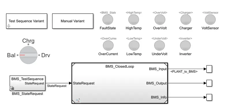
* The test cases can be choosen from Test sequence varient from Dashboard.
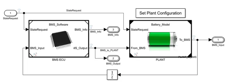
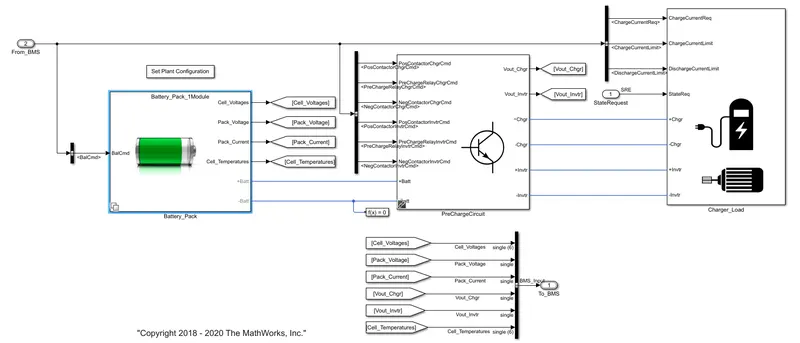
The model and dashboard are shown below. The model consists of battery pack and BMS Electronic control unit.
By using set plant configuration, no of modules in a battery pack can be selected. For this simulation only one module is selected.
The BMS ECU:-
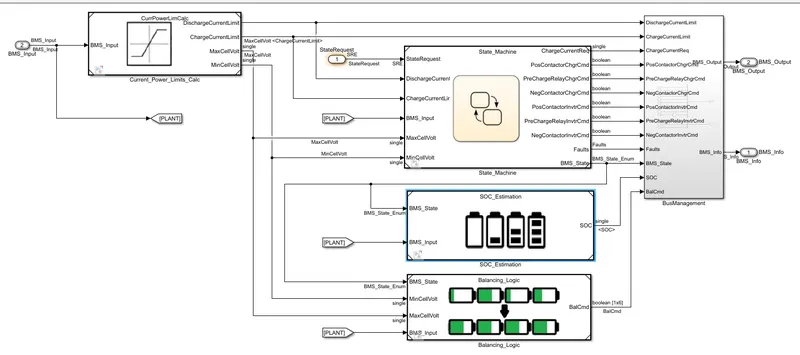
The insde subsystem of BMS ECU is shwon below. It consists of State Machine, SOC estimation and Battery balancing algorithms. The state machine evaluates the fault monitoring, Cell temperature monitoring etc. The SOC estimation block determines the SOC of the battery pack using Coulomb counting, UKF(Unscented Kalman filters) and EKF(Extended Kalman Filter) algorithms. Balancing technique used here is active balancing.
Battery Plant :-
It consists of battery pack and precharge circuit. In this model we have taken one battery module with 6 cells in it. There are different subsystems for Batteries and battery monitoring. A precharge circuit allows the current to flow in a controlled manner until the voltage level rises to very near the source voltage before the main contactors are permitted to close.
Simulation :-
The simulation is run in 3 different test cases. Each test case consists of different test sequences. These test sequences helps us to understand and monitor BMS under different conditions, so BMS operation can be evaluated under certain given conditions.
The drive load is given by battery drive cycle data.
Test Case 1 :-
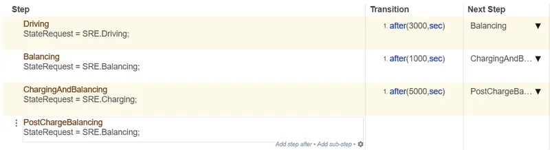
The test case 1 consists of the following sequences. The simulation is run for 20000 seconds.
Results for Test Case 1:-
All the dashboard lamps turned green indicating no fault detected in simulation.
The Indivual cell voltage, Battery pack current, SOC by using different algorithms, Each cell temperature and battery balancing command are shown below.
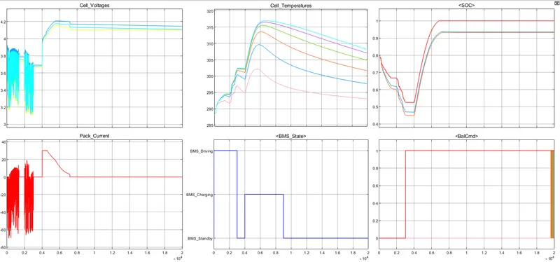
* During driving of first 3000 seconds, the individual cell voltage is around 3.8 - 4v and pack current reaches upto 18 A.
* The individual cell voltage reaches upto 4.2 voltage which is maximum voltage for Li-ion cell incase of charging state from 3000 seconds.
* The cell maximum temperature is around 315k to 320k and that too it reached after driving and charging.
*The BMS is active during charging so temperature is then lowered significantly after reached to 315k. During cell balancing the BMS is on standby mode only.
*The SOC estimation for 3 different algorithms is shown. From that SOC graph the precision between 3 algorithms is not good and The soc is dropped upto 45%.
Test Case 2 :-
The test case consists of the following sequences. It only consists of driving and charging. The simulation is run for 20000 seconds.

Results for Test Case 2 :-
Even though the model is run for 2000 seconds, it is only run upto around 9000 seconds because the SOC dropped to 0%. The Indivual cell voltage, Battery pack current, SOC by using different algorithms, Each cell temperature and battery balancing command are shown below.
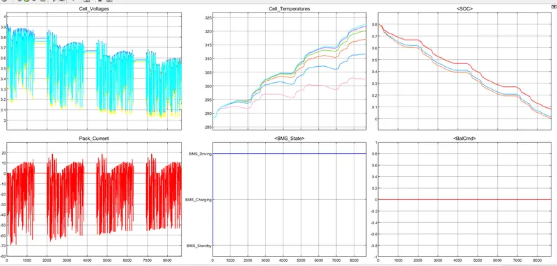
* The battery is fully drained in less than 10000 seconds.
* The BMS is active in Driving state during the simulation as driving is the only process takes place.
* We can clearly observe the 3rd soc estimation which is Extended Kalman Filter algorithm shows the accurate SOC estimation as when it reaches to zero, the simulation is stopped.
* The pack current and voltages behave according to input battery drive cycle load. Four battery drive cycles can be performed with full charge of battery pack in given model.
* This test sequence doesn't involved cell balancing hence the cell balancing command is in OFF state throught the simulation.
* The highest cell temperature can reach upto 323K.
Test Case 3 :-
It consists of only charging of battery pack. The simulation run for 2000 seconds.

Results for Test Case 3:-
The Indivual cell voltage, Battery pack current, SOC by using different algorithms, Each cell temperature and battery balancing command are shown below.
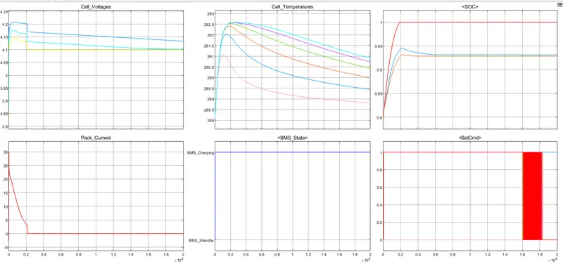
* The BMS stays in charging mode throught the simulation which satisfies the test case.
* Maximum cell voltage reached to 4.2 V as maximum charging voltage is limited to 4.2V for lithium ion cell.
* The SOC is reached to 100% within around 2000 seconds. The current supplied to battery pack is stopped from 2000 seconds.
* As shown in graph, the current supply is 0 A from 2000 seconds which tells the BMS is working and ensures no extra current to battery after fully charged.
* The temperature of battery pack is controlled throught the charging and maximum cell temperature reached is
Question 2 :- What is coulomb counting? Refer to the above model and explain how BMS implements coulomb counting for SOC estimation ?
Answer :- SOC of a battery is the ratio of stored charge (in Ah) at time instant 't' to the nominal capacity(μn) in Ah.
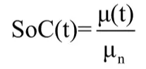
The coulomb counting method charging or discharging current of battery and integrates their values in overtime inorder to estimate SOC. The SOC can be calculated as
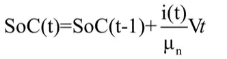

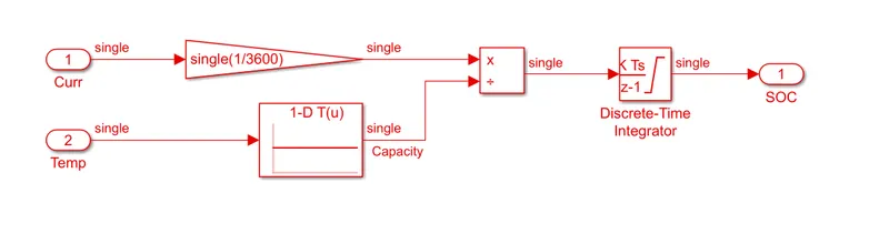
The coulomb counting for SOC estimation in our model is implemented as shown. The current in A is converted into Ah in gain block. The lookup table provides the Capacity of battery pack with respect to different temperatures. Then the both current and capacity is divided and integrated by using Discrete - Time Integrator to estimate SOC. The integrator follows Forward Euler's method.