Week-11 Challenge: Braking
The challenge is done simple and straight to point as per instructions received from trainer in Live sessions. Please consider this while grading.
Question 1:- For a defined driving cycle, calculate the energy required for braking.
Answer :- In this challenge, FTP drive cycle is considered. The formula for braking energy is
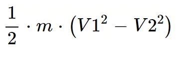 where V1 is initial velocity and V2 is final velocity after deceleration.
For this matlab script is used for calculations. The drive cycle data is taken from https://www.epa.gov/sites/default/files/2015-10/ftpcol.txt and copied in excel and then imported to workspace.
Code :-
clear all
close all
clc
M = 1000; %Mass in kg

%Reading drive cycle data from Excel sheet
FTP = xlsread('FTP.xlsx');
T = FTP(:,1);  %Time in Seconds
S=FTP(:,2);  %Speed in mph

%Converting mph into m/s
V = S./2.237 ; %Speed in m/s

for i= 1:(length(V)-1)
    if V(i)>V(i+1)
        BE(i) = (0.5*M*(V(i)^2-V(i+1)^2))./(1000*3600); %In kWh
    end
end

Total_Braking_Energy_in_kWh = sum(BE)  %in kWh

figure
subplot(2,1,1)
plot(T,V)
xlabel('Time in seconds')
ylabel('Speed in m/s')
title('FTP drive cycle')

subplot(2,1,2)
plot(BE)
xlabel('Time in seconds')
ylabel('Braking Energy in kWh')
title('Braking Energy of FTP drive cycle')
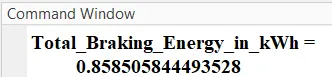
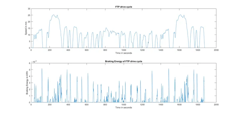
Results :- From the above calculations the Braking energy for FTP drive cycle is 0.8585kWh. The graphs showing drive cycle and braking energy are shown below.
Question 2:- Why electric motor can’t develop braking torque at high speed similar to starting? How electric and mechanical brakes are coordinated?
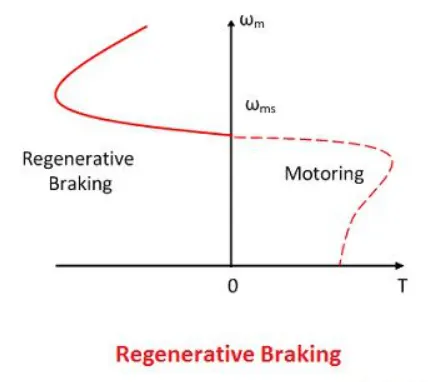
Answer :- The torque speed characterstics of the induction motor is shown below. At high speeds the torque will be decreased. As we know that motor exhibits similar characterstics when used in reverse energy flow such as regenerative braking. During these high speeds the braking torque produced is not enough to decelerate the vehicle at a faster rate and additional braking help is required from mechanical components such as disk brakes and drum brakes.
The electric and mechanical brakes are coordinated in a EV. In practical cases relying only on regenrative braking is a major saftey concern because of braking torque shortage. There are 2 control strategies helps in coordination of electric and mechanical brakes.
Series braking :- The regenerative and mechanical brakes are applied one after other. The regenerative brakes are used for vehicle deceleration and mechanical brakes are used to make vehicle stop.
Prallel braking :- The regenrative and mechanical brakes are applied simultaneously so that vehicle halt faster.
Question 3 :- Make a MATLAB program which plots contour of given motor speed, torque and efficiency values.
Answer :- The necessary formulae and conversions are mentioned in matlab script in the form of comments. The input data is assumed arbitrarily.
Code :-
clear all
close all
clc

% Motor Inputs, assumed arbitrarily
w = linspace(1,1200);    % Angular Velocity in rad/s
T = linspace(1,500);     % Torque assumed
Kc = 0.1;                        % Constant for copper loss
Ki = 0.006;                     % Constant for Iron loss
Kw = 0.0001;                 % Constant for windage loss
C1 = 20;                         % Motor loss constant

% Creating meshgrid
[A,B] = meshgrid(w,T);

% Power Calculations
P_out = (A.*B);   %Motor output power
P_copper = (B.^2)*Kc;       %Copper loss
P_iron = A.*Ki;                   % Iron loss
P_windage = (A.^3)*Kw;   %Windage loss
P_in= P_out + P_copper + P_iron+P_windage+C1;  %Motor input power after adding losses

Efficiency = P_out./P_in;

%Contour Plotting
N = [0.75,0.8,0.85,0.86,0.87,0.88,0.89,0.9,0.91,0.92,0.93,0.94,0.95]; %Contour Mapping

figure
box off
grid off
contourf(A,B, Efficiency,N)
colorbar
title('Torque-Speed-Efficiency contour of an induction motor')
xlabel('Angular velocity of rotor in rad/s')
ylabel('Induced Torque in Nm')
zlabel('Motor Efficiency')
Results :- The contour graph showing velocity, torque and efficiency is shown below.
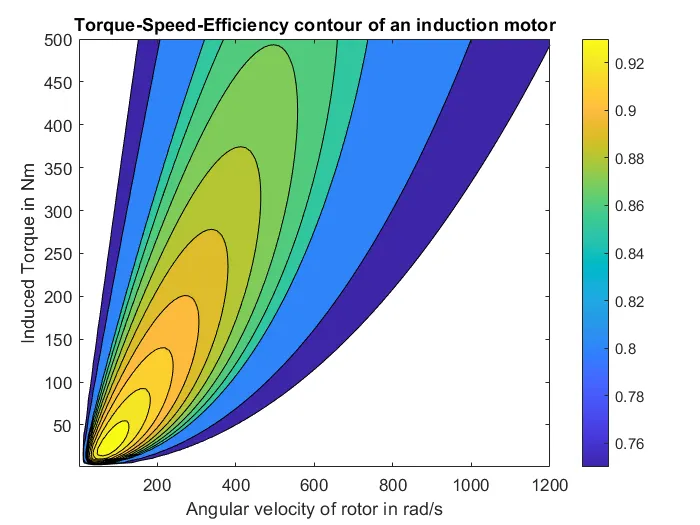
From the above graph it is observed that under 200rad/sec (1910 rpm) The motor runs efficiently as high as 92%.