Implementation of Control Logic and State Flow of Washing Machine and Gear Box
CHALLENGE 1 :-
Aim :-
- Implement control logic of a “washing machine” using Stateflow as per given sequence:
- If the power supply is available, the system gets activated
- If the Water supply is not available, stop the process & indicate through LED
- Soaking time should be 200s followed by Washing time of 100s.
- Then rinsing happens for next 20s & dryer runs for 50s.
The simulation is run in 3 cases, in 1st case the water and power supply are continuously and in second case the water supply is stopped and in 3rd case the power supply is stopeed at middle of simulation so that the system switches/transistion to OFF state.
Case 1 :- When the power supply and water are available throught the washing.
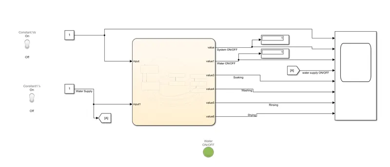
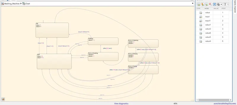
Model :- The model and control logic state flow is shown in the chart given below. The model is developed using basic simulink blocks. The power supply and water supply is taken in the form of constants and switches are assigned to both the supplies. The chart consists of ON and OFF states with input values 0 and 1. By using intermittent conditions if the input is greater than 0, the system transtion to next stage, otherwise it will transtition to OFF state. It happens for every state like Soaking, Washing, Rinsing and Drying.
Results:-
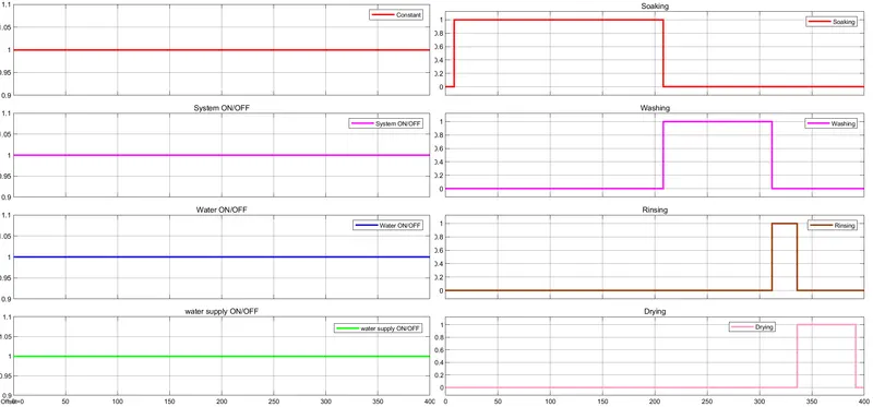
Hence from the above graph it is observed that by providing continous supply of water and power, the required operations are done as per given requirements.
Case 2:- When the power supply is proivided but water supply is stopped.
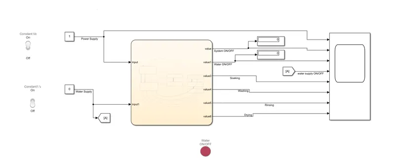
Model :- The model is shown below. The water supply shortage is indicated by LED red colour light. The control logic and state flow is same for every case.
Results :-
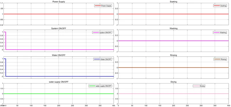
Hence from the above graph it is concluded that when the water supply is shortage, the system transistion to OFF state.
Case 3:- The water supply is provided but the power supply is interrupted at the middle of simulation. Model is same as above but only the switch is turned off at middle of simulation.
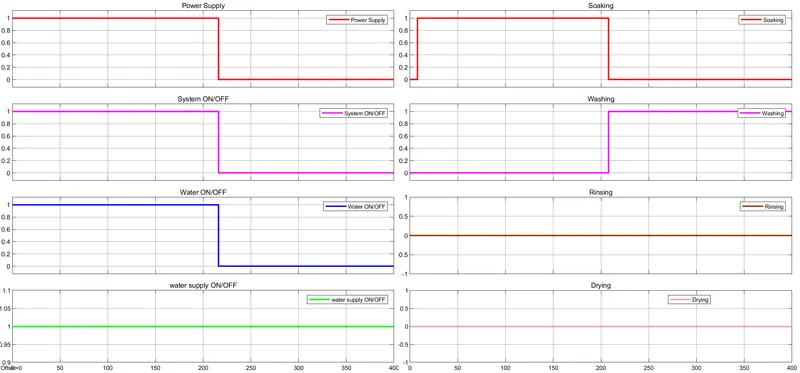
In the above graph, the power supply is stopped after 200 sec, the Rinsing and Drying are also stopped. Hence from the above 3 cases, the requirements are fulfilled.
CHALLENGE 2 :-
Aim :-
Make a Simulink chart for the “Gear shift” logic as per below conditions:
Speed Range(kmph) Gear
0 to 15 1
16 to 25 2
26 to 40 3
41 to 60 4
Above 61 5
Give speed input while the simulation is running & display the gear number.
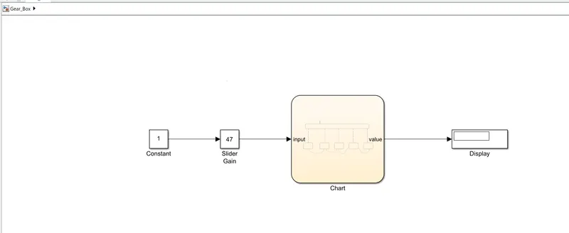
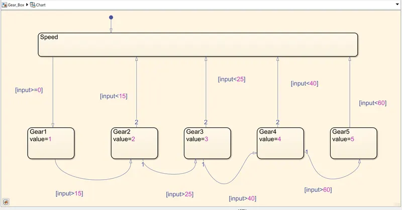
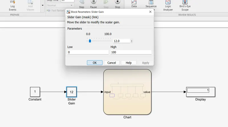
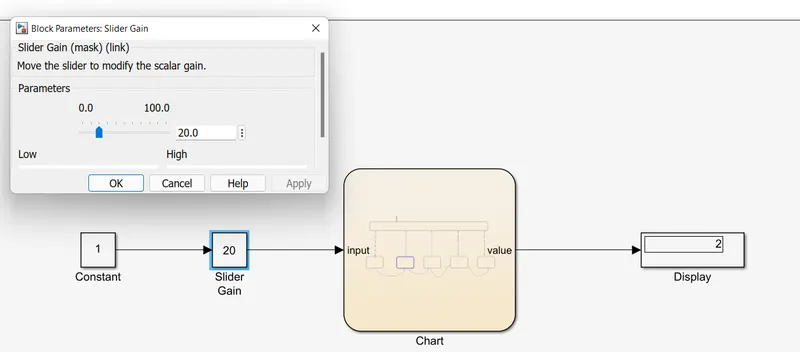
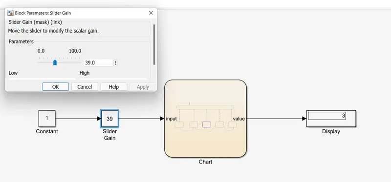
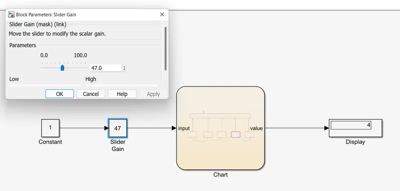
Model :- The model is studied under real time. So stop time will be infinite. The transtiton is provided in the chart below. It displayes the gear no in real time in display. Here, gear number is nothing but the value assigned in each stage. The speed is changed by using slider gain which amplifies the constant value from 1. The gear number is displayed in Display block.
Results:- 1. When speed is between 0 to 15 kmph,
2. When speed is between 16 to 25 kmph,
3. When the speed is between 26 to 40 kmph,
4. When the speed is between 41 to 60 kmph,
5. When the speed is above 60 kmph,
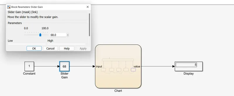
Hence, from the above results, the gear box logic is modelled with given requirements.