EV Drivetrain
Question 1 :- Which types of power converter circuits are employed in electric and hybrid electric vehicle?
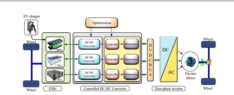
Answer :- Deping on the required application, Different types of Power convertors are used. The below figure illustrates at where in EV these power convertors are used.
1. DC/DC convertor(Chopper):-
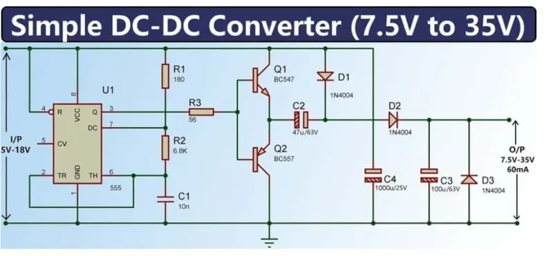
In electric engineering, a DC to DC converter is a category of power converters and it is an electric circuit which converts a source of direct current (DC) from one voltage level to another, by storing the input energy temporarily and then releasing that energy to the output at a different voltage. The storage may be in either magnetic field storage components (inductors, transformers) or electric field storage components (capacitors).The most common DC/DC converters can be grouped as follows:
A. Non-isolated converters
The non-isolated converters type is generally used where the voltage needs to be stepped up or down by a relatively small ratio (less than 4:1). And when there is no problem with the output and input having no dielectric isolation. There are five main types of converter in this non-isolated group, usually called the buck, boost, buck-boost, Cuk and charge-pump converters. The buck converter is used for voltage step-down, while the boost converter is used for voltage step-up. The buck-boost and Cuk converters can be used for either step-down or step-up. The charge-pump converter is used for either voltage step-up or voltage inversion, but only in relatively low power applications.
B. Isolated converters
Usually, in this type of converters a high frequency transformer is used. In the applications where the output needs to be completely isolated from the input, an isolated converter is necessary. There are many types of converters in this group such as Half-Bridge, Full-Bridge, Fly-back, Forward and Push-Pull DC/DC converters. All of these converters can be used as bi-directional converters and the ratio of stepping down or stepping up the voltage is high.
Reference :- https://www.intechopen.com/chapters/19583
2. DC/AC (3phase) Convertor(Inverter) :-
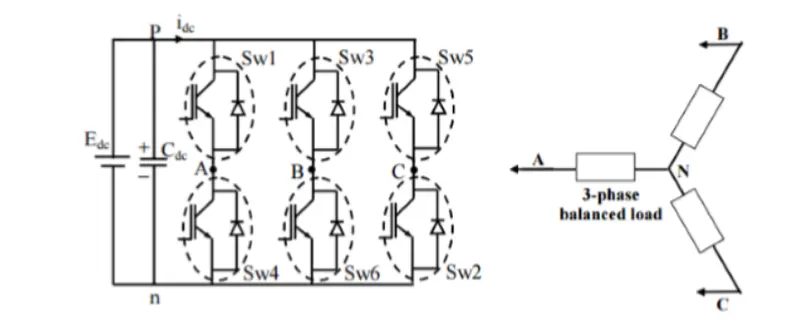
A three-phase inverter converts a DC input into a three-phase AC output. Its three arms are normally delayed by an angle of 120° so as to generate a three-phase AC supply. The inverter switches each has a ratio of 50% and switching occurs after every T/6 of the time T ( 60°angleinterval">60° angle interval) The switches S1 and S4, the switches S2 and S5 and switches S3 and S6 complement each other.
The figure below shows a circuit for a three phase inverter. It is nothing but three single phase inverters put across the same DC source. The pole voltages in a three phase inverter are equal to the pole voltages in single phase half bridge inverter.
The two types of inverters above have two modes of conduction − 180° mode of conduction and 120° mode of conduction.
180° mode of conduction :-
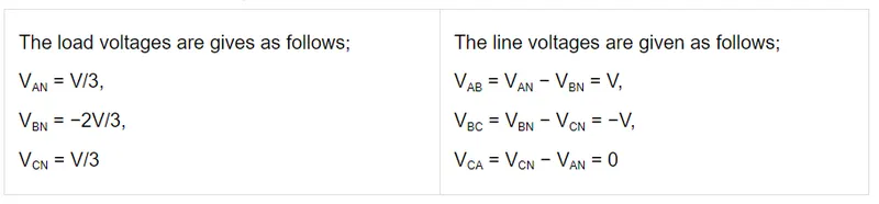
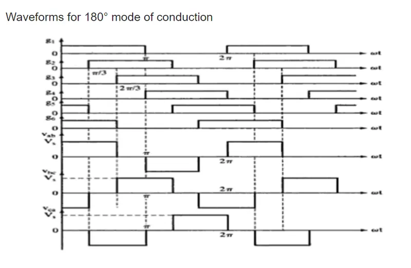
In this mode of conduction, every device is in conduction state for 180° where they are switched ON at 60° intervals. The terminals A, B and C are the output terminals of the bridge that are connected to the three-phase delta or star connection of the load.
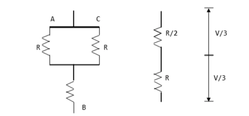
The operation of a balanced star connected load is explained in the diagram below. For the period 0° − 60° the points S1, S5 and S6 are in conduction mode. The terminals A and C of the load are connected to the source at its positive point. The terminal B is connected to the source at its negative point. In addition, resistances R/2 is between the neutral and the positive end while resistance R is between the neutral and the negative terminal.
120° mode of conduction :-
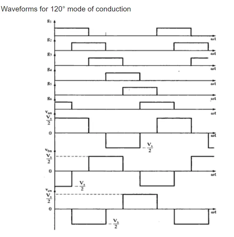
In this mode of conduction, each electronic device is in a conduction state for 120°. It is most suitable for a delta connection in a load because it results in a six-step type of waveform across any of its phases. Therefore, at any instant only two devices are conducting because each device conducts at only 120°.
The terminal A on the load is connected to the positive end while the terminal B is connected to the negative end of the source. The terminal C on the load is in a condition called floating state. Furthermore, the phase voltages are equal to the load voltages as shown below.
Phase voltages = Line voltages
VAB = V
VBC = −V/2
VCA = −V/2
3. Bidirectional AC-DC convertor :-
For EV's with regenerative braking, they usually employ a bidirectional AC-DC convertor. So that the power from motor-generator from regenerative braking is used to charge the battery without the need of another rectifier.
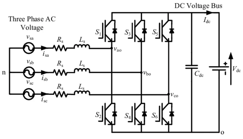
The above figure shows the three-phase bidirectional AC-DC converter topology which transfers power between the three-phase AC voltage supply and the DC voltage bus. The bidirectional AC-DC converter consists of six IGBT- Diode switches (S 1 -S 6 ), which is connected with threephase AC voltage supply through series filter inductance (L s ) and resistance (R s ). A DC capacitor (C dc ) is connected across DC voltage bus to keep the voltage (V dc ) constant.
The bidirectional AC-DC converter operates in two modes. The first mode is rectifier mode, in which the bidirectional AC-DC converter operates as a front end rectifier and allows power transfer from the three-phase AC voltage end to the DC voltage bus. The second mode is inverter mode, where the power flows from DC voltage bus to three-phase AC voltage end and the converter acts as a voltage source inverter.
Question 2 :- An Electric Vehicle's powertrain with 72V battery pack in shown in the diagram below. The duty ratio for acceleration operation is 'd1' and for the braking operation the duty ratio is 'd2'.
Given
Rated Armature voltage= 72 V
Rated armature current= 400 A
Ra= 0.5Ω, KΦ= 0.7 Volt second
Chopper Switching frequency= 400 Hz
The vehicle speed-torque characteristics are given by the below equation
 -------------1
What is EV steady state speed if duty cycle is 70%?
Answer :- The torque is also given by
---------------2
We have 2 equations for Torque, by equating those two equations the unknown variable w can be found.
The voltage V = 72*0.7 ; Given Duty cycle is multiplied.
V = 50.4 Volts
By subsistuting Given Data,
24.7 + (0.0051)w^2 = ((50.4-0.7*w)/0.5)*0.7
24.7 + (0.0051)w^2 = (50.4 - 0.7w)*1.4
24.7 + (0.0051)w^2 = 70.56 - 0.95w
By simplifying the above equation, the below quadratic equation is obtained
0.0051w^2 + 0.98w -45.86 = 0
By solving the above equation, w (+ve value is taken) = 38.914 rad/s
N (in rpm) = 60*w/2*π , N in rpm = 371.6 RPM
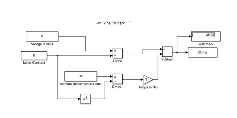
Question 3 :- Develop a mathematical model of a DC Motor for the below equation using Simulink.
ω">ω= V/Kϕ">ϕ -Ra/Kϕ">ϕ^2 .T
Answer :- By using the above equation 1, Torque can be found
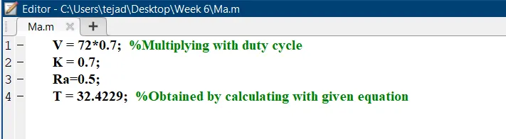
T = 24.7 + 0.0051*(38.914)^2
T = 32.4229 Nm
Now, we have all the input variables for the mathematical model. The below simulink model is the mathematical model of the given Equation.
'w' is verified and it is giving the same value as 38.92 rad/s.
Question 4 :- Refer to the blog on below topic: Induction Versus DC brushless motors by Wally Rippel, Tesla, Explain in brief about author’s perspective.
Answer :- In this blog the author Wally Rippel, Principal Power Electronics Engineer at Tesla, Shared his views on Induction Motors and Brushless DC motors. At starting of the blog the author shared about his views on IC engines and its different types. All engines are not same but depending on the requirement such as More power, Best fuel economy, and Price of the engine, the appropriate one is selected. At olden days there are lead acid batteries, DC brushed motors and contactor controllers. Today, the lead is replaced by lithium DC brushed is replaced by DC brushless motor and Induction Motors.
The author also mentioned the difference between both types of motors. Both DC brushless and induction drives use motors having similar stators. Both drives use 3-phase modulating inverters. The only differences are the rotors and the inverter controls. And with digital controllers, the only control differences are with control code. (DC brushless drives require an absolute position sensor, while induction drives require only a speed sensor; these differences are relatively small.)
One of the main differences is that much less rotor heat is generated with the DC brushless drive. Rotor cooling is easier and peak point efficiency is generally higher for this drive. The DC brushless drive can also operate at unity power factor, whereas the best power factor for the induction drive is about 85 percent. This means that the peak point energy efficiency for a DC brushless drive will typically be a few percentage points higher than for an induction drive.
In the later parts of blog the author explained the control strategies of both motors. In an ideal brushless drive, the strength of the magnetic field produced by the permanent magnets would be adjustable. When maximum torque is required, especially at low speeds, the magnetic field strength (B) should be maximum – so that inverter and motor currents are maintained at their lowest possible values. This minimizes the I² R (current² resistance) losses and thereby optimizes efficiency. Likewise, when torque levels are low, the B field should be reduced such that eddy and hysteresis losses due to B are also reduced. Ideally, B should be adjusted such that the sum of the eddy, hysteresis, and I² losses is minimized. Unfortunately, there is no easy way of changing B with permanent magnets.
In contrast, induction machines have no magnets and B fields are “adjustable,” since B is proportionate to V/f (voltage to frequency). This means that at light loads the inverter can reduce voltage such that magnetic losses are reduced and efficiency is maximized. Thus, the induction machine when operated with a smart inverter has an advantage over a DC brushless machine – magnetic and conduction losses can be traded such that efficiency is optimized. Induction machines are more difficult to control. The control laws are more complex and difficult to understand. Achieving stability over the entire torque-speed range and over temperature is more difficult with induction than with DC brushless. This means added development costs, but likely little or no recurring costs.
And then the author shared about the price details of both the motors. Permanent magnets are expensive – something like $50 per kilogram. Permanent magnet (PM) rotors are also difficult to handle due to very large forces that come into play when anything ferromagnetic gets close to them. This means that induction motors will likely retain a cost advantage over PM machines.Also, due to the field weakening capabilities of induction machines, inverter ratings and costs appear to be lower, especially for high performance drives. Since spinning induction machines produce little or no voltage when de-excited, they are easier to protect.
At the end of the blog the author can't decide which motor is superior than other. And the author also mentioned both of the motors have each significant applications. DC brushless drives will likely continue to dominate in the hybrid and coming plug-in hybrid markets, and that induction drives will likely maintain dominance for the high-performance pure electrics. The author concluded both of the motor drives will expected to grow side by side in future.