Mechanical design of battery pack
Aim :- To prepare a detail report of Mechanical design og battery pack having 18 kWh pack capacity using ANR26650M1-B cell.
Theory :-
About cells and battery packs :-
A battery is a collection of one or more cells, storing electrical energy for powering electrical devices. The Cell is a basic electrochemical unit handles the actual storage of energy in a battery. A cell contains three main components: two electrodes and an electrolyte. Let’s begin with the electrodes. There are two types: the Anode and the Cathode. The anode is the negative electrode, whereas the cathode is the positive one. When the anode loses electrons to the external circuit, it gets oxidised. It’s also called the Fuel Electrode or the Reducing Electrode.
In contrast, once the cathode accepts electrons from the internal circuit, it gets reduced. It’s also called the Oxidising Electrode. This is where the energy conversion happens in a battery. It’s due to the electrochemical oxidation-reduction reaction of a cell component. The third element is the electrolyte. It acts as the medium for transferring charge in the form of ions between two electrodes. An electrolyte isn’t electrically conductive but is an ionic conductive. It is often referred to as Ionic Conductor. Overall, the cells in a battery provide the necessary voltage and current levels.
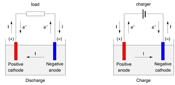
Electrochemical cells and batteries are categorised into two types.
1. Primary (non-rechargeable)
2. Secondary (rechargeable)
Primary batteries are non-rechargeable ones. This means they can’t be recharged with electricity. The secondary batteries are ideal for recharging.
The following are the different types of rechargeable batteries that are commonly used.
1. Lithium-ion(Li-ion)
2. Nickel Cadmium(Ni-Cd)
3. Nickel-Metal Hydride(Ni-MH)
4. Lead-Acid
Battery Sizes and rating :- The below figure shows the different battery size standards, their dimensions and their specific usage information.
Different battery Shapes :-
1. Cylindrical
2. Prismatic
3. Button cells
4. Pouch cells
1. Cylindrical Cells :-
Cylindrical cells are the most popular battery packs for both primary and secondary batteries and some of the easiest to manufacture. These cells have a pressure relief mechanism that enables them to withstand high internal pressure without deforming. Additional benefits include high mechanical stability, low cost, long life, and excellent cycling ability. These cells do not change their shape or size, so thermal management can be easily done with adequate spacing between the cells. The only drawback with these robust batteries is their weight and low packing density due to space cavities.

Cylindrical cells are highly reliable and typically come with a PTC switch that stops conducting current when a load draws excessive current, thereby offering short circuit protection. The switch returns to a conducting state once cooled. For mechanical safety, these cells use membrane seal or re-sealable vents. Some Li-ion cylindrical cells use charge interrupt device that disconnects the cell on exposure to unsafe mechanical pressure.
2. Prismatic Cells :-
Prismatic cells feature a flat rectangular design of these cells that allows maximum utilization of space. There is no standard size format for these cells, and their size varies with the manufacturers. They are commonly used in mobile phones, smartphones, notebook computers, and portable electronic gadgets, and are now the preferred choice in electric vehicles. The main drawbacks of these cells are poor thermal management, short life, and cost. They are prone to swelling due to gas build-up and may expand in size over a long time which presents safety hazards. They can also damage the device they are housed in, due to expansion and distortion.
3. Button Cells :-
Button cells or coin cells are used as small-size primary batteries intended for compact portable devices. These low-cost cells are seen in motherboards, wristwatches, portable medical equipment, and cordless telephones. Their major advantage is their compact size allowing them to be easily stacked in a tube to achieve higher voltages. Their main drawback is the lack of safety vents and high charging time. These cells are mainly used in compact devices or as a power backup for some part of a circuit. Coin cells are also used to maintain the clock in motherboards.

4. Pouch Cells :-
Pouch cells are the most flexible and lightweight of batteries. With sealed foil tabs from electrodes, these cells have a flexible bag-like enclosure that is designed to accommodate any swelling in the battery. Generally, small pouch cells may swell after a few hundred charge-discharge cycles, while large pouch cells may swell after several thousand cycles. This battery design is the most lightweight and allows maximum space utilization. Though designed for a light load, these cells can withstand high load currents and can be stacked side-by side to achieve higher voltages.
When pouch cells are manufactured, they are provided with a temporary gasbag. The gases that build up on the first charge escape to the gasbag, which is removed afterward. The pouch is then sealed and readied to supply. In subsequent charging cycles, a minimal amount of gas is produced, which may build up only after hundreds or thousands of cycles.
These cells have a higher energy density; however, these are quite expensive to manufacture. There is no standard size format for these cells — they come in a variety of sizes, and the size may vary with the manufacturers. Pouch cells are generally used in wearable electronics (like Bluetooth headphones, music players, and toys) and portable devices. There are also large pouch cells that are used in other applications such as UPS, ESS, etc.
Specifications of ANR26650M1-B cell :- The specifications are taken from data sheet which can be available at https://www.batteryspace.com/prod-specs/6610.pdf
The cell considered here is manufactured by A123 systems. A123’s high-performance Nanophosphate® lithium iron phosphate (LiFePO4) battery technology delivers high power and energy density combined with excellent safety performance and extensive life cycling in a lighter weight, more compact package. Our cells have low capacity loss and impedance growth over time as well as high usable energy over a wide state of charge (SOC) range, allowing our systems to meet end-of-life power and energy requirements with minimal pack oversizing.
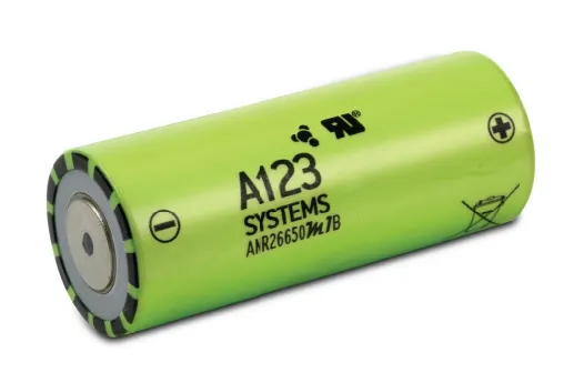
The battery parameters for the ANR26650M1-B cell taken from data sheet as shown below.
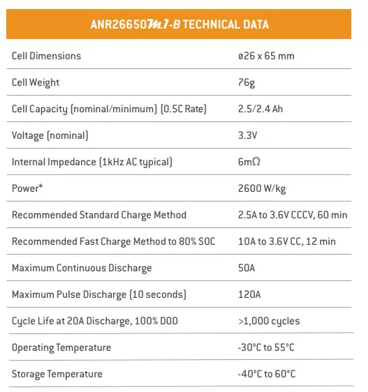
The below graphs represent the Constant power discharge characteristics at 23 degree centigrade temperature, and the variation of parameters of battery at 2.5C constant discharge current at various temperatures.
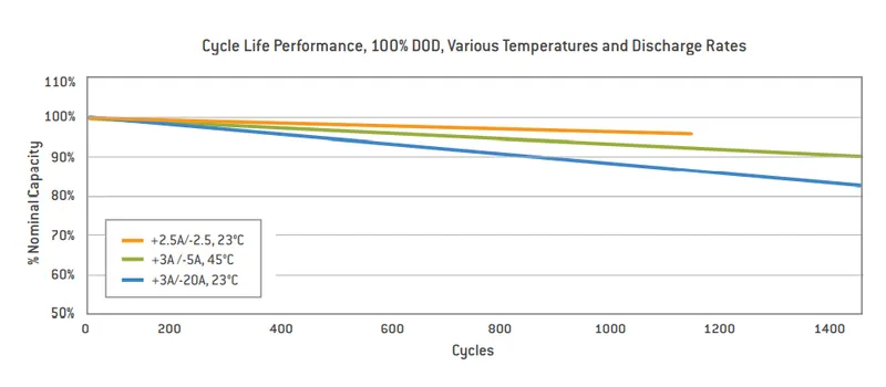
The below graph represents the variation of nominal capacity of battery performing cycles at different discharge rates and temperatures.
Battery Pack designing and construction :- The Designing and construction of a battery pack involves the following steps. The reference for this taken from skill lync's workshop video. https://www.youtube.com/watch?v=ltZk5Ihcw84
1. Determining No of cells for the required capacity of battery pack and dimensions.
2. Implementing a cooling system
3. Arrangement of sensors
4. Enclosure for cells
5. Implementing a BMS circuit for proper functioning of battery
6. Battery testing
1. Calcultion of No of cells required in series and parallel for 18 kWh battery pack :-
Let us assume the voltage of battery required be 800V.
From the above referred data sheet, The nominal voltage of each cell = 3.3 V and capacity of each cell = 2.5 Ah
A. No of cells required = total energy of battery pack/(Nominal Voltage*Capacity of each cell)
= 18*10^3/(3.3*2.5)
= 2182 cells
Total no of cells required is 2182 cells. With this no of cells, we can't configure series and parallel connections to get exact 18kWh battery. By calculating with trail and error, it is found that by using (total 2187) 243 cells in series with 9 parallel modules, we can get a battery pack of 802V with 18.042 kWh capacity.
Therefore cell configuration will be 243s9p. Battery pack capacity will be = No of parallel connections *Capacity of battery
= 9 * 2.5 =22.5 Ah
Space occupied by battery pack :-
Height of each cell is 65.15 mm and dia of each cell is 25.96 mm.
Therefore for 243s9p pack, the space occupied by battery pack with 10mm as clearance on all the sides is :-
Height of battery pack = 85.15 mm
Length of battery pack = (25.96 * 243)+20 = 6328mm
Width of battery pack = (25.96 * 9) + 20 = 253.64 mm
Total volume occupied by battery pack by considering clearence = 0.136 m^3.
Mass of each individual cell = 39.5 g
Mass of total battery pack = 2187*39.5/1000 = 86.4 kg
By considering battery enclosure and BMS weight, the weight of whole battery pack can go upto 90 kg.
2. Implementing a cooling system for battery pack :-
There are several methods to achieve cooling system for a battery pack. Some of then are illustrated below.
A. Phase Change Materials :-
Phase change material absorbs heat energy by changing state from solid to liquid. While changing phase, the material can absorb large amounts of heat with little change in temperature. Phase change material cooling systems can meet the cooling requirements of the battery pack, however, the volume change that occurs during a phase change restricts its application. Also, phase change material can only absorb heat generated, not transfer it away, which means that it won’t be able to reduce overall temperature as well as other systems.
Although not favorable for use in vehicles, phase change materials can be useful for improving thermal performance in buildings by reducing internal temperature fluctuations and reducing peak cooling loads.
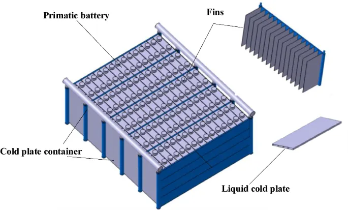
B. Cooling fins :-
Cooling fins increase surface area to increase the rate of heat transfer. Heat is transferred from the battery pack to the fin through conduction, and from the fin to the air through convection. Fins have high thermal conductivity and can achieve cooling goals, but they add a lot of additional weight to the pack. The use of fins has found a lot of success in electronics, and traditionally they have been used as an additional cooling system on internal combustion engine vehicles. Using fins to cool the electric car battery has fallen out of favor since the additional weight of the fins outweighs the cooling benefits.
C. Air cooling :-
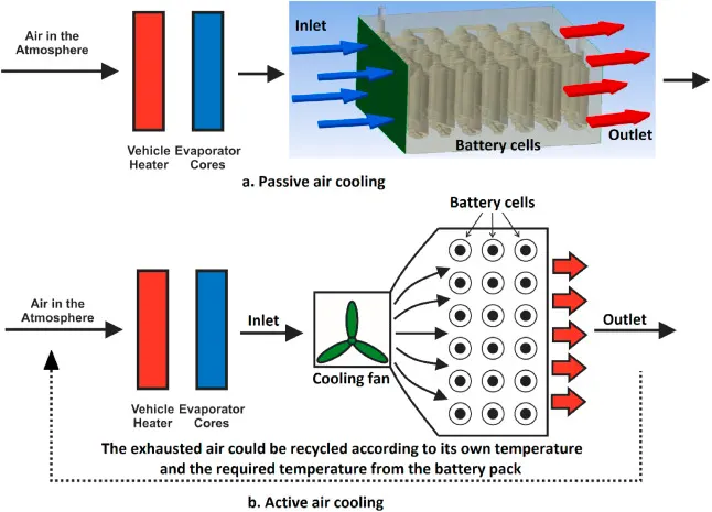
Air cooling uses the principle of convection to transfer heat away from the battery pack. As air runs over the surface, it will carry away the heat emitted by the pack. Air cooling is simple and easy, but not very efficient and relatively crude compared to liquid cooling. Air cooling is used in earlier versions of electric cars, such as the Nissan Leaf. As electric cars are now being used more commonly, safety issues have arisen with purely air-cooled battery packs, particularly in hot climates.
D. Liquid Cooling :- Car manufacturers, such as Tesla, insist that liquid cooling is the safest method. Liquid coolants have higher heat conductivity and heat capacity (ability to store heat in the form of energy in its bonds) than air, and therefore performs very effectively and own advantages like compact structure and ease of arrangement. Out of these options, liquid coolants will deliver the best performance for maintaining a battery pack in the correct temperature range and uniformity. Liquid cooling systems have their own share of safety issues related to leaking and disposal, as glycol can be dangerous for the environment if handled improperly.
3. Arrangement of battery sensors :-
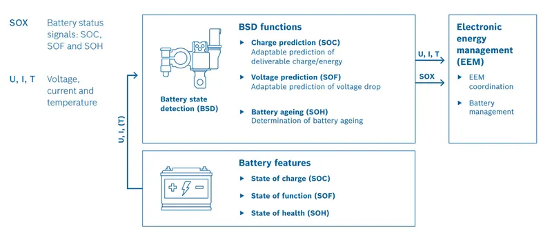
The electronic battery sensor (EBS) measures the current, voltage and temperature of 12V lead-acid batteries with great precision. The battery state detection algorithm (BSD) integrated into the EBS calculates the current and predicted state of charge and function of the battery from these base parameters and indicates battery aging effects. This information is passed on to a higher-level control unit, e.g. the electrical energy management (EEM) system. If needed, that system implements suitable measures to ensure the power supply to ancillaries that are important or critical to safety.
Moreover, it serves other purposes like maximizing battery life by avoiding deep discharge or supporting fuel- and CO2-saving technologies such as smart generator control, start/stop or recuperation. The sensor is also a key component in the design of safe and reliable vehicle electrical system topologies, thereby supporting the continuously increasing electrification and automation of vehicles as well as other applications, such as firmware over-the-air, predictive diagnostics, and predictive maintenance.
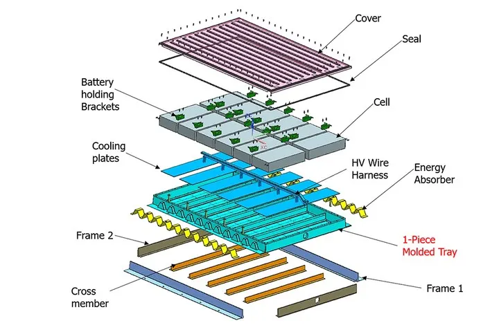
4. Design of cells enclosure :-
Lithium-ion Battery pack which is comprised of assembly of battery modules is the main source of power transmission for electric vehicles. During the actual operation of electric vehicle, the battery packs and its enclosure is subjected to harsh environmental conditions such as the external vibrations and shocks due to varying road slopes. This will result in stresses and deformations of different degrees. The vehicle safety heavily depends on on the safety of battery pack which in turn is dependent on its mechanical features, such as the ability to resist deformation and vibration shocks. In addition, lighter weight vehicle is preferred because it can increase the range of vehicle and the life cycle of a battery pack.
5. Implementing Battery Management system :-
Battery management system (BMS) is technology dedicated to the oversight of a battery pack, which is an assembly of battery cells, electrically organized in a row x column matrix configuration to enable delivery of targeted range of voltage and current for a duration of time against expected load scenarios. The oversight that a BMS provides usually includes:
1. Monitoring the battery
2. Providing battery protection
3. Estimating the battery’s operational state
4. Continually optimizing battery performance
5. Reporting operational status to external devices
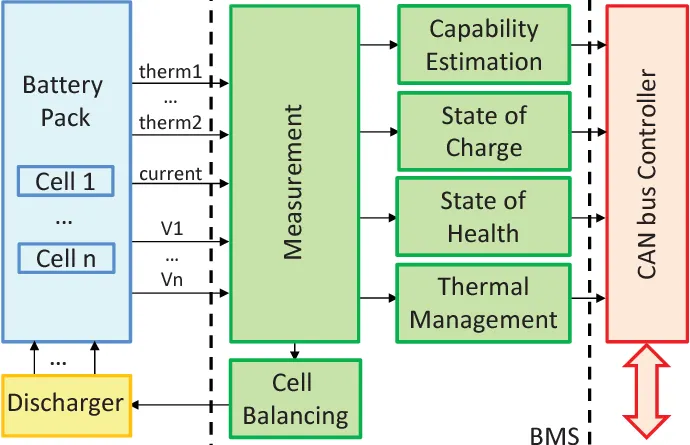
The BMS is implemented for battery pack to monitor real time status of the battery.
6. Battery testing :- Battery pack can be tested to evaluate Electrical performance, Thermal and mechanical performance. For more details on battery testing refer to https://www.mpoweruk.com/testing.htm
Result :- Hence the mechanical design of battery pack is done for 18 kWh capacity by using 2187 cells.
The space (Volume) of battery pack = 0.136m^3
Mass of battery pack = 90 kg approx
Energy density of the battery pack = 200 Wh/kg.