Modeling of Adaptive Cruise Control in MATLAB/SIMULINK
Aim :- To develop SIMULINK model to implement Adaptive Cruise Contol.
Objectives :-
- Developing Adaptive Cruise Control feature as per the Requirement Document using MATLAB Simulink.
- Follow all the MBD related processes: Requirement Tagging & Traceability, SLDD creation, Configuration Parameter changes, Model Advisor check & Code Generation.
- In Configuration Parameters: enable “Support Floating Numbers” under Code Generation settings.
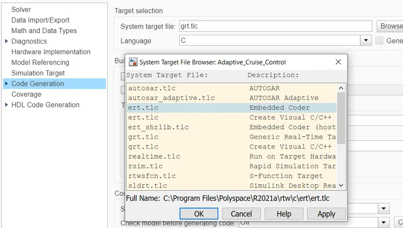
- Use Embedded Coder to generate the code.
- If choosing code generation, Storage class for Input signals: ImportedExtern; Storage class for Output signal: Export to File; Storage class for local signals: localizable; Storage class for calibration signals: Const.
- Choose sample time for all signals as 0.01s.
Requirements :- There are 3 requirements have to be followed and they are attatched within an Word Document for requirement tagging.
Requirement 1– Lead Vehicle:
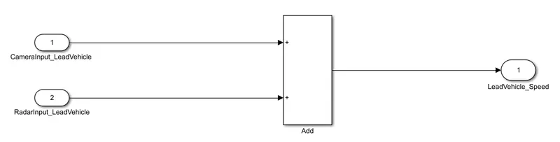
- Lead Vehicle is a vehicle which is driving in the road ahead of our drive vehicle. Two input signals (Signal Name: CameraInput_LeadVehicle & RadarInput_LeadVehicle).
- Ideally sensor fusion techniques will be deployed to process & analyze data from camera & radar. For complexity reasons, let’s not adapt to any such algorithms.
- We can simply add both the radar & camera inputs & the corresponding output is read as Speed profile output (Signal Name: LeadVehicle_Speed).
- Speed data of the lead vehicle is critical in implementing the Adaptive Cruise Control algorithm.
Requirement 2 – Drive Vehicle:
- Drive Vehicle is the vehicle driven by the user & this is the vehicle which has ACC algorithm in it.
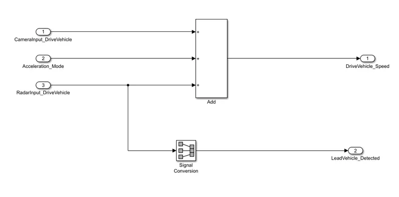
- Like the Lead Vehicle, Drive Vehicle algorithm also has 2 input signals (Signal Name: CameraInput_DriveVehicle, RadarInput_DriveVehicle) & one signal coming as an Input to this subsystem (Signal Name: Acceleration_Mode) – three inputs into this requirement in total.
- Like the above requirement, sensor fusion techniques will also be deployed here, for complexity reasons we are ignoring them.
- Two output signals come from this subsystem (Signal Name: DriveVehicle_Speed & LeadVehicle_Detected).
- Signal DriveVehicle_Speed is summation of three input signals mentioned above & LeadVehicle_Detected is renamed from Input Signal RadarInput_DriveVehicle by mere use of Signal Conversion block.
Requirement 3 – Adaptive Cruise Control Algorithm:
- Adaptive Cruise Control feature has 3 major modes of operation: OFF Mode, STANDBY Mode & ON Mode. This particular requirement has to be implemented as state machine logic in Simulink.
- The input signals to this state machine system are (Signal Name: Time_Gap, Set_Speed, Set_Gap, CruiseSwitch, SetSwitch).
- Also, the output signals (Signal Name: DriveVehicle_Speed & LeadVehicle_Detected) from requirement-2 is fed back as an input signal into this state machine block.
- Additionally, output signal (Signal Name: LeadVehicle_Speed) from requirement-1 is given as an input signal to this state machine block as well.
- Output from this subsystem is a signal (Signal Name: Acceleration_Mode) which governs the vehicular speed of the drive vehicle which automatically adjusts its speed & velocity to match the lead vehicle.
Requirement 3a – ACC OFF MODE state logic:
- This is the default state inside state machine logic. Output signal Acceleration_Mode is at value 0 in this state.
- This state is governed by input signal CruiseSwitch.
- If CruiseSwitch is equal to 1, state ACC STANDBY mode will get activated. If CruiseSwitch is equal to 0, state ACC OFF mode will get activated, from either ACC ON mode or ACC STANDBY mode
Requirement 3b – ACC STANDBY MODE state logic:
- This is the second activated state inside state machine logic. Output signal Acceleration_Mode is at value 1 in this state.
- This state is governed by both input signals CruiseSwitch & SetSwitch.
- If CruiseSwitch is equal to 1, state ACC STANDBY mode will get activated. If CruiseSwitch is equal to 0, state ACC OFF mode will get activated, from either ACC ON mode or ACC STANDBY mode
- If SetSwitch is equal to 1, state ACC ON mode will get activated. If SetSwitch is equal to 0, state ACC STANDBY mode will get activated.
Requirement 3c – ACC ON MODE state logic:
This state will be activated when input signal SetSwitch is equal to 1. There are 6 sub states to this state logic: They are:
- LeadVehicle_Detected_Follow (Default)
- LeadVehicle_Not_Detected
- LeadVehicle_Detected_Resume
- LeadVehicle_Not_Detected_Resume
- LeadVehicle_Speed_lessthan_Set_Speed
- LeadVehicle_Speed_equal_Set_Speed
Requirement 3c (i) – LeadVehicle_Detected_Follow (ACC ON MODE):
- This is the default sub state inside ACC ON MODE state. Output signal Acceleration_Mode is equal to 2.
- Condition to transit from LeadVehicle_Detected_Follow to LeadVehicle_Not_Detected; Input signal condition LeadVehicle_Detected == 0.
- Condition to transit from LeadVehicle_Detected_Follow to LeadVehicle_Speed_lessthan_Set_Speed; Input Signals condition (LeadVehicle_Detected == 1) && (LeadVehicle_Speed < Set_Speed) || (Time_Gap < Set_Gap).
Requirement 3c (ii) – LeadVehicle_Not_Detected (ACC ON MODE):
- Output signal Acceleration_Mode is equal to 1.
- Condition to transit from LeadVehicle_Not_Detected to LeadVehicle_Detected_Follow; Input signals condition [(LeadVehicle_Detected==1) && (DriveVehicle_Speed == Set_Speed) && (LeadVehicle_Speed >= Set_Speed) && (Time_Gap >= Set_Gap)]
- Condition to transit from LeadVehicle_Not_Detected to LeadVehicle_Speed_lessthan_Set_Speed; Input signals condition [(LeadVehicle_Detected == 1) && (LeadVehicle_Speed < Set_Speed) || (Time_Gap < Set_Gap)]
Requirement 3c (iii) – LeadVehicle_Detected_Resume (ACC ON MODE):
- Output signal Acceleration_Mode is equal to 3.
- Condition to transit from LeadVehicle_Detected_Resume to LeadVehicle_Detected_Follow; Input signals condition [(DriveVehicle_Speed == Set_Speed) && (LeadVehicle_Speed >= Set_Speed) && (Time_Gap >= Set_Gap)]
- Condition to transit from LeadVehicle_Detected_Resume to LeadVehicle_Not_Detected_Resume; Input signal condition LeadVehicle_Detected==0.
- Condition to transit from LeadVehicle_Detected_Resume to LeadVehicle_Speed_equal_Set_Speed; Input Signal condition [(DriveVehicle_Speed < Set_Speed) && (LeadVehicle_Speed > DriveVehicle_Speed) && (Time_Gap >= Set_Gap)]
Requirement 3c (iv) - LeadVehicle_Not_Detected_Resume (ACC ON MODE):
- Output signal Acceleration_Mode is equal to 1.
Requirement 3c (v) - LeadVehicle_Speed_lessthan_Set_Speed (ACC ON MODE):
- Output signal Acceleration_Mode is equal to 4.
- Condition to transit from LeadVehicle_Speed_lessthan_Set_Speed to LeadVehicle_Not_Detected; Input signal condition [(LeadVehicle_Detected == 0) && (DriveVehicle_Speed == Set_Speed)]
- Condition to transit from LeadVehicle_Speed_lessthan_Set_Speed to LeadVehicle_Speed_equal_Set_Speed; Input signals condition [((LeadVehicle_Speed*1.25>=DriveVehicle_Speed) && (LeadVehicle_Speed * 0.75<=DriveVehicle_Speed)) && (DriveVehicle_Speed < Set_Speed) && ((Time_Gap<=1.25*Set_Gap) && (Time_Gap >=0.75*Set_Gap))]
Requirement 3c (vi) - LeadVehicle_Speed_equal_Set_Speed (ACC ON MODE):
- Output signal Acceleration_Mode is equal to 5.
- Condition to transit from LeadVehicle_Speed_equal_Set_Speed to LeadVehicle_Not_Detected_Resume; Input signal conditions is [(LeadVehicle_Detected == 0) || (DriveVehicle_Speed <= Set_Speed)]
- Condition to transit from LeadVehicle_Speed_equal_Set_Speed to LeadVehicle_Detected_Resume; Input signal conditions [(DriveVehicle_Speed < Set_Speed) && (LeadVehicle_Speed > DriveVehicle_Speed) || (Time_Gap >= Set_Gap)]
- Condition to transit from LeadVehicle_Speed_equal_Set_Speed to LeadVehicle_Speed_lessthan_Set_Speed; Input signals conditions [(LeadVehicle_Speed
Adaptive Cruise Control :-
Adaptive cruise control (ACC) is an available cruise control advanced driver-assistance system for road vehicles that automatically adjusts the vehicle speed to maintain a safe distance from vehicles ahead. This is also known as Dynamic cruise control.
Control is based on sensor information from on-board sensors. Such systems may use a radar or laser sensor or a camera setup allowing the vehicle to brake when it detects the car is approaching another vehicle ahead, then accelerate when traffic allows it to. ACC technology is regarded as a key component of future generations of intelligent cars. The technology enhances passenger safety and convenience as well as increasing road capacity by maintaining optimal separation between vehicles and reducing driver errors.
Vehicles with autonomous cruise control are considered a Level 1 autonomous car, as defined by SAE International. When combined with another driver assist feature such as lane centering, the vehicle is considered a Level 2 autonomous car. Adaptive cruise control does not provide full autonomy: the system only provides some help to the driver, but does not drive the car by itself.
Model :- The preparatiion of final model involves different stages. The each stage of doing the model by satisfying the given requirements is shown below.
Stage 1 :- Creation of SLDD file
The SLDD file is created to define the variables and signals values to the model. The steps for creating SLDD file is as follows.
1. Go to Model Explorer > File > New > Click on Data Dictionary.
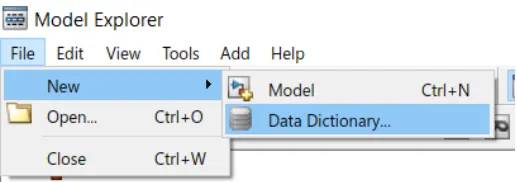
2. Assign a file name for data dictionary and save it in the current MATLAB folder.
3. Now give the input data to the data dictionary by adding Signals and parameters. After adding the Input values, the data dictionary is created. Save changes by right click on current data dictionary name.
4. Now the SLDD file is created with the required input values as shown. The Signals and Calibration data list is given in the question.
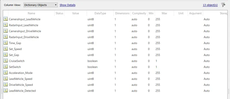
Stage 2 :- Link Data Dictionary to current model file
By doing this, the signals and constant values are automatically assigned to the input signals and blocks which we are created in Model. For this
1. Go to Modeling tab and Click on Link to Data Dictionary under Repositories.
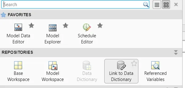
2. In the Dialogue box appeared, click on browse and select the created SLDD file. Uncheck the Enable model acces to base workspace, because the variables and signals are already defined in Model workspace as SLDD file. Click OK.
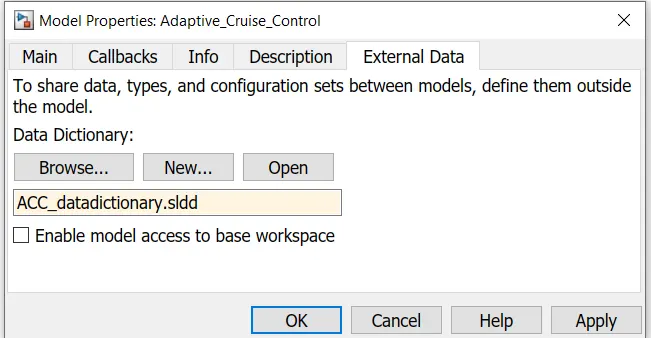
Stage 3 :- Creating Subsystems for requirements
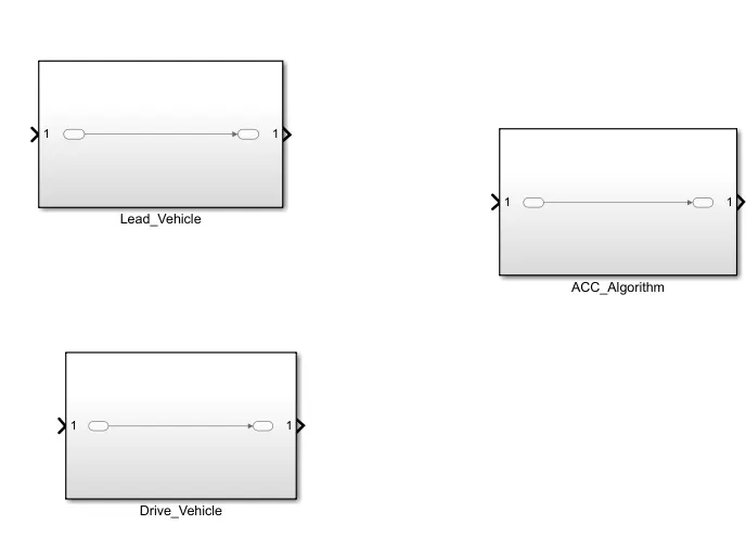
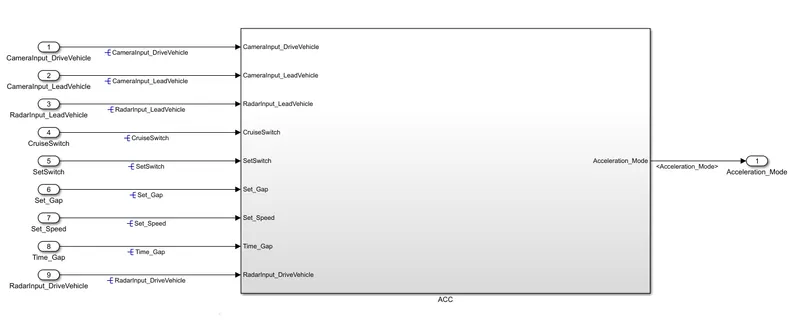
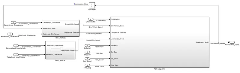
There are total 3 requirements to be fulfilled. For this create 3 new subsystems and name them as Lead_Vehicle, Drive_Vehicle and ACC_Algorithm. Under the each requirement subsystem, the requirement logic will be modeled.
Stage 4 :- Modelling of Requirement 1, Lead Vehicle
The model for Lead Vehicle is shown below. Add both the radar & camera inputs & the corresponding output is read as Speed profile output. The signals names are given as per the requirements provided.
Stage 5 :- Modelling of Requirement 2, Drive Vehicle
The model for Drive Vehicle is shown below. Signal DriveVehicle_Speed is summation of three input signals mentioned above & LeadVehicle_Detected is renamed from Input SignalRadarInput_DriveVehicle by mere use of Signal Conversion block.
Stage 6 :- Modelling of Requirement 3, Adapative Cruise Control Algorithm
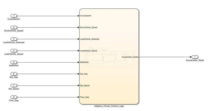
This requirement has several sub requirements. By following the requirements provided, the ACC algorithm is modelled as a stateflow chart as shown. All the names of states and transition conditional statements are also given in the project document.
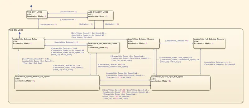
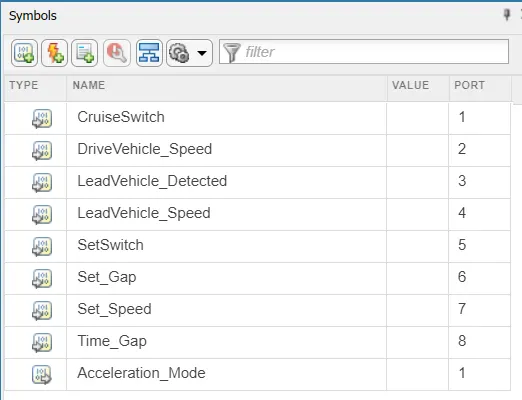
The inputs and outputs are defined in the symbol pane.
Stage 7 :- Changing data Types of Inputs and Outputs from ACC stateflow chart
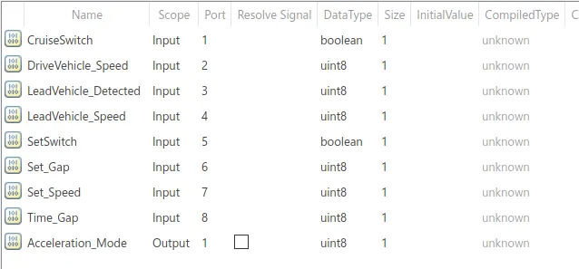
By going into model explorer, the DataType of Inputs and Outputs to ACC stateflow chart are changed as shown in the below.
Stage 8 :- Signal Resolving and Propagation
The resolving is done for the signal when it is present in the model for first time. After that the signal propagation is used where ever the signal to be send.
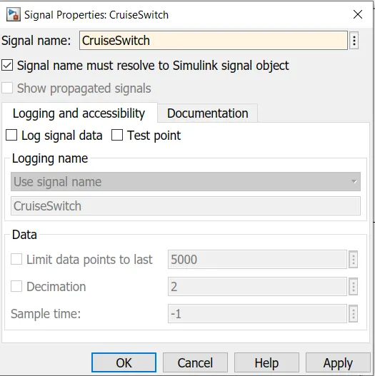
1. Right click on a signal Line, Click on properties. Then give signal name as matched in SLDD. Check Signal name must be resolve to Simulink signal object. Click ok. Then the signal will be resolved.
2. For signal propagation, name the signal line after resolved signal as "<>". Then automatically propagated signal will be appeared.
3. Do the resolving and propagation to all the signals in the model.
Stage 9 :- Running the model
The final SIMULINK model for ACC is shown below with the Resolved and propagated signals.
Step 10 :- Changing Model Settings
1. Change the solver settings to Fixed step discrete.

2. Under code generation select system target file browser as embedded coder.
Stage 11 :- Requirement Tagging
The requirement tagging is necessary for inorder to check what are the requirements for created substem in the project support documentation. For this requirement tagging the below steps are to be followed.
1. A word document is created with Necessary requirements and saved in the current/same matlab directory in which model is present.
2. Select the title of the requirement to be tagged lets say Requirement_1 and naviagate to simulink window as shown.
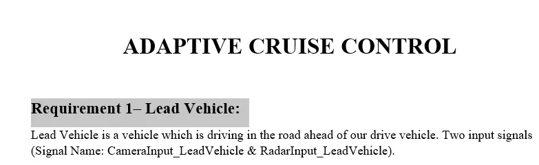
3. Right Click on Lead_Vehicle subsystem, click on 'Requirements' and 'Link to Selection in Word'. Then the tag is appear as "Requirement - 1-Lead Vehicle" shown below.
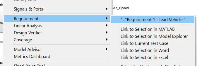
4. The same process should be done for Drive vehicle and ACC algorithm also.
Stage 12 :- Model Compliance check
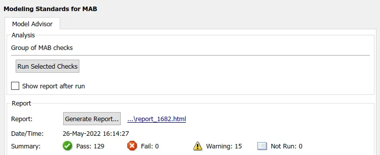
The model is checked with MAB guideliness from Model Advisor option in simulink. The errors can be rectified and warnings can be minimised with the help of suggestion in Advisor window. For performing this check follow the below steps.
1. Click on Model Advisor under Modeling Tab.
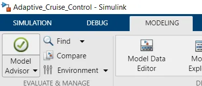
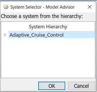
2. Select system Hierarchy and click ok.
3. In the model advisor window, select the Modeling Standards for MAB and Click on Run Selected Checks.
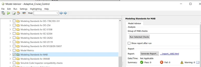
4. Try to reduce the warnings as much as possible by taking the suggested actions by Model Advisor.
5. After running the Checks, the no of warnings and errors are as shown.
Stage 13 :- Code Generation
The code is generated in Embedded C such that it is practically implemented at embedded sytems environment such as ACC module in car in case of this project. For code generation the following steps are to be followed.
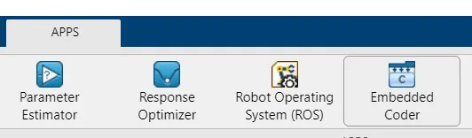
1. Go to Apps Tab and click on Embedded Coder.
2. Click on build.
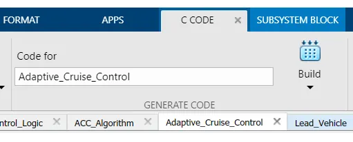
3. Then the code will be generated and the code file along with required supporting libraries are created in the current Matlab working folder.
Generated Code :-
/*
 * File: Adaptive_Cruise_Control.c
 *
 * Code generated for Simulink model 'Adaptive_Cruise_Control'.
 *
 * Model version                  : 1.26
 * Simulink Coder version         : 9.5 (R2021a) 14-Nov-2020
 * C/C++ source code generated on : Thu May 26 16:20:48 2022
 *
 * Target selection: ert.tlc
 * Embedded hardware selection: Intel->x86-64 (Windows64)
 * Code generation objectives: Unspecified
 * Validation result: Not run
 */

#include "Adaptive_Cruise_Control.h"
#include "Adaptive_Cruise_Control_private.h"

/* Named constants for Chart: '/Adaptive_Cruise_Control_Logic' */
#define Adaptive_Cr_IN_ACC_STANDBY_MODE ((uint8_T)3U)
#define Adaptive_Cru_IN_NO_ACTIVE_CHILD ((uint8_T)0U)
#define Adaptive_Cruise_IN_ACC_OFF_MODE ((uint8_T)1U)
#define Adaptive_Cruise__IN_ACC_ON_MODE ((uint8_T)2U)
#define IN_LeadVehicle_Detected_Follow ((uint8_T)1U)
#define IN_LeadVehicle_Detected_Resume ((uint8_T)2U)
#define IN_LeadVehicle_Not_Detected_Fol ((uint8_T)3U)
#define IN_LeadVehicle_Not_Detected_Res ((uint8_T)4U)
#define IN_LeadVehicle_Speed_equal_Set_ ((uint8_T)5U)
#define IN_LeadVehicle_Speed_lessthan_S ((uint8_T)6U)

/* Block states (default storage) */
DW_Adaptive_Cruise_Control_T Adaptive_Cruise_Control_DW;

/* External inputs (root inport signals with default storage) */
ExtU_Adaptive_Cruise_Control_T Adaptive_Cruise_Control_U;

/* External outputs (root outports fed by signals with default storage) */
ExtY_Adaptive_Cruise_Control_T Adaptive_Cruise_Control_Y;

/* Real-time model */
static RT_MODEL_Adaptive_Cruise_Cont_T Adaptive_Cruise_Control_M_;
RT_MODEL_Adaptive_Cruise_Cont_T *const Adaptive_Cruise_Control_M =
  &Adaptive_Cruise_Control_M_;
real_T rt_roundd_snf(real_T u)
{
  real_T y;
  if (fabs(u) < 4.503599627370496E+15) {
    if (u >= 0.5) {
      y = floor(u + 0.5);
    } else if (u > -0.5) {
      y = u * 0.0;
    } else {
      y = ceil(u - 0.5);
    }
  } else {
    y = u;
  }

  return y;
}

/* Model step function */
void Adaptive_Cruise_Control_step(void)
{
  int32_T tmp;
  int32_T tmp_0;
  uint8_T rtb_DriveVehicle_Speed;
  uint8_T rtb_LeadVehicle_Speed;
  uint8_T tmp_1;
  uint8_T tmp_2;

  /* Sum: '/Add' incorporates:
   *  Inport: '/CameraInput_DriveVehicle'
   *  Inport: '/RadarInput_DriveVehicle'
   *  UnitDelay: '/Unit Delay'
   */
  rtb_DriveVehicle_Speed = (uint8_T)((uint32_T)(uint8_T)((uint32_T)
    Adaptive_Cruise_Control_U.CameraInput_DriveVehicle +
    Adaptive_Cruise_Control_Y.Acceleration_Mode) +
    Adaptive_Cruise_Control_U.RadarInput_DriveVehicle);

  /* Sum: '/Add' incorporates:
   *  Inport: '/CameraInput_LeadVehicle'
   *  Inport: '/RadarInput_LeadVehicle'
   */
  rtb_LeadVehicle_Speed = (uint8_T)((uint32_T)
    Adaptive_Cruise_Control_U.CameraInput_LeadVehicle +
    Adaptive_Cruise_Control_U.RadarInput_LeadVehicle);

  /* Chart: '/Adaptive_Cruise_Control_Logic' incorporates:
   *  Inport: '/CruiseSwitch'
   *  Inport: '/RadarInput_DriveVehicle'
   *  Inport: '/SetSwitch'
   *  Inport: '/Set_Gap'
   *  Inport: '/Set_Speed'
   *  Inport: '/Time_Gap'
   *  UnitDelay: '/Unit Delay'
   */
  if (Adaptive_Cruise_Control_DW.is_active_c3_Adaptive_Cruise_Co == 0U) {
    Adaptive_Cruise_Control_DW.is_active_c3_Adaptive_Cruise_Co = 1U;
    Adaptive_Cruise_Control_DW.is_c3_Adaptive_Cruise_Control =
      Adaptive_Cruise_IN_ACC_OFF_MODE;
    Adaptive_Cruise_Control_Y.Acceleration_Mode = 0U;
  } else {
    switch (Adaptive_Cruise_Control_DW.is_c3_Adaptive_Cruise_Control) {
     case Adaptive_Cruise_IN_ACC_OFF_MODE:
      Adaptive_Cruise_Control_Y.Acceleration_Mode = 0U;
      if (Adaptive_Cruise_Control_U.CruiseSwitch) {
        Adaptive_Cruise_Control_DW.is_c3_Adaptive_Cruise_Control =
          Adaptive_Cr_IN_ACC_STANDBY_MODE;
        Adaptive_Cruise_Control_Y.Acceleration_Mode = 1U;
      }
      break;

     case Adaptive_Cruise__IN_ACC_ON_MODE:
      if (!Adaptive_Cruise_Control_U.CruiseSwitch) {
        Adaptive_Cruise_Control_DW.is_ACC_ON_MODE =
          Adaptive_Cru_IN_NO_ACTIVE_CHILD;
        Adaptive_Cruise_Control_DW.is_c3_Adaptive_Cruise_Control =
          Adaptive_Cruise_IN_ACC_OFF_MODE;
        Adaptive_Cruise_Control_Y.Acceleration_Mode = 0U;
      } else if (!Adaptive_Cruise_Control_U.SetSwitch) {
        Adaptive_Cruise_Control_DW.is_ACC_ON_MODE =
          Adaptive_Cru_IN_NO_ACTIVE_CHILD;
        Adaptive_Cruise_Control_DW.is_c3_Adaptive_Cruise_Control =
          Adaptive_Cr_IN_ACC_STANDBY_MODE;
        Adaptive_Cruise_Control_Y.Acceleration_Mode = 1U;
      } else {
        switch (Adaptive_Cruise_Control_DW.is_ACC_ON_MODE) {
         case IN_LeadVehicle_Detected_Follow:
          Adaptive_Cruise_Control_Y.Acceleration_Mode = 2U;
          if (Adaptive_Cruise_Control_U.RadarInput_DriveVehicle == 0) {
            Adaptive_Cruise_Control_DW.is_ACC_ON_MODE =
              IN_LeadVehicle_Not_Detected_Fol;
            Adaptive_Cruise_Control_Y.Acceleration_Mode = 1U;
          } else if (((Adaptive_Cruise_Control_U.RadarInput_DriveVehicle == 1) &&
                      (rtb_LeadVehicle_Speed <
                       Adaptive_Cruise_Control_U.Set_Speed)) ||
                     (Adaptive_Cruise_Control_U.Time_Gap <
                      Adaptive_Cruise_Control_U.Set_Gap)) {
            Adaptive_Cruise_Control_DW.is_ACC_ON_MODE =
              IN_LeadVehicle_Speed_lessthan_S;
            Adaptive_Cruise_Control_Y.Acceleration_Mode = 4U;
          }
          break;

         case IN_LeadVehicle_Detected_Resume:
          Adaptive_Cruise_Control_Y.Acceleration_Mode = 3U;
          if ((rtb_DriveVehicle_Speed == Adaptive_Cruise_Control_U.Set_Speed) &&
              (rtb_LeadVehicle_Speed >= Adaptive_Cruise_Control_U.Set_Speed) &&
              (Adaptive_Cruise_Control_U.Time_Gap >=
               Adaptive_Cruise_Control_U.Set_Gap)) {
            Adaptive_Cruise_Control_DW.is_ACC_ON_MODE =
              IN_LeadVehicle_Detected_Follow;
            Adaptive_Cruise_Control_Y.Acceleration_Mode = 2U;
          } else if (Adaptive_Cruise_Control_U.RadarInput_DriveVehicle == 0) {
            Adaptive_Cruise_Control_DW.is_ACC_ON_MODE =
              IN_LeadVehicle_Not_Detected_Res;
            Adaptive_Cruise_Control_Y.Acceleration_Mode = 1U;
          } else if ((rtb_DriveVehicle_Speed <
                      Adaptive_Cruise_Control_U.Set_Speed) &&
                     (rtb_LeadVehicle_Speed > rtb_DriveVehicle_Speed) &&
                     (Adaptive_Cruise_Control_U.Time_Gap >=
                      Adaptive_Cruise_Control_U.Set_Gap)) {
            Adaptive_Cruise_Control_DW.is_ACC_ON_MODE =
              IN_LeadVehicle_Speed_equal_Set_;
            Adaptive_Cruise_Control_Y.Acceleration_Mode = 5U;
          }
          break;

         case IN_LeadVehicle_Not_Detected_Fol:
          Adaptive_Cruise_Control_Y.Acceleration_Mode = 1U;
          if ((Adaptive_Cruise_Control_U.RadarInput_DriveVehicle == 1) &&
              (rtb_DriveVehicle_Speed == Adaptive_Cruise_Control_U.Set_Speed) &&
              (rtb_LeadVehicle_Speed >= Adaptive_Cruise_Control_U.Set_Speed) &&
              (Adaptive_Cruise_Control_U.Time_Gap >=
               Adaptive_Cruise_Control_U.Set_Gap)) {
            Adaptive_Cruise_Control_DW.is_ACC_ON_MODE =
              IN_LeadVehicle_Detected_Follow;
            Adaptive_Cruise_Control_Y.Acceleration_Mode = 2U;
          } else if (((Adaptive_Cruise_Control_U.RadarInput_DriveVehicle == 1) &&
                      (rtb_LeadVehicle_Speed <
                       Adaptive_Cruise_Control_U.Set_Speed)) ||
                     (Adaptive_Cruise_Control_U.Time_Gap <
                      Adaptive_Cruise_Control_U.Set_Gap)) {
            Adaptive_Cruise_Control_DW.is_ACC_ON_MODE =
              IN_LeadVehicle_Speed_lessthan_S;
            Adaptive_Cruise_Control_Y.Acceleration_Mode = 4U;
          }
          break;

         case IN_LeadVehicle_Not_Detected_Res:
          Adaptive_Cruise_Control_Y.Acceleration_Mode = 1U;
          break;

         case IN_LeadVehicle_Speed_equal_Set_:
          Adaptive_Cruise_Control_Y.Acceleration_Mode = 5U;
          if ((Adaptive_Cruise_Control_U.RadarInput_DriveVehicle == 0) ||
              (rtb_DriveVehicle_Speed <= Adaptive_Cruise_Control_U.Set_Speed)) {
            Adaptive_Cruise_Control_DW.is_ACC_ON_MODE =
              IN_LeadVehicle_Not_Detected_Res;
            Adaptive_Cruise_Control_Y.Acceleration_Mode = 1U;
          } else if (((rtb_DriveVehicle_Speed <
                       Adaptive_Cruise_Control_U.Set_Speed) &&
                      (rtb_LeadVehicle_Speed > rtb_DriveVehicle_Speed)) ||
                     (Adaptive_Cruise_Control_U.Time_Gap >=
                      Adaptive_Cruise_Control_U.Set_Gap)) {
            Adaptive_Cruise_Control_DW.is_ACC_ON_MODE =
              IN_LeadVehicle_Detected_Resume;
            Adaptive_Cruise_Control_Y.Acceleration_Mode = 3U;
          } else if (((rtb_LeadVehicle_Speed <
                       Adaptive_Cruise_Control_U.Set_Speed) &&
                      (rtb_LeadVehicle_Speed < rtb_DriveVehicle_Speed)) ||
                     ((int32_T)rt_roundd_snf(0.75 * (real_T)
                       Adaptive_Cruise_Control_U.Set_Gap) ==
                      Adaptive_Cruise_Control_U.Time_Gap)) {
            Adaptive_Cruise_Control_DW.is_ACC_ON_MODE =
              IN_LeadVehicle_Speed_lessthan_S;
            Adaptive_Cruise_Control_Y.Acceleration_Mode = 4U;
          }
          break;

         default:
          /* case IN_LeadVehicle_Speed_lessthan_Set_Speed: */
          Adaptive_Cruise_Control_Y.Acceleration_Mode = 4U;
          if ((Adaptive_Cruise_Control_U.RadarInput_DriveVehicle == 0) &&
              (rtb_DriveVehicle_Speed == Adaptive_Cruise_Control_U.Set_Speed)) {
            Adaptive_Cruise_Control_DW.is_ACC_ON_MODE =
              IN_LeadVehicle_Not_Detected_Fol;
            Adaptive_Cruise_Control_Y.Acceleration_Mode = 1U;
          } else {
            tmp = (int32_T)rt_roundd_snf((real_T)rtb_LeadVehicle_Speed * 1.25);
            tmp_0 = (int32_T)rt_roundd_snf(1.25 * (real_T)
              Adaptive_Cruise_Control_U.Set_Gap);
            if (tmp < 256) {
              tmp_1 = (uint8_T)tmp;
            } else {
              tmp_1 = MAX_uint8_T;
            }

            if (tmp_0 < 256) {
              tmp_2 = (uint8_T)tmp_0;
            } else {
              tmp_2 = MAX_uint8_T;
            }

            if ((tmp_1 >= rtb_DriveVehicle_Speed) && ((int32_T)rt_roundd_snf
                 ((real_T)rtb_LeadVehicle_Speed * 0.75) <=
                 rtb_DriveVehicle_Speed) && (rtb_DriveVehicle_Speed <
                 Adaptive_Cruise_Control_U.Set_Speed) &&
                (Adaptive_Cruise_Control_U.Time_Gap <= tmp_2) &&
                (Adaptive_Cruise_Control_U.Time_Gap >= (int32_T)rt_roundd_snf
                 (0.75 * (real_T)Adaptive_Cruise_Control_U.Set_Gap))) {
              Adaptive_Cruise_Control_DW.is_ACC_ON_MODE =
                IN_LeadVehicle_Speed_equal_Set_;
              Adaptive_Cruise_Control_Y.Acceleration_Mode = 5U;
            }
          }
          break;
        }
      }
      break;

     default:
      /* case IN_ACC_STANDBY_MODE: */
      Adaptive_Cruise_Control_Y.Acceleration_Mode = 1U;
      if (!Adaptive_Cruise_Control_U.CruiseSwitch) {
        Adaptive_Cruise_Control_DW.is_c3_Adaptive_Cruise_Control =
          Adaptive_Cruise_IN_ACC_OFF_MODE;
        Adaptive_Cruise_Control_Y.Acceleration_Mode = 0U;
      } else if (Adaptive_Cruise_Control_U.SetSwitch) {
        Adaptive_Cruise_Control_DW.is_c3_Adaptive_Cruise_Control =
          Adaptive_Cruise__IN_ACC_ON_MODE;
        Adaptive_Cruise_Control_DW.is_ACC_ON_MODE =
          IN_LeadVehicle_Detected_Follow;
        Adaptive_Cruise_Control_Y.Acceleration_Mode = 2U;
      }
      break;
    }
  }

  /* End of Chart: '/Adaptive_Cruise_Control_Logic' */
}

/* Model initialize function */
void Adaptive_Cruise_Control_initialize(void)
{
  /* (no initialization code required) */
}

/* Model terminate function */
void Adaptive_Cruise_Control_terminate(void)
{
  /* (no terminate code required) */
}

/*
 * File trailer for generated code.
 *
 * [EOF]
 */
Result :- Hence, the Adapative Cruise Control is modeled in Simulink by satisfying the given objectives and requirements. The code for the model is generated by using Embedded Coder.