Design of an Electric Vehicle
Aim :- To design a system level configuration electric vehicle.
Theory :- An electric vehicle (EV) is an automotive vehicle that uses one or more electric motors for propulsion. It can be powered by a collector system, with electricity from extravehicular sources, or it can be powered autonomously by a battery (sometimes charged by solar panels, or by converting fuel to electricity using fuel cells or a generator). EVs include, but are not limited to, road and rail vehicles, surface and underwater vessels, electric aircraft and electric spacecraft.
Some of the examples of Electric Vehicles are Tesla Model X, Audi E-tron, Porsche Tycan, Tata Nexon etc.
Advantages of Electric Vehicles :-
1. Reduced emissions,
2. No noise pollution,
3. Higher efficiency,
4. Less operating and maintainance cost.
Disadvantages :-
1. Range anxiety
2. Maintainance may be low but repair cost will be high because in some cases whole control module must be replaced.
3. Slower charging times
Modelling :- The below figure shows model for system level configuration of electric vehicle operated with DC motor. The assumed parameters are shown individually.
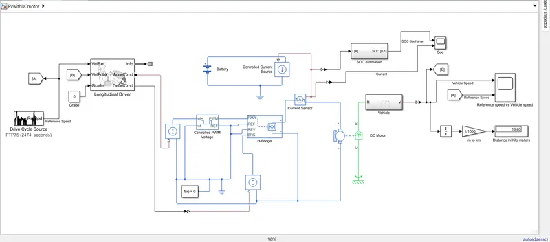
The subsystems are modelled as shown:-
Vehicle:-
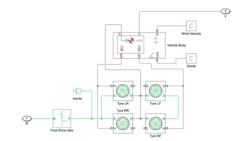
The tyre used is tyre magic formula. The vehicle body and tyre parameters are considered by default. The gear box is also used to muiltiply the speed inorder to get required torque output. The wind velocity is provided as 5 m/s and no grade is provided.
Drive Cycle:-
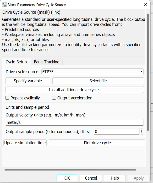
The FTP-75 drive cycle is used and the units of speed is given in m/sec. The reference speed is attached to scope using goto and from blocks.
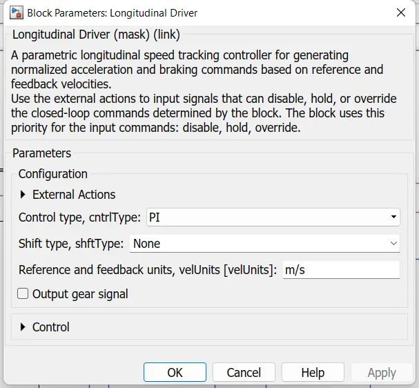
Longitudinal Driver :- It is a speed tracking driver for generating acceleration and braking commands with reference to input speed.
Controlled PWM Voltage :-
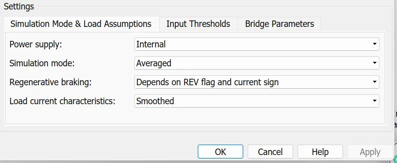
This block creates a Pulse-Width Modulated (PWM) voltage across the PWM and REF ports. The output voltage is zero when the pulse is low, and is equal to the Output voltage amplitude parameter when high. Duty cycle is set by the input value. The frequency given is 4000Hz and simulation mode is averaged.
H-bridge :-
The block can be driven by the Controlled PWM Voltage block in PWM or Averaged mode. In PWM mode, the motor is powered if the PWM port voltage is above the Enable threshold voltage. In Averaged mode, the PWM port voltage divided by the PWM signal amplitude parameter defines the ratio of the on-time to the PWM period. Using this ratio and assumptions about the load, the block applies an average voltage to the load that achieves the correct average load current.
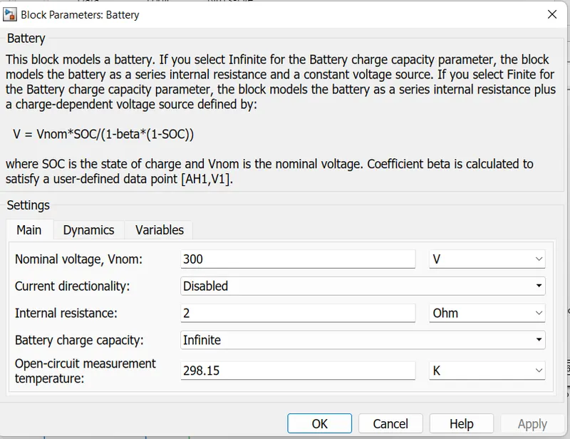
Battery :- The battery is taken and considered the rating as per motor and H-bridge ratings.
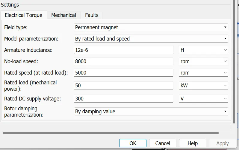
DC Motor:- The DC motor is used to propell the vehicle. The parameters and rating of motor is shown below.
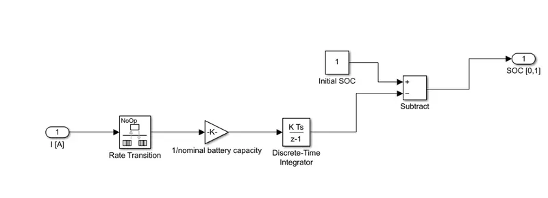
SOC estimation :- The soc estimation subsystem is shown below. The discharged SOC is subtracted from initial SOC to get the Real time SOC.
Results and Observations :-
The simulation is done for 2474 seconds as FTP 75 cycle time is 2474 seconds. The results are obtained as follows.
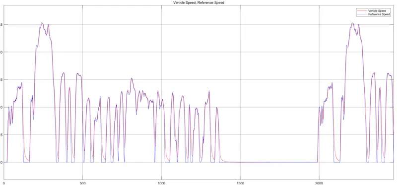
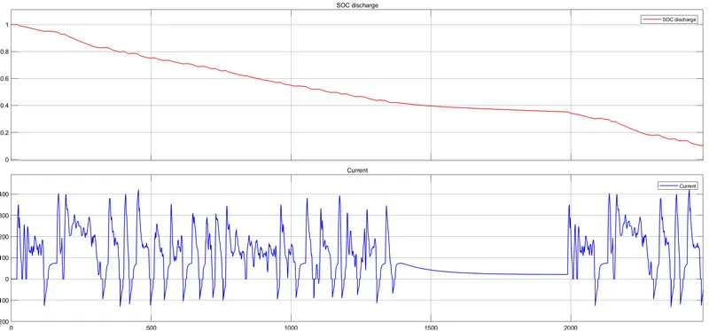
From the above results the vehicle traced the given Drive cycle and the car travelled a distance of 18.65 km which is nearly same as FTP distance 17.76 km.