Foundation Design using SAFE
AIM : Design of Foundation using SAFE V20.
INTRODUCTION:
- CSI SAFE (Slab Analysis by the Finite Element method) is the best tool for designing concrete slabs and foundations.
- SAFE provides easiness to engineer towards the safe design of structures with powerful tools like draw, analyze, design and detailing, etc.
- Laying out models is the quick and efficient way with the user-friendly drawing tools or users can import models from AutoCAD or loading conditions from the other software like CSI ETABS and CSI SAP2000.
PROCEDURE:
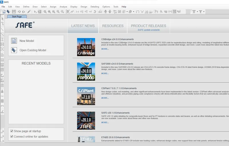
- Open the SAFE Application
- Select New Model
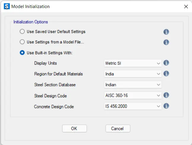
- Select the Units and Design codes.
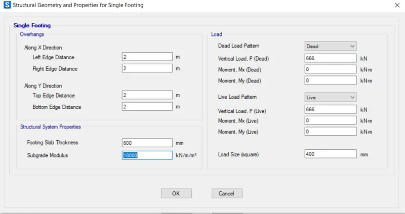
- Single Footing was selected next
Subgrade Modulus = `frac{F.O.SxxS.B.C}{(SET TELEMENT)`
Where, FOS for soil = 3
S.B.C = 150 KN/m^2
Settelement for Isolated footing = 25 mm
Hence ; Subgrade modulus = 18000 KN/m/m^2
The compression axial load for the load combination (1.5DL + 1.5LL) is 2000KN.
Unfactored load = `2000/1.5` = 1333.6 KN
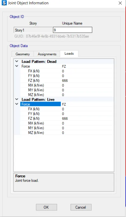
Live Load = `1333.6/2` = 666.5 KN
Dead load = `1333.6/2` = 666.5 KN
Footing thickness 600mm
Column Load Size = 400 x 400 mm
Give data for the footings as shown in figure below.
Define Materials
Go to the Define Tab and select Material property.
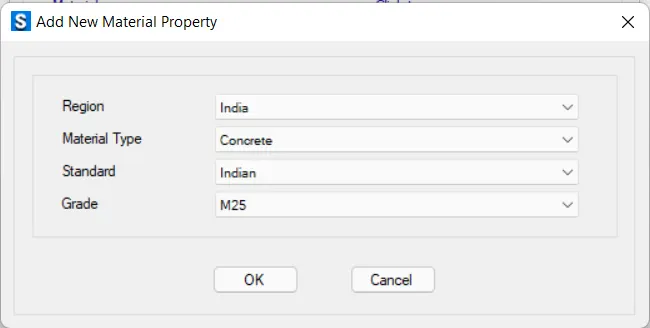
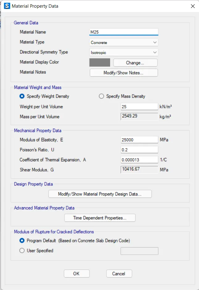
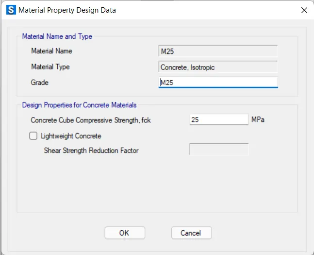
- Add M25 Concrete
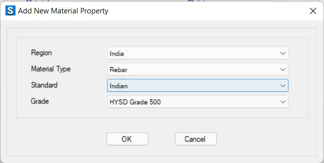
- Add new property as Rebar.
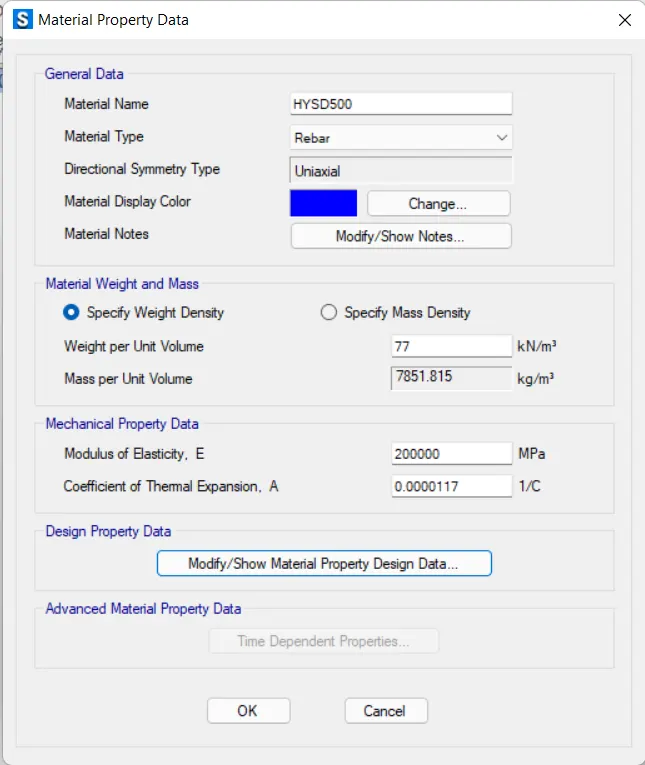
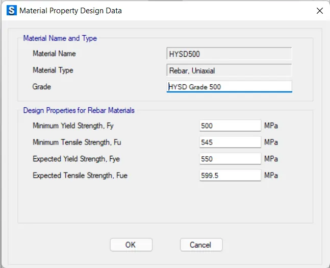
Define Section Property
- Next, Define Section Property
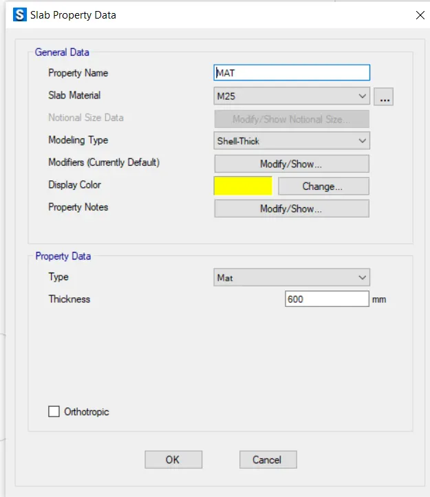
- Go to slab property.
- Add Mat > Thick shell < Mat type < 600 mm thickness
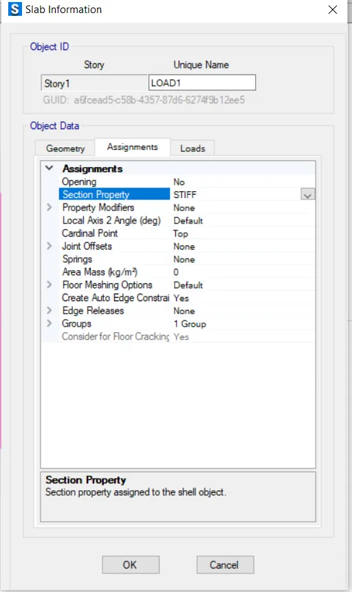
- Add next STIFF property.
- Change the type as Stiff.
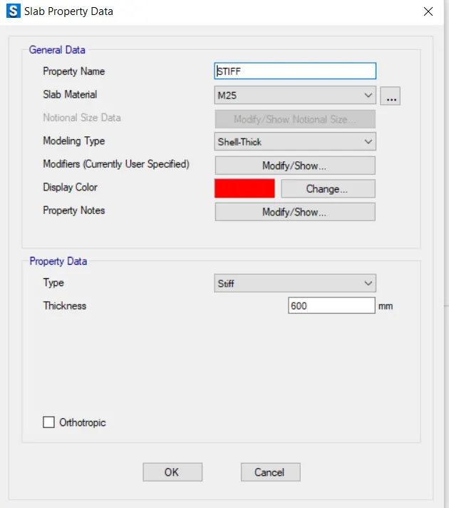
- Now right click on Slab/floor and change the Section Property as Mat.
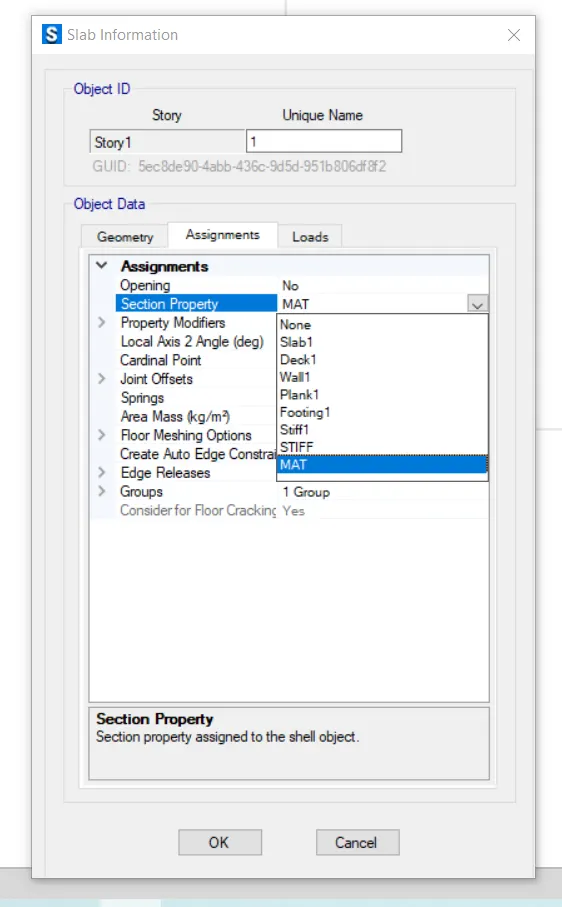
- Now Right Click on Column and change the Section Property as STIFF.
Check the Forces Applied by Right click on Column joints.
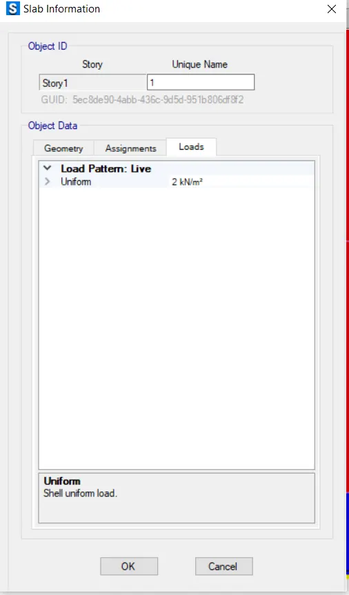
- Apply Live load of 2KN/m on the Footing/Slab
- Select the slab and assign the uniform load of 2 KN.
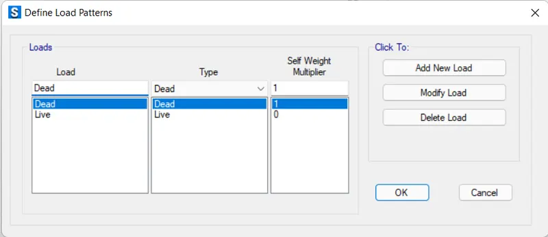
Check the Load Patterns
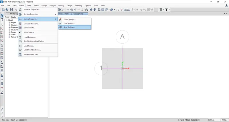
- Go to Define Tab then Spring properties.
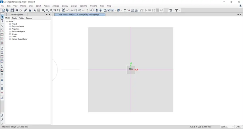
- Click on Area Spring and change the name of (Aspr) as Soil.
Define Load Combination
- Go to Define Tab and select Load combination
- Add New Combo as SLS
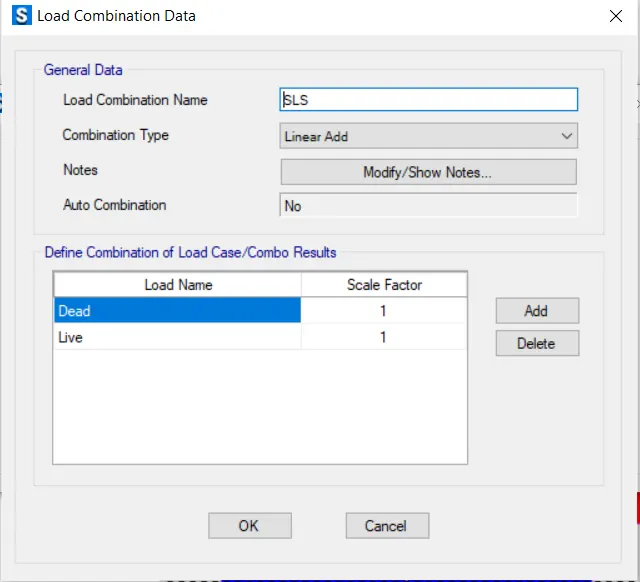
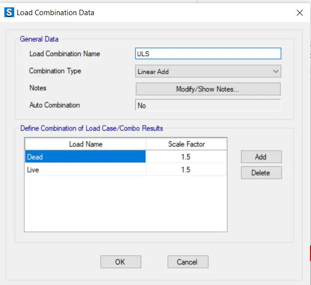
- Add new combo as ULS.
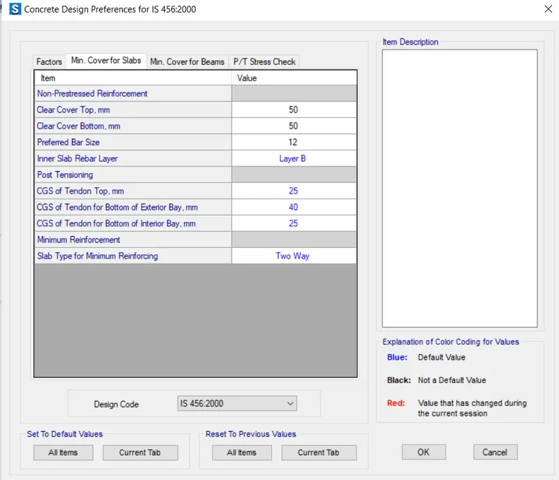
- Click on the Icon (Concrete slab/Beam Design) and check the prefences like cover, bar dia etc.
- Agian Click on the Icon (Concrete slab/Beam Design) and go the Design Load Combination.
- Add the Combination.
Add Design Strips
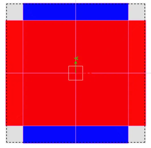
- Go to the edit tab and select Add/Edit Design Strips.
- Or Add Manually Design Strips from the Draw Design Strips Tool.
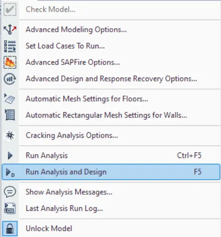
Check the Model and Analyse.

Check the Displacements :
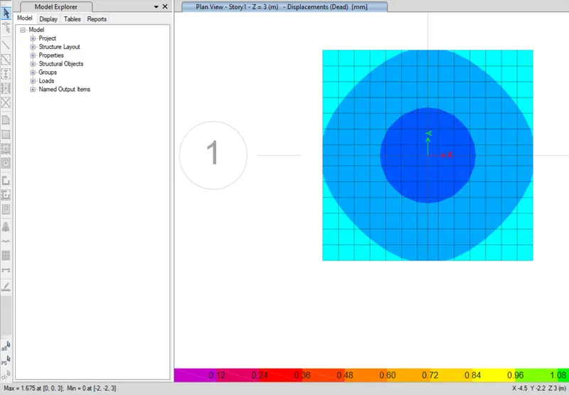
Max Disp = 1.675 @(0,0,3)
Check the Soil Pressure :
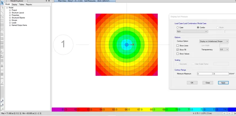
Max Soil Pressure = 71.486 @(0,0.2,3) in SLS condition.
Checking Punching Shear
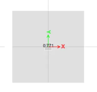
Here Punching shear is 0.771 < 1 ,henc ok.
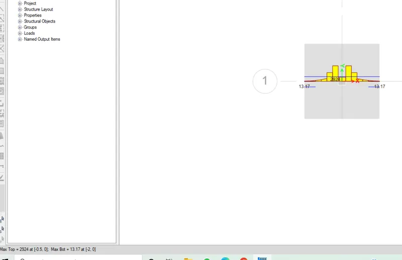
Check Strip Slab Design.
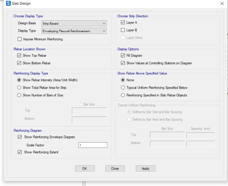
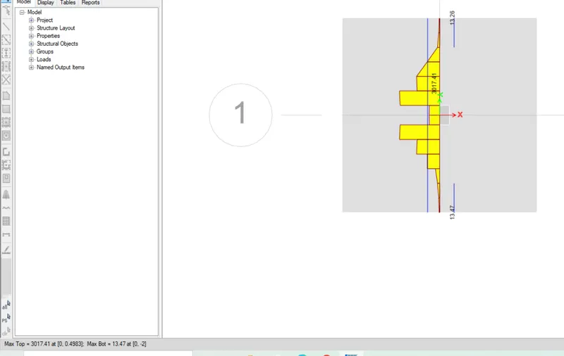
Now check on Layer B
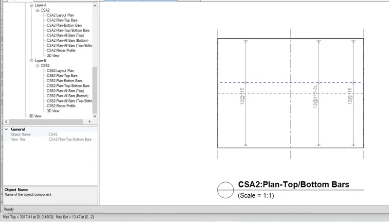
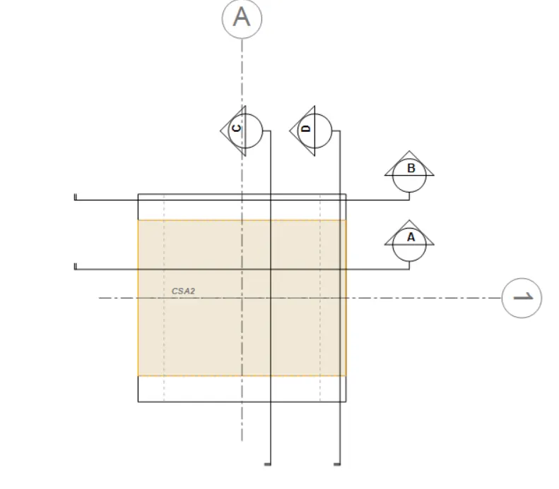
RESULT:
Hence, The Isolated Footing was designed and analyzed using SAFE successfully. The results of each drawing drawn in SAFE are attached.
A column of size 600x600 carrying an unfactored gravity load (DL+LL) of 1175 KN is to be supported on a pile cap, which ultimately transfers the load to the piles underneath. Piles of 16 meters length and 500 mm diameter are to be used. Each pile has a load-carrying capacity of 200 KN. Model, analyze and design the pile cap on SAFE to evaluate the following:
- Pile group to be used
- Depth of pile cap
- Longitudinal steel on top and bottom face in both directions
AIM:
- To model analyze and design the pile cap on SAFE.
- To evaluate the following:
- Pile group to be used
- Depth of pile cap
- Longitudinal steel on top and bottom face in both directions
INTRODUCTION :
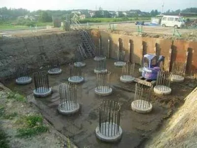
- Pile foundations are deep foundations.
- They are formed by long, slender, columnar elements typically made from steel or reinforced concrete, or sometimes timber.
- A foundation is described as 'piled' when its depth is more than three times its breadth.
PROCEDURE:
Given Data:
Column Size:- 600X600
Unfactored load:- 1175KN
Pile length:- 16m
Pile Diameter:- 500mm
Load carrying Capacity:- 200KN
Calculations:
Number of pilers:- `frac{1175xx1.1}{200} = 6.4`
But we take 8 piles for the symmetric load distribution.
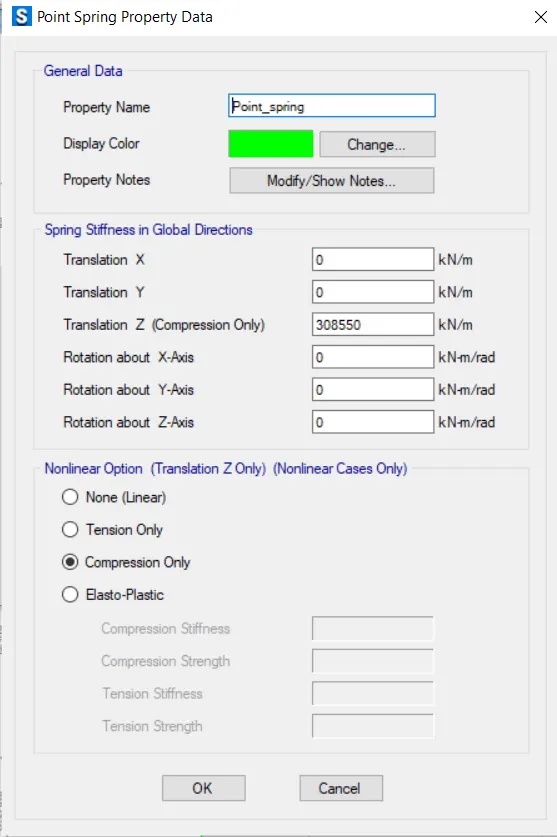
Spring Constant:- `A xx E/L`
where E is:- `5000sqrt(Fck)`
Area (A) is:- `pi/4xxd^2`
Pile Length, L is:- 16000mm
Spring Constant:- 306800 KN/m
Edge spacing is taken as 300mm.
- Open the SAFE Application.
- Select New Model
- Followed by input settings.
- Units were selected as Metric and code IS:456-2000.
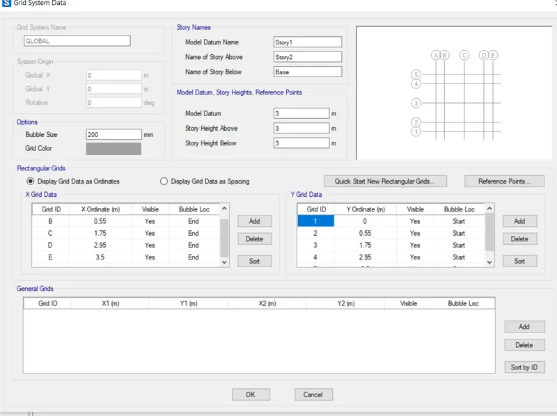
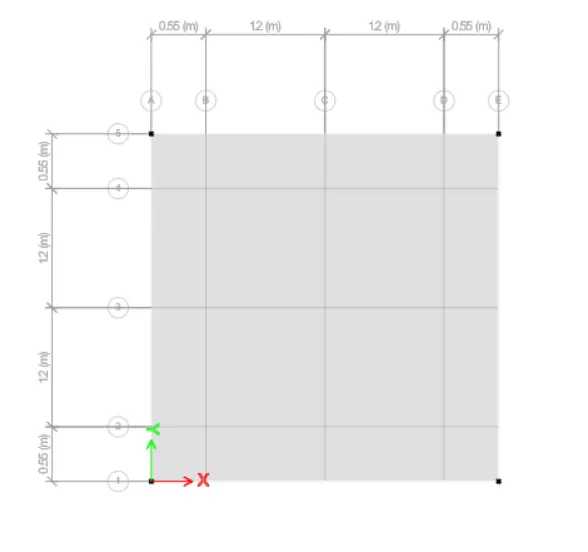
- Add the grid in X and Y ordinates.
Define Material Property
- Go to Define Tab and select Material Property.
- Add New Property.
- M25 grade of concrete
- Add New Property as Rebar
Define Section Properties
- Go to the Define TAb and Select Section Property
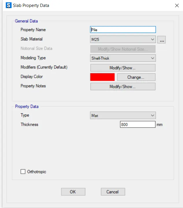
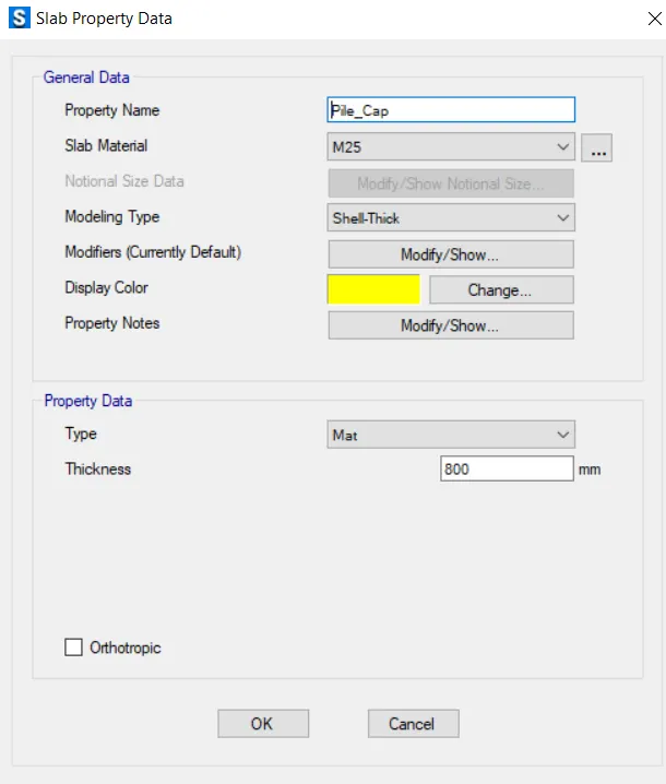
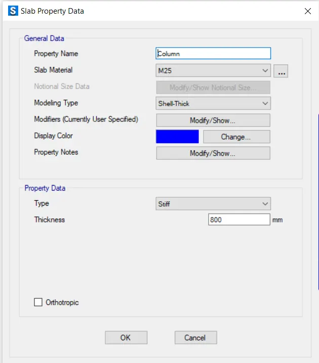
- Add New Section PRoperty as Pile (As Mat material), Pile_Cap (As Mat material) and Column (as STIFF material)
Draw the Floor/Slabs
- Go to the Slab/Floor tool and select property as slab as Pile_Cap.
- Drag diagonally and draw slab/floor.
Draw points
- Go to the Draw tab and select Draw Joints Objects.
- Now the Draw the Joints where i want.
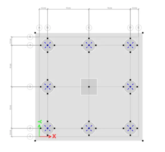
- Now Draw the Pile
- Go to the Quick draw area around point Tool.
- Select Shape as Circular and Property as Pile.
- Draw piles on all the joints except centre joints.
- Now Draw Column in centre.
- Again select quick draw area around point and shape as rectangle and Property name as Column.
Define Point Spring
- Go to Define Property and select Spring Property.
- Click on Point Spring Property and change the Data
Assign the Point Spring.
- Select the all Piles joints and go to assign and select Joint Assignment.
- Select point Spring to assign it.
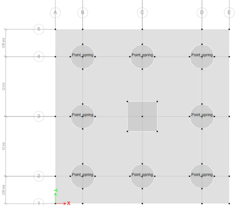
Assign Point load:
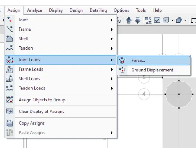
- Select middele Joints of Column and apply Load by assigning Tab > Joints Load
- Next, Add Dead and live load of 587.5KN
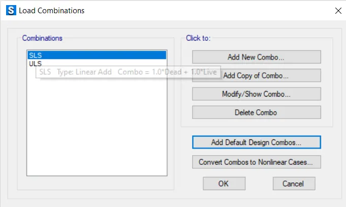
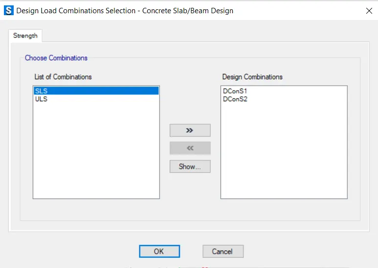
Define Load Combination
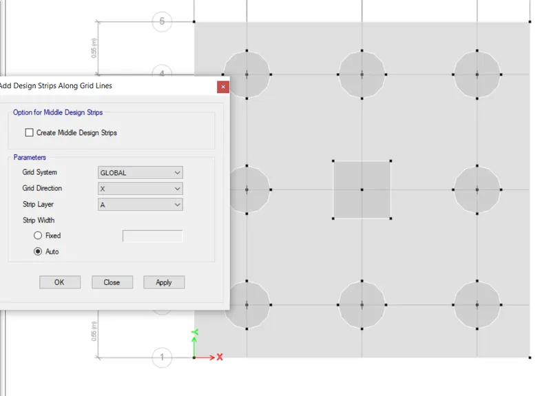
Add Design Strips :
- Go to edit Tab and select Add Design Strips Along X-A and Y-B.
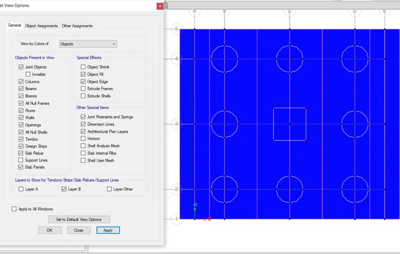
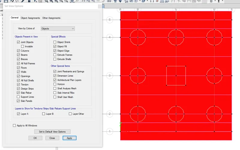
Add Design Load Load Combination.
Now Run the Analysis and Check the Results
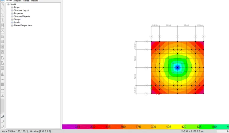
Max Displacement = 0.524 @ (1.75,1.75,3)
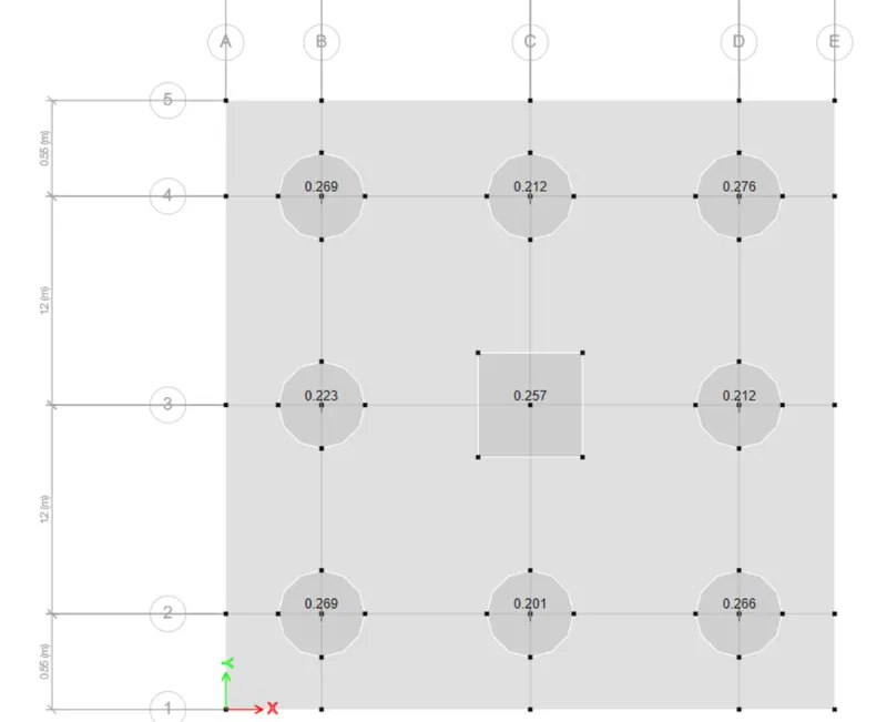
Punching shear is less than 1, Hence; ok.
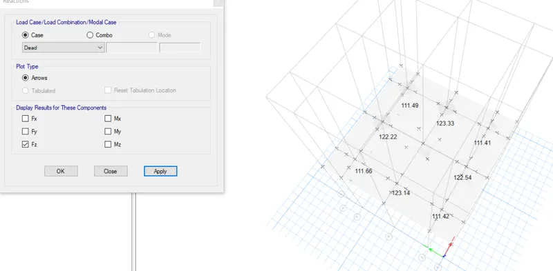
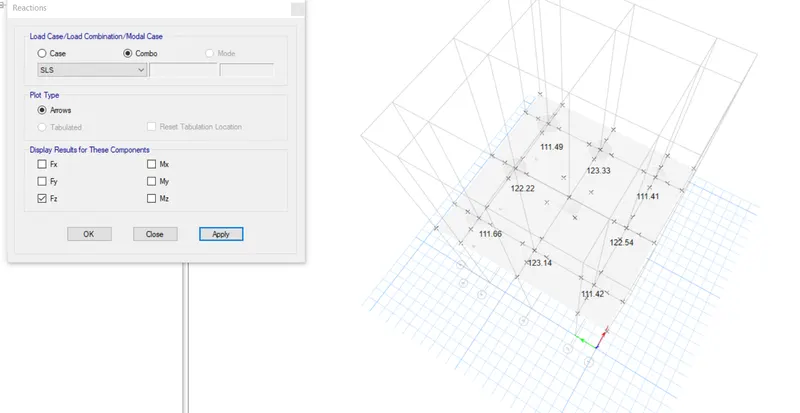
Support Reactions( Dead + Live) = Max 123.33 >200 hence ok.
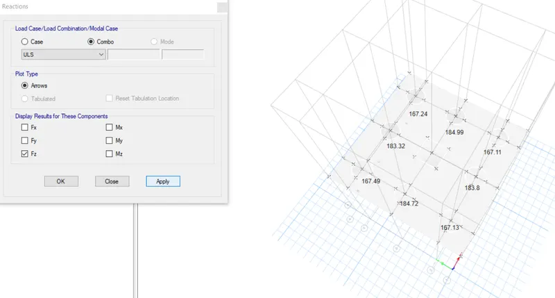
Show Slab Design
Reinforcement Detail
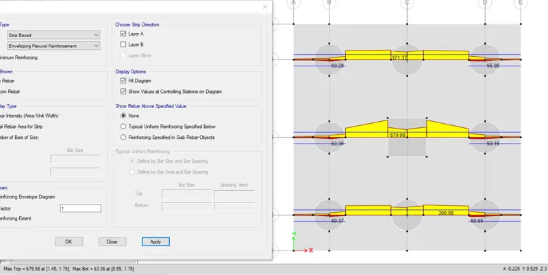
Maxm in X-A = 679.98 mm^2
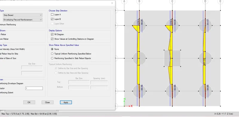
Maxm in Y-B = 1270 mm^2
RESULT:
Hence, Completed the design of the pile cap foundation using SAFE Software. The results of each drawing drawn in SAFE are attached.