1) Aim :
Compare the three alternatives, taking into account the restraint of floor shrinkage, the lateral stiffness and the torsional one with respect to the vertical axis, the vertical reinforcement required for the same total flexural capacity at the base, the static eccentricity, the system’s redundancy, foundation systems, architectural constraints.
a) Restraint of floor shrinkage
| Case A |
Case B |
Case C |
- It has good restraint against floor shrinkage because the shear walls are placed at the corners.
- These walls at the corners will tightly hold the floor which control the shrinkage.
|
- The shear walls are placed along the edges of the floor hence this wall will provide better stability to the floor near it but the corner portions there is chance to shrinkage.
|
- The floor is not enclosed with shear walls in both principal directions hence the floor will have a high shrinkage effect.
|
b) Lateral stiffness
| Case A |
Case B |
Case C |
- The edges have not any support hence during the earthquake excitation, the forces tend to act along the edges of the floor, this placement of shear walls will have the least stability and hence the lateral stiffness will also be less.
|
- The shear walls are placed along the edges which is the same direction of earthquake excitation, the structure will have more stability and thus possess high stiffness in both the principal directions.
|
- In the X-direction as there are two shear walls at both edges of the floor hence has more Stiffness.
- Whereas in the Y-direction, there is only one shear wall which leads to the concentration of seismic force in that wall and reduces the lateral stiffness in that direction.
|
c) Tortional with vertical axis
| Case A |
Case B |
Case C |
- The plan is symmetric, hence there is no eccentricity, so the centre of mass and centre of stiffness coincide, so it is less prone to torsion.
|
- The plan is symmetric, hence there is no eccentricity, so the centre of mass and centre of stiffness coincide, so it is less prone to torsion.
|
- In this Plan, the shear wall placement is unsymmetrical along the Y-direction, So the centre of mass and centre of stiffness will not coincide. Thus this arrangement will experience torsion during the earthquake.
|
d) The vertical reinforcement required
| Case A |
Case B |
Case C |
- The reinforecement required is less due to shear wall is in corner side and it doesnot bear lateral forces.
|
- The reinforcement requires more because the shear walls are able to resist lateral forces.
|
- In this arrangement, as the shear walls are placed asymmetrically, so these walls will experience extreme lateral forces.
- These walls need the highest amount of vertical rebars.
|
e) Static eccentricity
| Case A |
Case B |
Case C |
- The shear walls are symmetrically placed at the corners and the centre of mass and centre of stiffness coincide and there is no eccentricity.
|
- The shear walls are symmetrically placed along the edges and the centre of mass and centre of stiffness coincide and there is no eccentricity
|
- The shear walls are not symmetrically placed in the Y-direction and the centre of mass and centre of stiffness didn't coincide and thus eccentricity occur in this arrangement.
|
f) System redundancy
| Case A |
Case B |
Case C |
- This structure has less redundancy because the shear walls presented at the corner so lateral forces taken by other parts of the building.
|
- This plan has good redundancy because the shear wall at the mid of span hence the lateral forces distributed equally among them.
|
- This plan is assymatric hence it has less redundance and lateral forces donot equally distribued to the shear walls.
|
g) Foundation system
| Case A |
Case B |
Case C |
- Isolated footing is suitable for this plan because shear walls present at the corners.
|
- Raft foundation is suitable because the shear wall is present at the edges.
|
- In this plan, combined footing for x directional shear walls.
- And for the Y directional shear walls, isolated footing is suitable.
|
h)Architectural constraints
| Case A |
Case B |
Case C |
- In this plan there is good architectural constaints because the sher walls are in the corner side and it doesnot obstruct any architectural constaints.
|
- In this plan there may be creating problems in architectural constains because the shear walls are present at the edges.
|
- In X direction there is good architectural but in Y direction there may be creating problems for openings .
|
2)
Aim:
- To observe the suitability for earthquake resistance of the moment-resisting framing plan of a given three-storey building.
- To suggest an alternative to the plan. Also, check if there is torsional flexibility in the building plan.
- Observe if the two fundamental translational modes of vibration are larger than the fundamental torsional mode of vibration.
Points to be observed :
The plan is not showing good structrual constraints.
Columns and beams are not placed symmetrically.
According to seismic, there is complexity to transfer load in X and Y directions, hence the structure may collapse.
Alternative structural framing:
We have to give beam from column to column so that the lateral forces are distributed well.
In next step shifting the right top column and left bottom columns, the beam scheme is efficiently revised from column to column. This resembles grid pattern of floor which will exert better resistance for lateral loading.
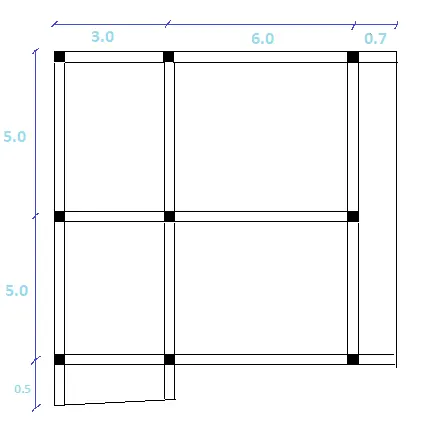
Torsional Impact of the building :
The center of mass and center of stiffness of the building is not coinciding, the building will definitely experience torsional with respect to vertical axis.
This structural plan is not effective to transfer the lateral loads due to poor connections of beams and columns offsets.
Hence, Two fundamentals modes of translation is higher than the fundamental mode of torsion.
3.
AIM :-
To make an observation of the building plan and justify the choice of the lateral load resisting system and its foundation.
Obervation:
- The given plan is asymmetric and in irregular shape.
- The columns and beams are not placed orthogonally.
- In left side there may be a missings of a column.
Lateral Load Resisting System:
- The influence of earthquake of one-direction ie. X or Y-direction earthquake will also have an effect on another direction (Y or X-direction).
- For resisting lateral forces L-shaped RC walls provided at the corners which has bi-directional strength to resist seismic forces.
- By providing this shear wall, torsional rigidity can also be maintained for the structure by distributing the mass accordingly.
- Isolated footing or box type footing is suitable for this structrual plan.