Week 1 Challenge
1)1. Uploading a .std file through web mail.
- Open software Stadd.Pro Connect edition.
- Select share option.
- Browse .std file and click add.
2. Different materials that can be designed using STAAD Pro.
Isotripic Material/Orthotropic 2D
- Concrete
- Aluminium
- Stainlessn steel
- Steel
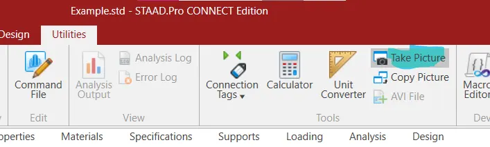
3. Yes, it is possible to capture images in STAAD Pro.
- Go to the Utilities Tab and Click on Take Picture.
4. Three methods to create a model.
- Using the Stadd.Pro Physical Modeler interface
- Using the traditional Stadd.pro analytical modeling interface
- Using the command file.
5. The steps followed to assign properties in a model.
- Open Stadd Pro
- Create a new project
- Go to the analytical Modeling
- Click on Properties
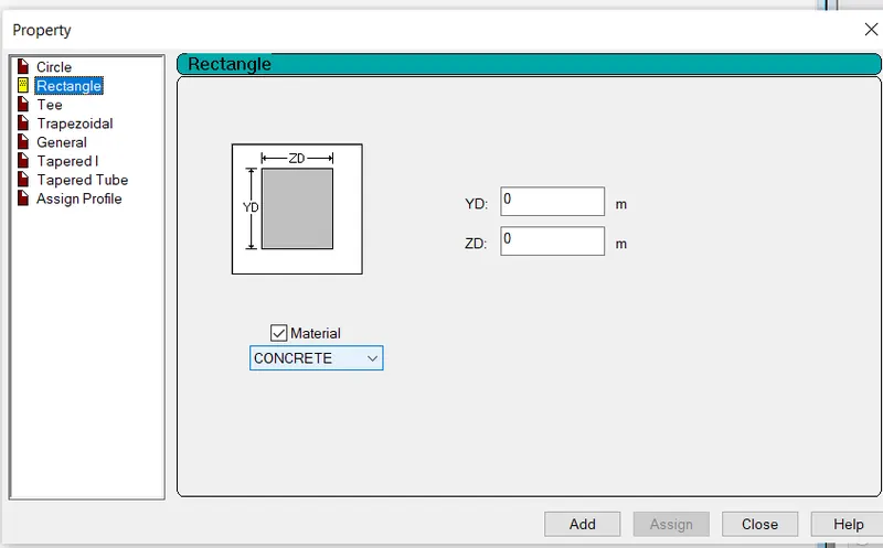
- Click on Define
- Select Property and Material.
- Give dimension
- Then add and close
- Now assign property to the view
2) 1. The six design parameter involved in RCC design are
- To create geometry
- To assign property
- To assign materials
- To assign loads
- To assign supports
- To analyse
2. There are 8 different cursor in staddpro
- Node cursor
- Beam cursor
- Plate cursor
- Solid cursor
- Plate and Solid curosr
- Geometry cursor
- Physical Member cursor
- Text Cursor
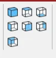
3. To generate different views for a model.
Go to the view tab.
Click on different types of views.
- Isometric View
- Top view
- Bottom view
- Left view
- Right view
- Front view
- Back view
4. A simply support where the member rests on an external structure.
It restraints vertical forces but not horezontal forces.
In stadd.pro go to the Support option and create supports.
Restaint at Fy and Mz only.
5. The topics to create DBR.
- Introduction
- Structural Layout
- Loads and combinations
- Analysis and design Methodology
- Appendix
6. Multi material design” of STAAD Pro.
- Concrete
- Steel
- Aluminium
- Timber
3) 1. Name the structure systems in STAAD Pro.
- Space
- Frame
- Plane
- Truss
2. Coordinate system adopted in STAAD Pro software.
STAAD.Pro Physical Modeler uses a conventional Cartesian coordinate system, with the global Y axis assumed as vertical (i.e., "Y up", or the height of the structure is parallel to the global Y axis).
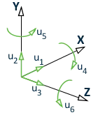
Global Coordinates System
This coordinate system is a rectangular coordinate system (X, Y, Z) which follows the orthogonal "right hand" rule. This coordinate system may be used to define the joint locations and loading directions. The translational degrees of freedom are denoted by u1, u2, & u3 and the rotational degrees of freedom are denoted by u4, u5, & u6.
- Design Based Resport. It used to create basic reoprt.
- DBR is use to specify and compile the data required for analysis and design of structural element in the project.
- Its represent the assumption and specification that are being used to develop the construction document for the project.
- It help to aviod the "Scope Creep" that can derail the project schedule and lead to budgets overruns.
4. Types of analysis options in STAAD pro.
- Perform analysis
- PDelta analysis
- Non-linear analysis
- Perform Buckling Analysis
- Perform Direct analysis
- Perform Pushover analysis
- Perform Cable analysis
- Perform Imperfection analysis
5. The difference between Fixed and Fixed But condition.
Fixed means fixed at all coordintes (X,Y,Z)
Fixed But means not all coordiates will fix. It may be free in any one or two coordinates.
Practical
1. (a)
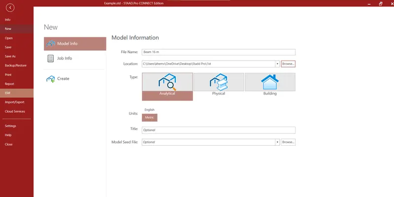
- Open Stadd.pro
- Name the file
- Choose analytical model
- Choose Metric
- Click on create
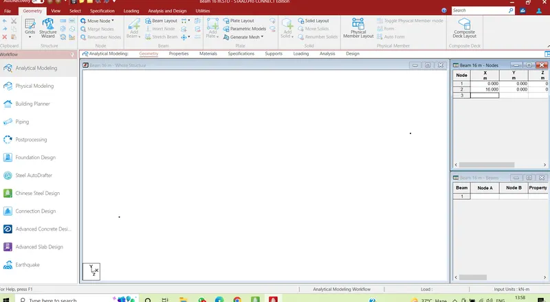
- Go to Geometry.
- Give ditance as 16m in Table
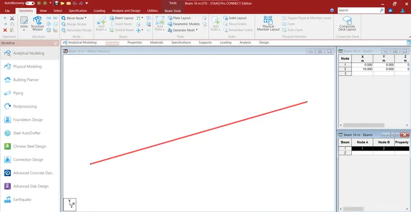
- Add beam and draw from start point to end Point.
- Assign the Property as rectangle (Concrete).
b.)
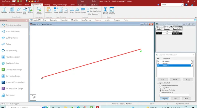
- Go to the support.
- Create support.
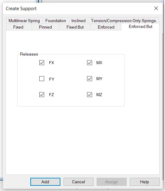
- 1st support is fixed in all ordinates.
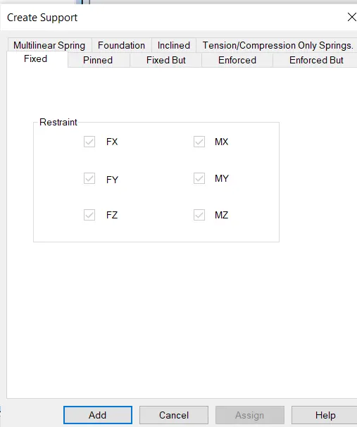
- 2nd Node is fix at only Fx.
- Create support < Go to Enfocrced But < and select only Fx.
- Now Assign the supports.
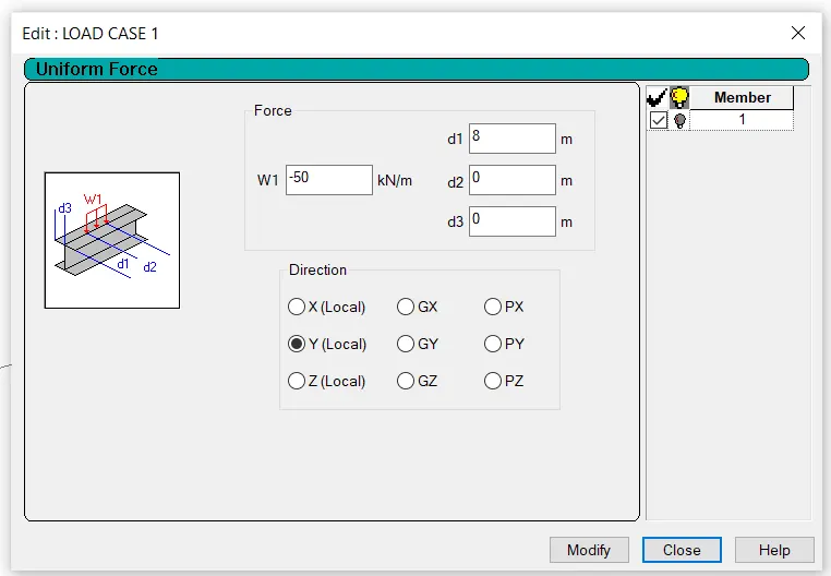
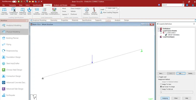
C) A point load of 50 KN at the mid of span
- Go to Load Option.
- Select Load case Details
- Add Load Case
- Click on ADD.
- Add Self Weight
- Agian Click on Add
- Click on Member Laod
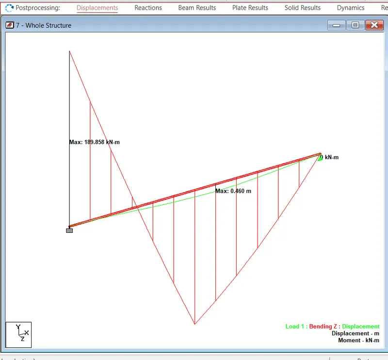
d) Draw SFD and BMD
- Now go to Analysis Tab
- Click on Analysis command
- Go to perform Analysis and ok.
- Run Analysis
- Save the file
- Showing error after analysis
- View Output to check error
- Resolve it in command file.
- Select space as plane
- Now reanalysis
- No error.
- Select the Postprocessing
- Select Displacement,shear force and bending Moment.
- Click on Annotate and tick on Shear and bending and displacement
- Click on scale and scale it as proper view.
Select Fy and Mz.
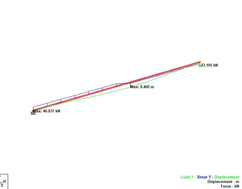
Maxm Shear Force = 46.837 KN
Maxm Bending = 189.858 Kn-m
Hence, we have given all the answers properly.