Reinforcement Detailing of Beams from ETABS output
Aim:- Reinforcement Detailing of Beams from ETABS.
Introduction:
- Beams are horizontal structural elements used for the supporting lateral loads.
- RC beams bear loads from floors and Wall loads,Finishes etc.
- The design and detailing of RC beams involves the Section of beam and the quantity of longitudinal and shear reinforcement that will satisfy ultimate and serviceability limit state requirements.
- Afterwards, It is very important that the beam reinforcements are placed and arranged properly on site, to avoid construction error.
Procedure:
- Open the Downloaded file in Etab.
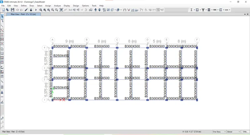
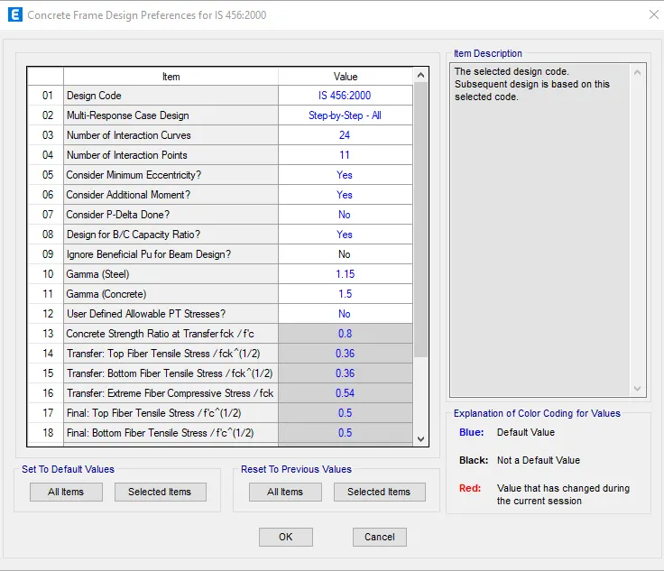
- Go to design tab and click on concrete frame and select view preference.
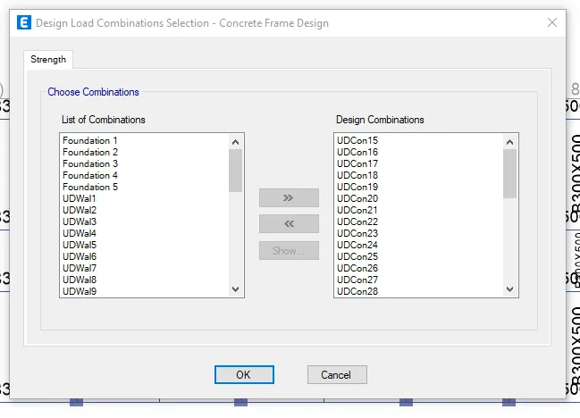
- Next we have to check the load combinations.
Concrete Frame Design :
- Go to the 'Start Design/Check option and click on it.
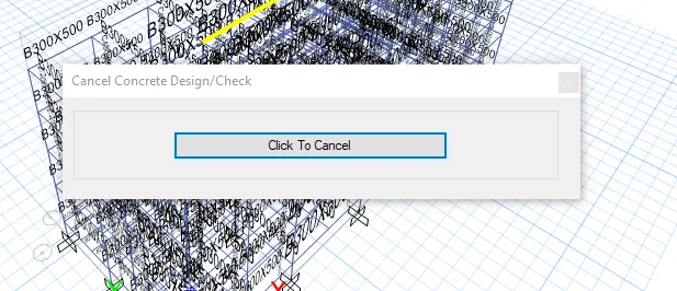
- Verify all the Member passed.
- After finishes Designing
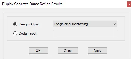
- Go to conrete frame and click on design info and set longitudinal reinforcing as shown below.
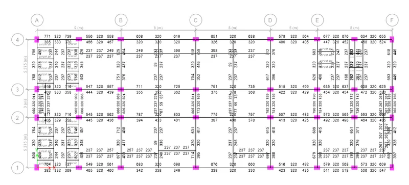
Reinforcement Detaling are shown in above pic.
Provide details of longitudinal and shear reinforcement for the two continuous beams
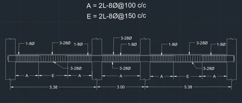
- 3 span continuous beam along grid A.
- Provide 3-28 dia at the top and bottom, as shown.
- Provide 1-8 dia at the top supports for the continuous beam, as shown.
- The maximum Ast for the bottom support is 1766mm and bottom middle is 702 mm^2
- The maximum Ast for the top support is 1889mm and top middle is 453 mm^2
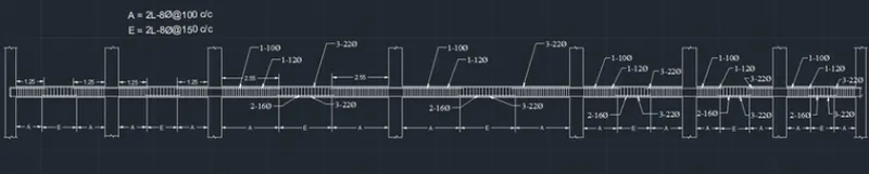
- 7 span continuous beam along grid 3.
- Provide 3-22 dia at the top and bottom, as shown in the below.
- Provide 1-10 dia and 1-12 dia at the top supports and we provide 2-16 at the bottom middle for the continuous beam.
- The maximum Ast for the bottom support is 1061mm and bottom middle is 1493 mm
- The maximum Ast for the top support is 1915mm and top middle is 479 mm^2
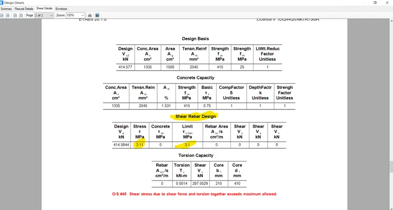
It is noted that central span of Grid-A RC beam is nearly failing due to higher shear stress. As per the above shear force value (3.11 MPa) against the maximum allowable shear stress (3.1 MPa), is failing but passes numerically. This design shear force is arrived in philosophy of Capacity design concept. This can be resolved in any of the following process.
a) Optimizing provided flexural reinforcement.
b) Reducing depth of RC beam which in turn reduce stiffness and flexure requirement.
c) Increasing concrete grade will increase allowable shear stress limit.
Calculate value of the maximum shear force in any one of the spans in both the continuous beams, as per clause 6.3.3 (b) in IS 13920 - 2016.
- Select the beam and rgiht click, a new tab appears.
- Select an combination and click on details, select shear details.
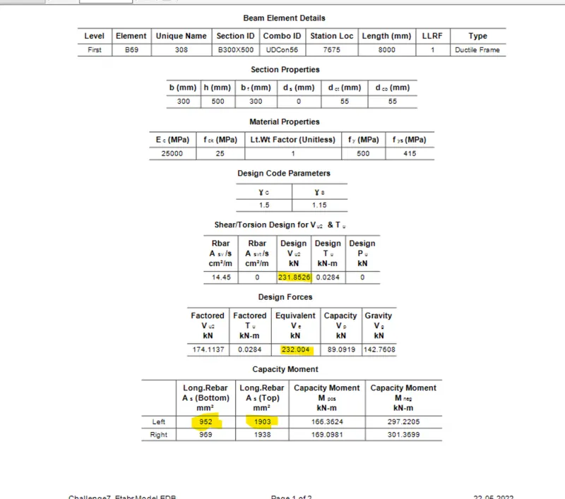
- UDcons69,
- Ast at top = 1903 mm^2
- Ast at bottom = 952 mm^2
- Design shear force Ve=232.004 KN
- Factored shear force = 174.1137 KN
- Design shear force >Factored shear force,Hence analysis is correct.
Calculating value of the maximum shear force in any one of the spans in both the continuous beams, as per clause 6.3.3 (b) in IS 13920 – 2016.
1) For Sway to Right :
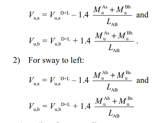
Vu,a = 231.56
Vu,b= 175.6
RESULT:
- The beams are designed in detail (as given data) from the Etabs software.
- The details of longitudinal and shear reinforcement for the two continuous beams is provided.
- The value of maximum shear force in the continuous beams using the Etabs software is also calculated.