Analysis & Design of RCC shear walls in the model using ETABS
AIM : Analysis & Design of RCC shear walls in the model using ETABS
Introduction :
- Shear wall is rigid vertical diaphragms capable of transferring lateral forces from the outer walls, floors, and ceilings to the ground level in the parallel direction of their planes i.e. reinforced-concrete walls or vertical trusses.
- This wall resists the lateral loads that are imposed on the structure due to wind, earthquake, or sometimes due to hydrostatic or lateral earth pressure.
- Shear wall buildings are a common choice in earthquake-prone countries.
- It reduces earthquake damage in structural and non-structural elements such as glass windows and construction materials.
- Buildings with shear walls have shown very good performance during earthquakes in high seismic areas.
Prodedure :
STEP 1
- To open the downloaded file in Etabs.'
- Before analysis check any errors.
- Analyse the model.
- After analysing go to the Shear Wall Design.
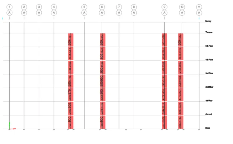
Now Design of shear wall is completed.
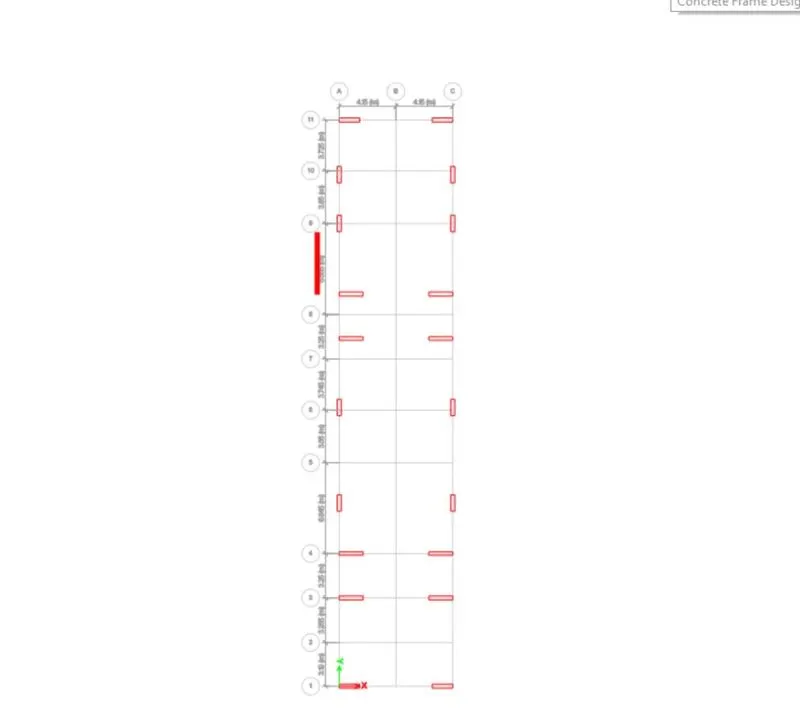
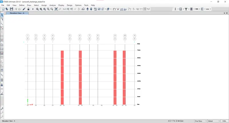
Go to the Elevattion and select elvation 11.
Now go to the Shear wall Design and click on Design info.
A new window will open then select one by one longitudianl bar , shear reinforcement and Boundary wall.
Pier Longitudinal reinforcement Detailing.
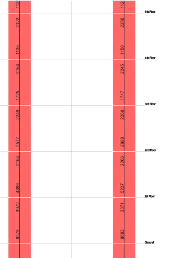
Pier Shear reinforcement detailing
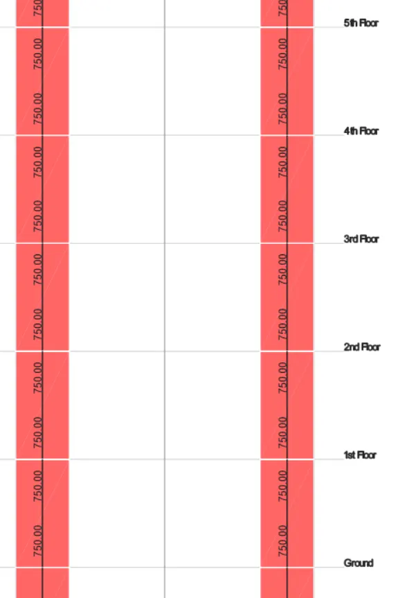
Boundary Zones
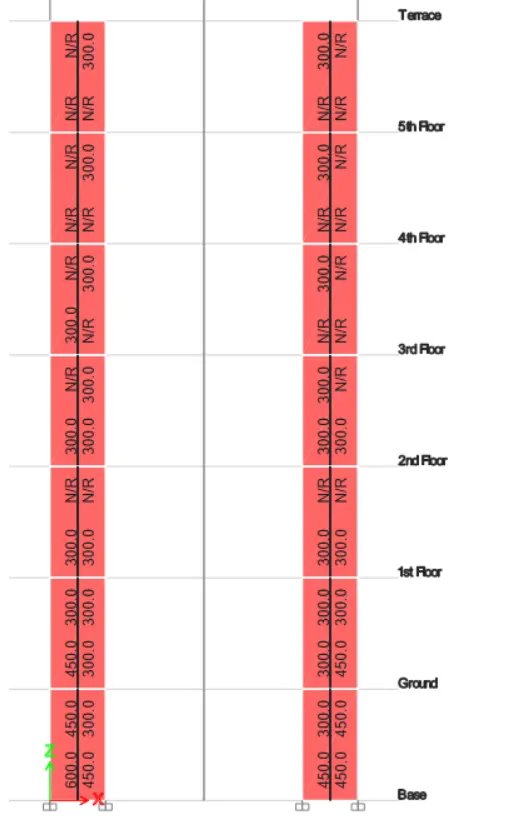
Longitudinal steel ratio, boundary element length and shear reinforcing ratio from the design results.
The total height of wall 'hw' = 21000mm
Length of the wall 'lw' = 1500mm
Checking the types of wall ( IS 13920-2016 Part 10.1.4)
`frac{h}{l} = frac{21000}{1500}`= 14
The ratio is greater than 2 hence it is selender wall.
* The largest diameter of reinforcement shouldnot exceed 1/10th of thickness of wall.
`frac{300}{10} = 30`
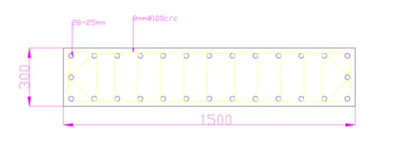
Hence we used 25 mm dia for rebar detailing.
* The maximum spacing of `frac{Longitudnal}{transverse}` rebar shouldnot exceed.
i) 1/5th of horizontal length (l) = 1500/5 = 300mm
ii) 3 times of thickness (t) = 3x300 = 900 mm
iii) 450mm
Hence, we take maximum 300 mm spacing for vertical and horizintal rebar for RC wall.
* Minimum horizontal reinforcement (IS 13920-2016, Table 1)
(Ph)min = `0.0025+0.5(frac{hw}{lw} -2)(Ph-0.0025)` | (Ph = 750/300x1000) = 0.0025 |
= 0.0025 +0.5(`frac{2}{3}`-2)(0.0025-0.0025)
0.0025 + 0 = 0.0025
Minimum Area of horizontal Reinforcement = 750 mm^2/m
Taking 8 mm dia at 100 mm spacing = 2x`frac{π}{4}`x 8^2/0.100
= 1005 mm^2
* Minimum boundary reinforcement in Left side( IS 13920-2016 Table 1 C-10.1.6)
(Pv, be)min = 0.008
=0.008 x 300 x 650
= 1440 mm^2
Minimum Area of boundary Reinforcement In left side = 1440 mm^2/m
* Minimum boundary reinforcement in Right side( IS 13920-2016 Table 1 C-10.1.6)
(Pv, be)min = 0.008
=0.008 x 300 x 450
= 1080 mm^2/m
* Mimimum net vertical reinforcemnet ( IS 13920-2016, Table-1, C-10.1.6)
(Pv, net)min = 0.0025 + 0.01375 (`frac{tw}{lw}`)
= 0.0025 + 0.01375 (300/1500)
= 0.00525 x 1500x300
= 2363 mm^2/m
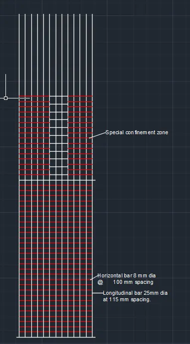
*Boundary element special confining reinforcement (IS 13920-2016, C-10.4.4)
Ash = 0.05sv h (`(frac{fck}{fy})`
Sv = 100 mm
Providing 8 mm dia bars. hence Ash = 50.24 mm^2/m
h = 201 mm
Providing 8mm dia bar @ 100mm c/c
Ash = 1005 mm^2
Total Vertical bar = 13128/490 = 27 bars
*But we taking 28 bars for uniformity of bar.