Creating 3D Isometric view of various structural elements in AutoCAD
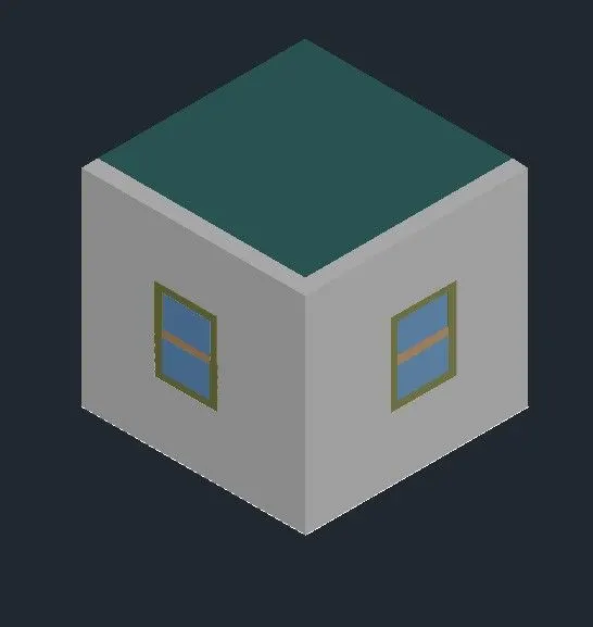
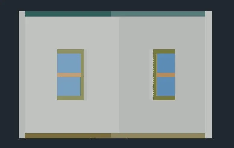
Aim: To create a 3D Isometric View of the building with plan and elevation given.
Procedure:
- Open AutoCad,
- Select Imperial system
- Set Units , select Engineering with precision 0'0.0"
- Set the Limits; Lower limit as 0'0.0",0'0.0" and Upper limit as 1000'0.0",1000'0.0"
- In the command prompt, command ZOOM and select All
- Now change the Working space from Drafting and annotation to 3D modelling
- The plan is cretaed in the top view with all the given datas in the question
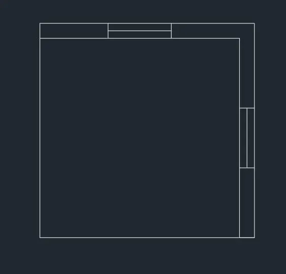
- Now select the South West isometric view
- Arrange the ucs such that we can edit the required wall or portion.
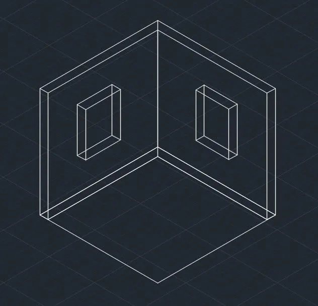
- Draw the rectangle for window, and extrude it
- Using the SUBTRACT command, subtract the windows from the main wall
- Now for frame work, draw the rectangles of given dimensions and extrude it again
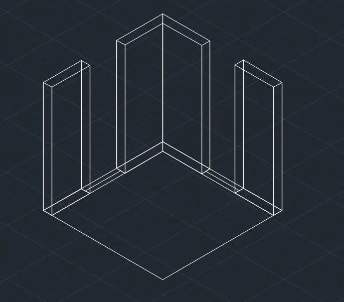
- Select the realistic view
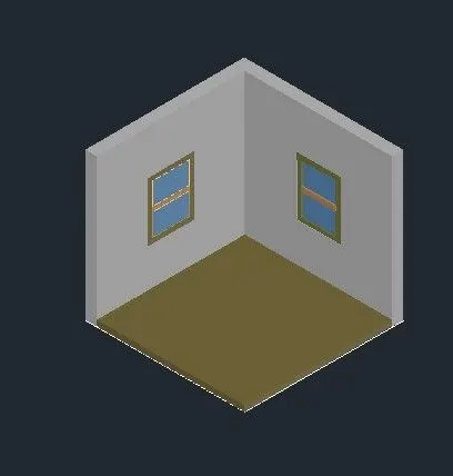
- Now From the visualisation, select material browser, select the material, and pick up it to the needed area
RESULT:
2.
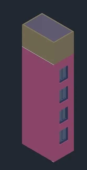
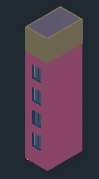
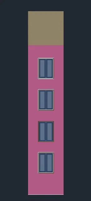
Aim: To create the 3D view of building facade as given in the plan and elevation, considering the detailing of window
Procedure:
- Open AutoCad,
- Select Imperial system
- Set Units , select Engineering with precision 0'0.0"
- Set the Limits; Lower limit as 0'0.0",0'0.0" and Upper limit as 1000'0.0",1000'0.0"
- In the command prompt, command ZOOM and select All
- Now change the Working space from Drafting and annotation to 3D modelling
- The plan is drawn with the datas given in the question in Top view
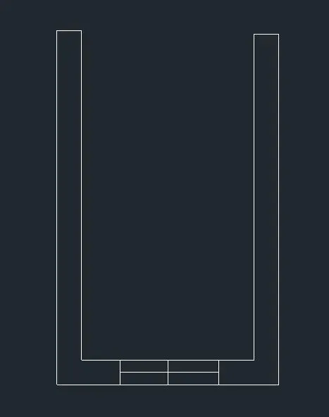
- Hatch the wall using hatch command
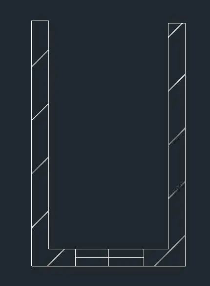
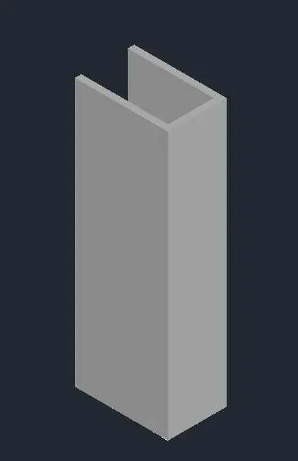
- Select the South west isometric view and extrude the building to the required height
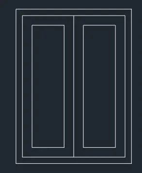
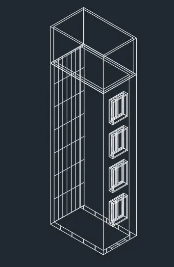
- Adjust the ucs and draw the detailed window using the rectangle command, line command, offset command and trim command.
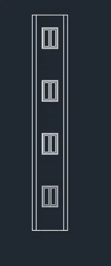
- Take the front view and place the windows at requied height
- Now extrude the window frame
- Using the subtract command, subtract the window from the building
- Now again make a rectangle and extrude it, to make the glass of the window.
- Draw the back side of the building and extrude it to the building height
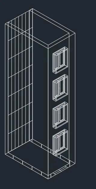
- Now adjust the usc in the south isometric view and draw the parapet with the given height
- Select the Realistic view
- Using Visualization, select material browser, select the required material at the appropreate side.
RESULT:
3.
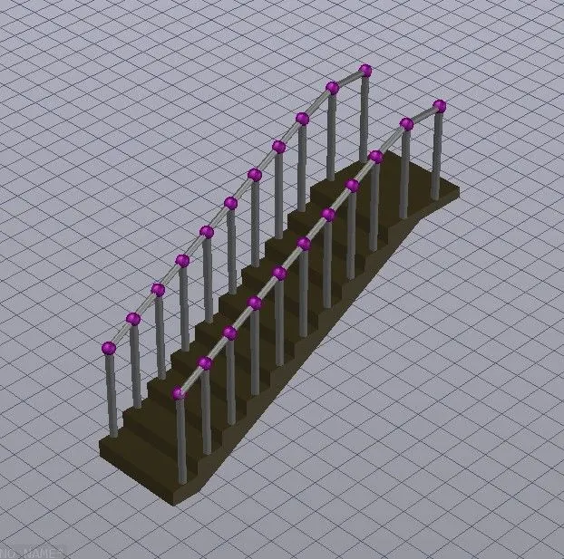
Aim: To create the isometric 3D view of the stairs with rails
Procedure:
- Open AutoCad,
- Select Imperial system
- Set Units , select Engineering with precision 0'0.0"
- Set the Limits; Lower limit as 0'0.0",0'0.0" and Upper limit as 1000'0.0",1000'0.0"
- In the command prompt, command ZOOM and select All
- Now change the Working space from Drafting and annotation to 3D modelling
- Draw the plan of the stairs in the top view and dimension it
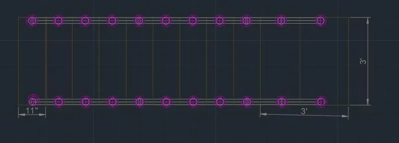
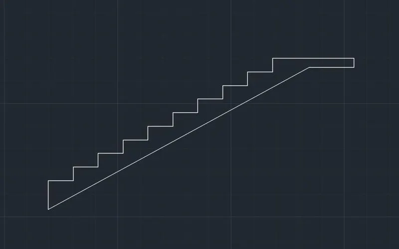
- Now select the front view and draw the stair with rise 6" and tread 1'.
- Now using the South west isometric view, extrude the stair to required width
- Using circle command, draw circle of 2" dia and the extrude it to get the cylindrical shape
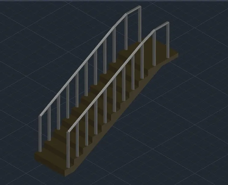
- Using the line command, rails are drawns and is extruded to 2" to get a thickness.
- Now take the Realistic view
- Using Visualization, select material browser, select the required material at the appropreate side.
RESULT
4.
Aim: To create 3D view of wall with spread footing
Procedure:
- Open Auto Cad,
- Select, Decimals with precision 0.0 and select units as millimeter
- Now set the Limits: Lower limits as 0.0,0.0. and upper limit as 1000.0,1000.0
- In the command prompt, command zoom all
- Now change the Working space from Drafting and annotation to 3D modelling
- The plan of the wall with the spread footing is drawn using the datas given in the question in top view
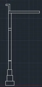
- Now take the front view, and draw the section of wall footing.
- Hatch the areas required with appropreate hatches
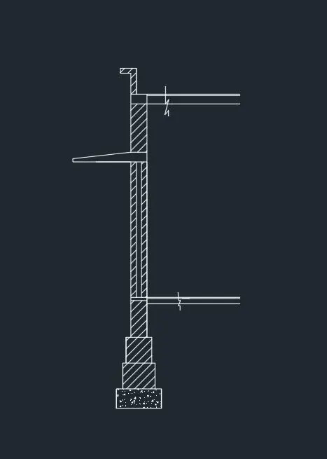
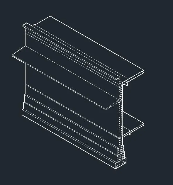
- Take the south west isometric view
- Now extrude the full drawing, with required height
- Using Visualization, select material browser, select the required material at the appropreate side.
RESULT:
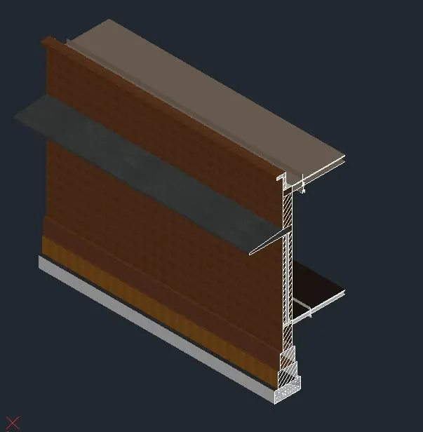
Hence we have created Creating 3D Isometric view of various structural elements in AutoCAD.