Creating Architectural and Structural model with 3D rendering using REVIT
AIM : Creating Architectural and Structural model with 3D rendering using REVIT
1)
Selecting MUTLI-UNIT RESDIENTIAL APARTMENT
2) Assuming reasonable assumptions for geographic and location details for our project modeling. Based on assumptions and type of structure selected identifying the modeling requirements from NBC.
- Acoording to NBC it comes under GROUP A-resdiential building,sub-divsion A-5.
- The apartment is suited on plain terrain and at mid of the city (Patna)
- The width of road passing the apratment is 50'
- The overall height of the apartment is 45'.
- According to NBC,height of the building should not exceed 1.5 times the width of the road,45'<52.5',hence ok.
- The haibtal height of the room is 10'.
- Thickness of the wall will be considered as 8", and 5" hence ok per as table 2.
3) Using the structural model, include the following components based on the type of structure selected
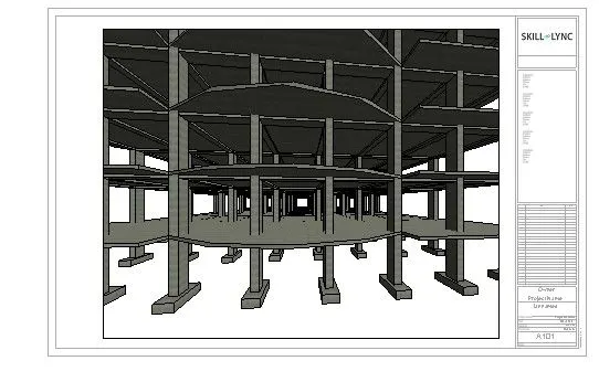
a. Foundation – Isolated / Wall/Matt Foundation
b. Columns
c. Beams Connected to Columns
d. Roof Framing/ Truss
e. Floor / Decks
f. Floor Openings for Elevators and Stairs
PROCEDURE:
- Create a architectural template file ans save as acrh-1.
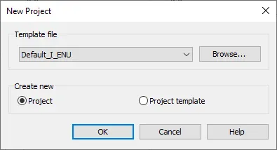
- Create the structural template file and save as struct-1.
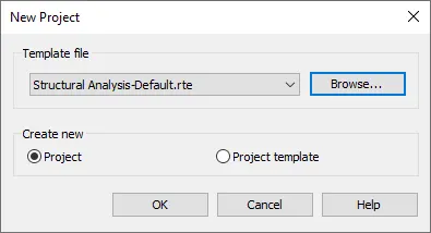
- Simialry create the another architectural template file and save as mutli-1.
- Open the arch-1 file and grid a vertical grid named 1 and horizontal grid name A.
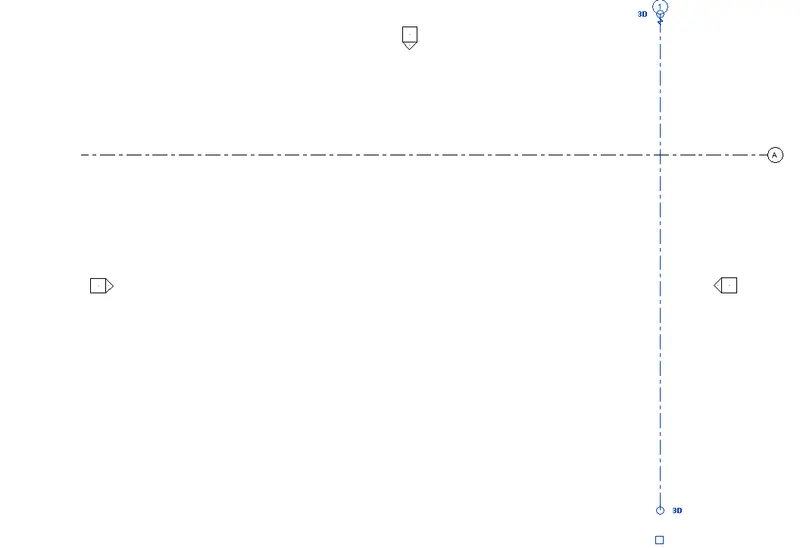
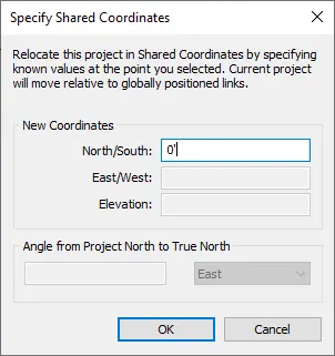
- Now got to view toolbar and select specify the shared coordinate from project loaction.
- Specify the coordinates as 0',0'.
Step 1 :
- Once done create the as central file by clicking collaborate option.
- Simlalry repeate the same for structural file also from grids to central file option.
- Now open the mutli file and select the manage link.
- Link above arch-1 and struct-1 file .
- Set the coordinates using acquire coordinates nad relocate coordinates.
- Once done,save this as central file and exit.
- Open the struct-1 file and draw horizontal and vertical grids.
- Set as elevation view and add levels to it.
Step 2 :
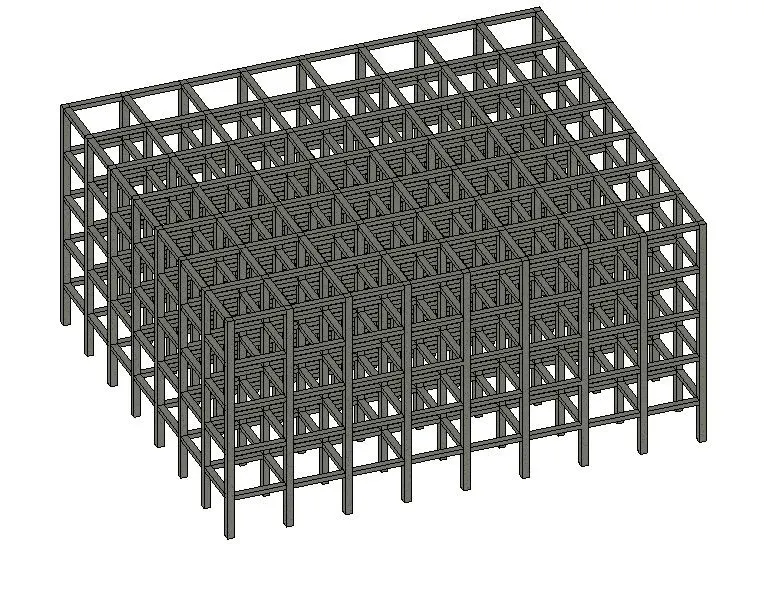
- Now select rectangular column (18x 24") and add to ground floor upto top level
- Select the beam (12"x 18") and place between column.
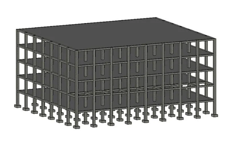
- Select isolated footing (3'x4')and add to the foundation level.
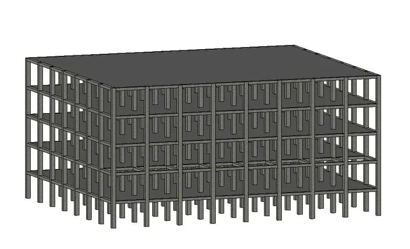
- Select floor deck (6") and use boundry pick lines add to the ground floor.
- One done,select all the components except footing.
- Copy to clipboard and select apply to selected levels in paste option.
- Once done,synchronize the changes to the central file.
RESULTS :
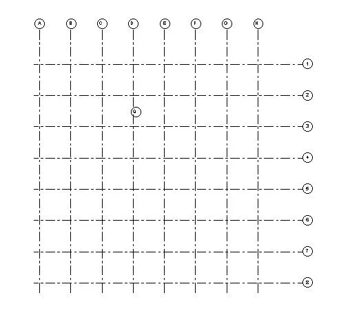
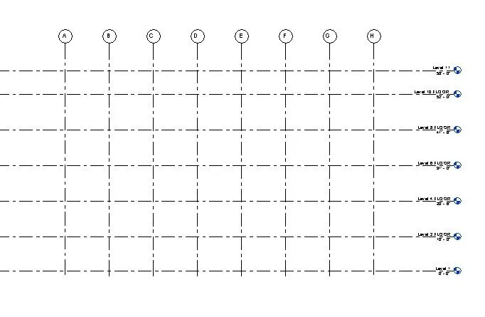
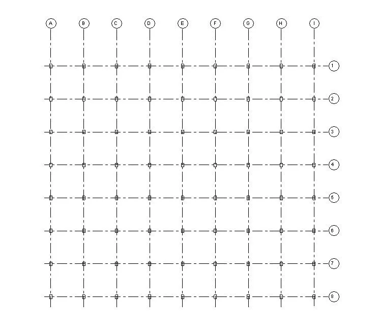
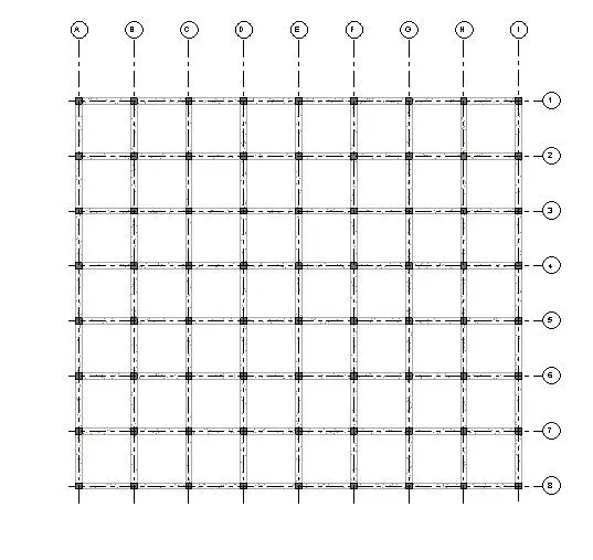
4)
AIM: To create structural model and adding below given components.
a. Wall Layout with appropriate material and finishing
b. Exterior façade with fancy finish
c. Interior partition walls to size rooms
d. Components to add details to a room ( Desk, Chair, Lighting, Plumbing fixtures)
e. Add components such as stairs Elevators
f. Have at-least one side of the building with curtain walls and glass panels
g. Include interior and exterior lighting fixtures
h. Place proper topographic components from outside ( Trees, Parking, Plants) to add details to the model
PROCEDURE:
- Before starting with columns in structural model,link the file to arch-1.
- Set the coordinates and select copy option from collborate toolbar with select link.
- Select the grids and levels using copy option.
- Once done go to visibilty graphics option and set revit link as custom.
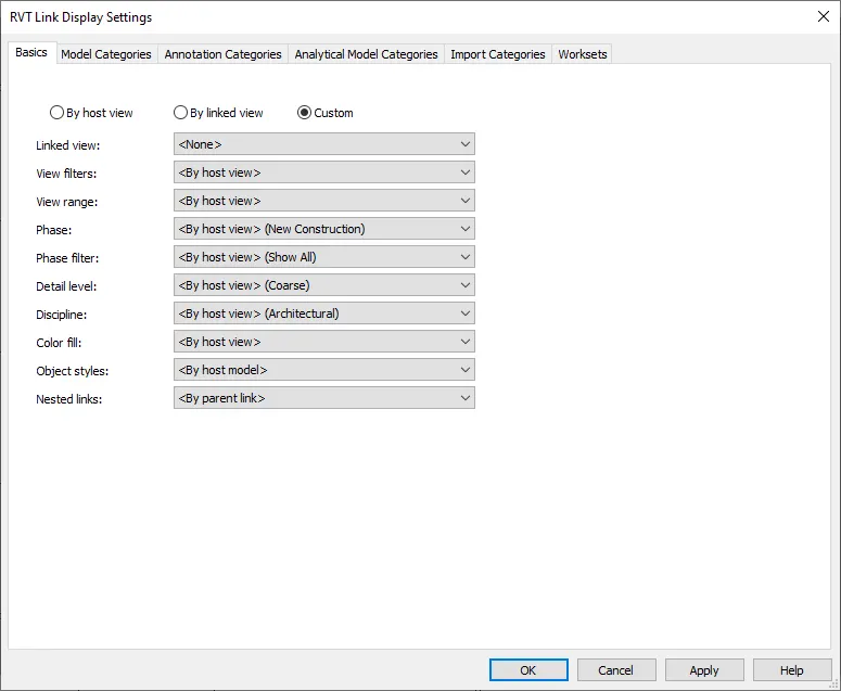
- Off the grids and levels of the revit link.
- Now add the wall, floor plan including bedroom,kitchen,bathroom,hall,dinning and balcony.
Creating outer wall : Architectural < Wall tab < Select 8" wall.
Creating inner wall : Architectural < Wall tab < Select 5" wall.
Creating Curtain walls : Architectural < Wall < Select wall type like curtain.
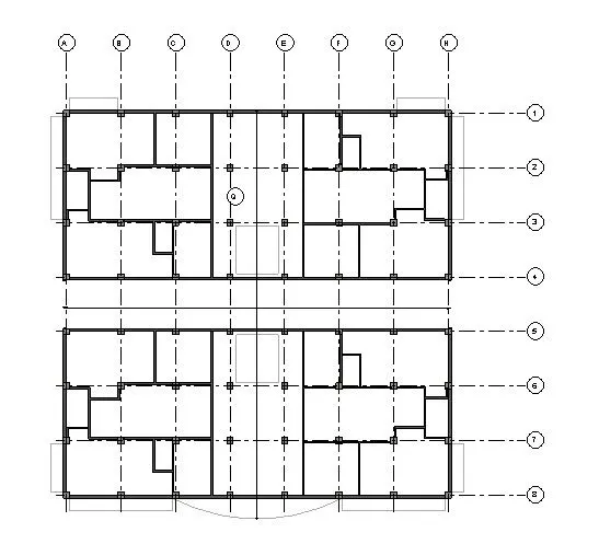
Adding Doors : Architectural < Door < Adding from given family or Load family Accoding to desire.
Adding windows : Architectural < Windows < Adding from given family or Load family Accoding to desire.
Creating srairs : Architectural < Stair < Create stairs
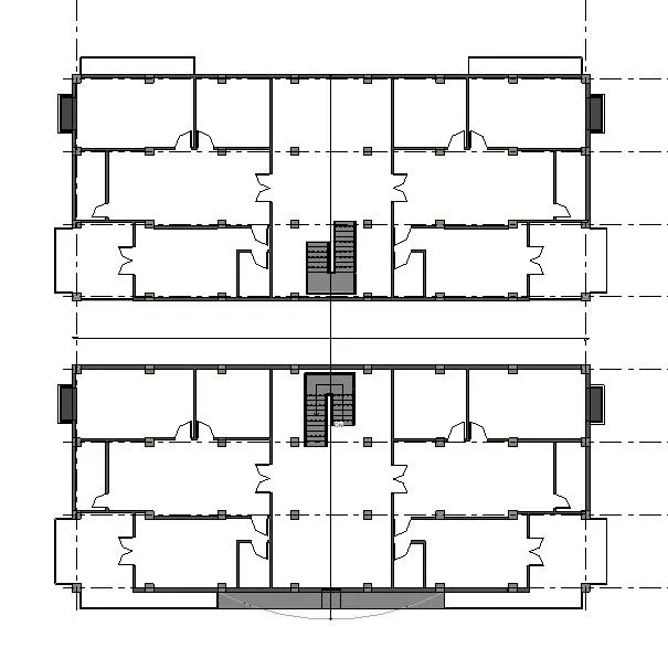
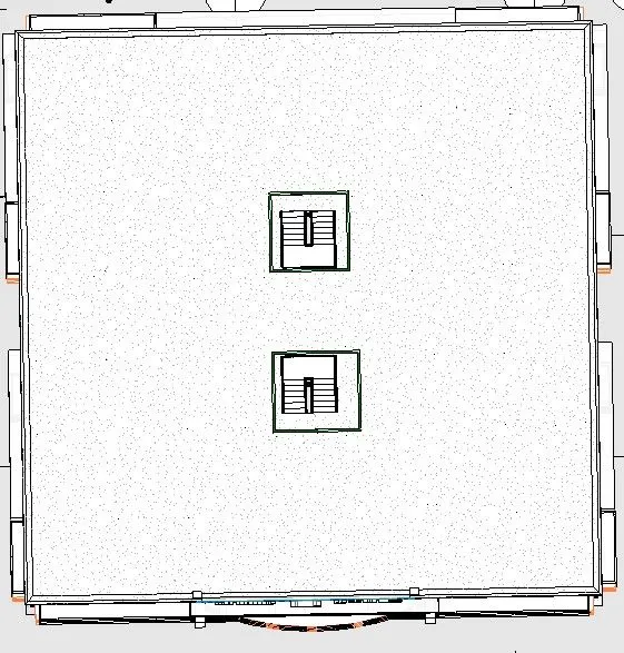
Providing Shaft for Stairs : Architectural < Shaft
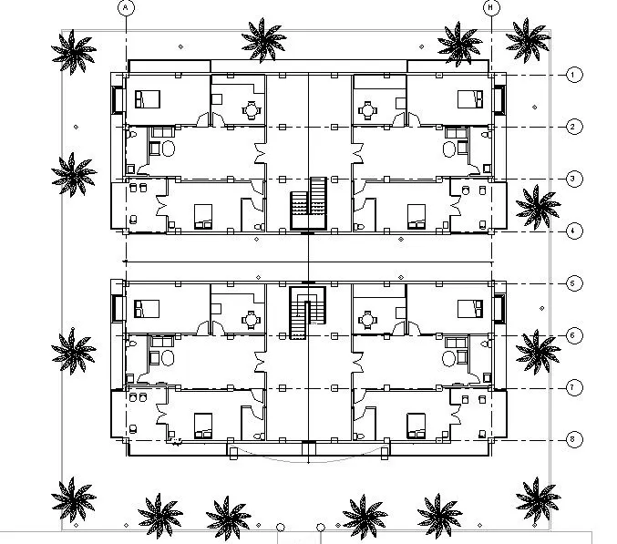
- Adding components like Table, Sofa, Bed, Sink,Plant, Light etc.
- Adding toposurface : Architectural < Massing and site < Toposurface (Create desire toposurface)
5)
AIM: To create sheet template for different views.
PROCEDURE:
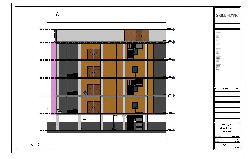
- Before creating the template,go to view toolbar and create floor plan,structural plan,elevation and sectional views.
- Once create,select the sheets option and click one.
- Edit the sheets using edit family option.
- Once adding the details,click on view and select the view to be placed in the sheets.
- Set the view using scale.
- Repeat the same for remaining view.
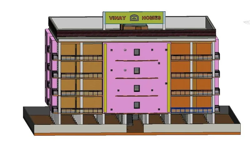
RESULT:
Floor plan
Elevation
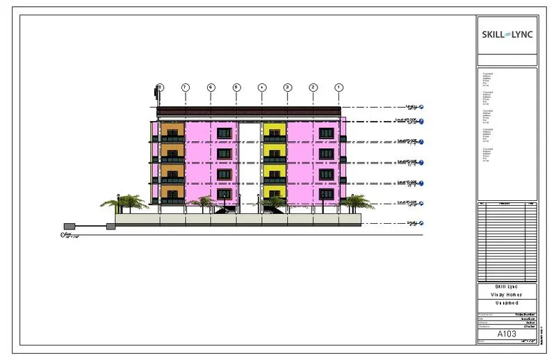
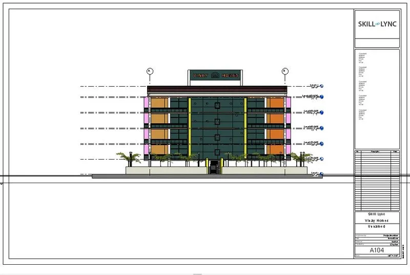
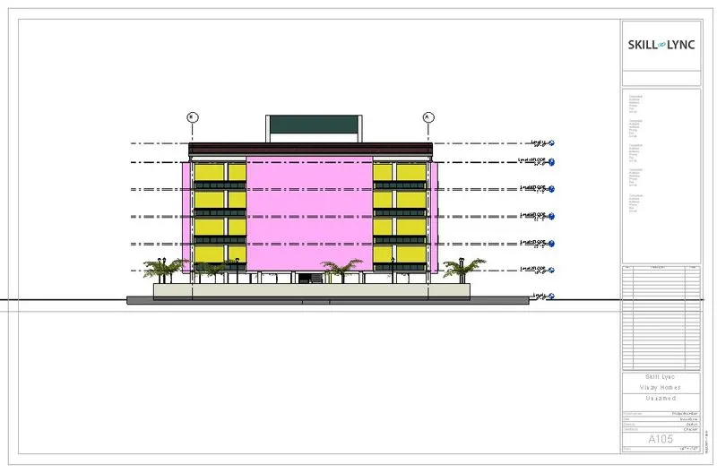
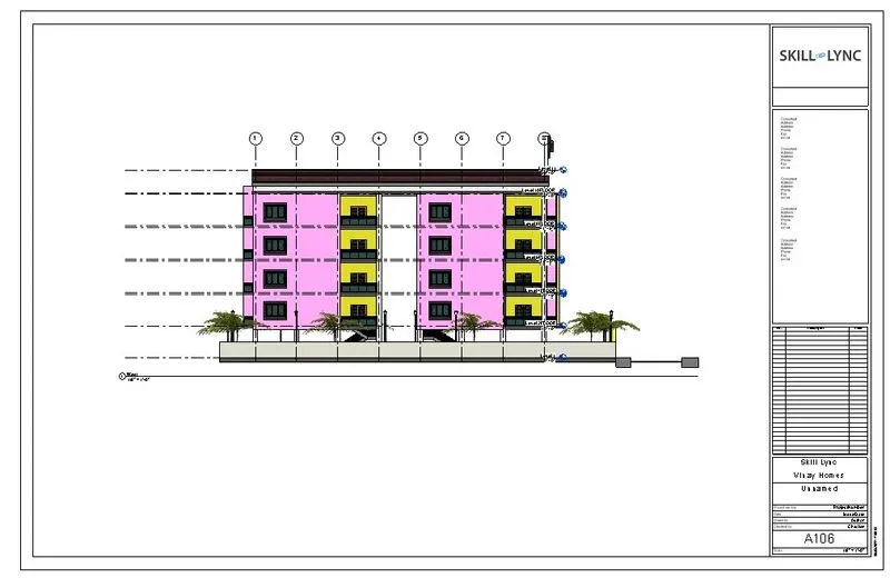
Section
6)
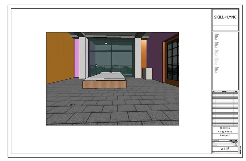
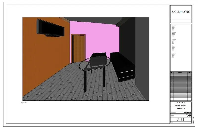
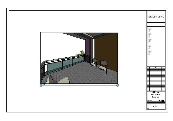
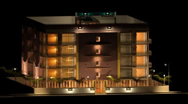
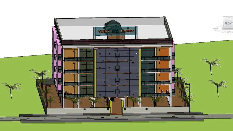
AIM: To create render image and add to sheet templates
PROCEDURE:
- Select the camera from 3d view in view toolbar.
- Set the view with proper angle.
- The view will be saved automatically.
- Select the view,click on render option in 3d view.
- Set the render setting and render.
7)
AIM: To print the sheest of strcuturala nd architectural sheets .
PROCEDURE:
In order to print,
- Edit the sheet template.
- Add the floor views,structural view,section to sheets.
- view the saved sheets and enter crtl+p/print option in file menu.
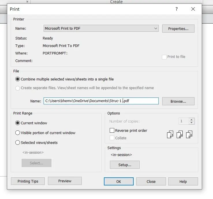
- Set the print option,enter.
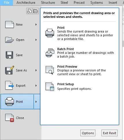
Hence We have Created Architectural and Structural model with 3D rendering using REVIT.