Project 2_Design & Analysis of a Hostel building at Guwahati, Assam
Aim:
To model and to analyse G+3 building with relevant seismic inputs based on the given data, using ETABS software. Also for the resultant column reactions, Deep foundations have to be designed with Piles and pilecap using SAFE software. Also Typical floor structural plan, Column rebar, Beam rebar, Pilecap rebar and Tie beam rebar need to be detailed using AutoCAD.
Introduction :
The Project informattion are -
- Location – Guwahati, Assam
- Function – Hostel block in an academic institute
- Soil Type - 3
- Walls - ACC Blocks
- Piles for Foundation - 10 meter
- Piles dia - 500 mm
- M25 grade of concrete with Fe500 for longitudinal reinforcement and Fe 415 for shear reinforcement is to be used.
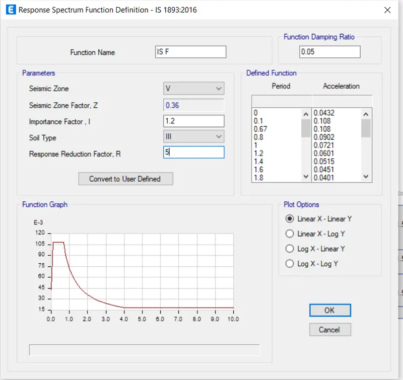
Note : Guwahati Assam is in Seismic Zone - V
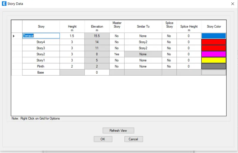
Guwahati, Assam is also Floody area So we take 2 m Plinth Level.
-
The following design IS codes will be required for reference:
- IS 875 part 1
- IS 875 part 2
- IS 13920
- IS 1893
- IS 2911 part 2
- IS 456
- SP 34
Procedure :
- Open Etabs
- Open New Model
- Select IS Code - IS 456-2000 and IS Code - (800-200)
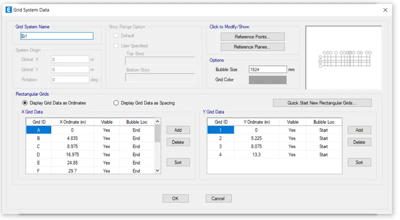
- Now Go to Grid System and input desired data.
- Story level assignment
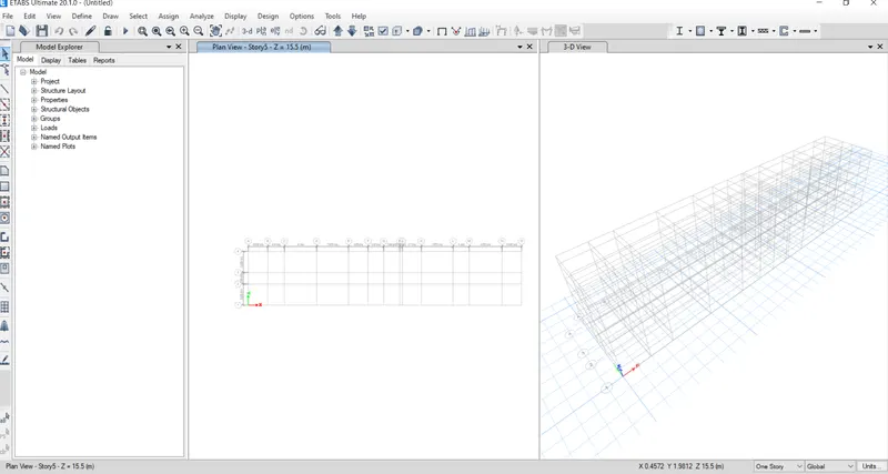
- Verify the Model
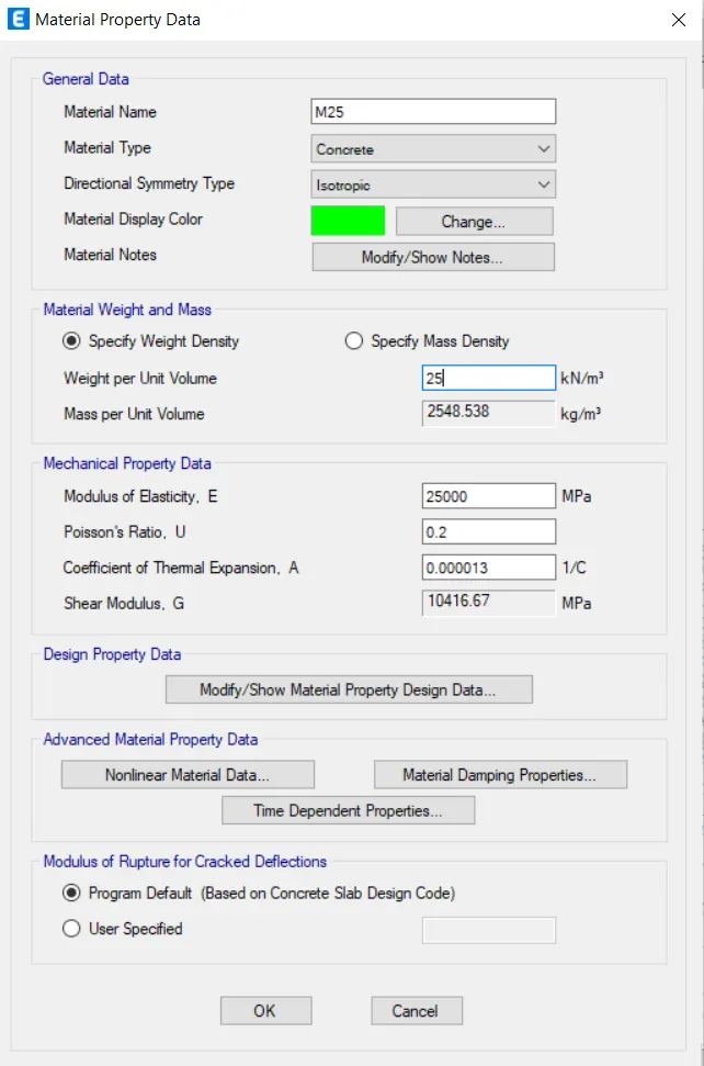
Defining Materials :
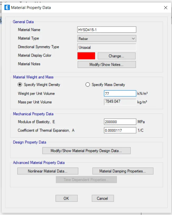
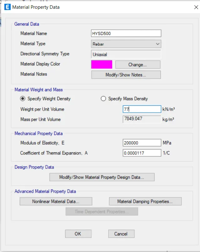
- Go to Define Tab and select material property.
- Select new property as concerete M25.
- Agian Click new property and select Rebar Hysd 415 and Hysd 500.
Section Property
Frame Section
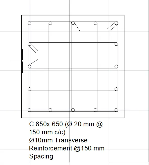
- Define C650 x 650
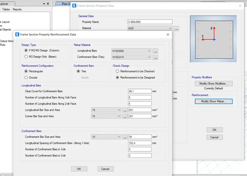
- Define C450 x 650
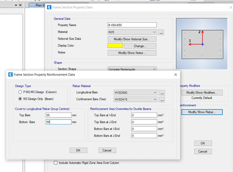
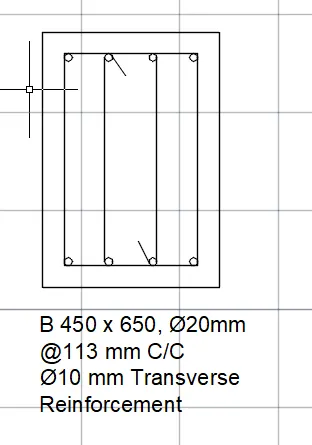
- Define B450 x 650
Section Property
Slab section
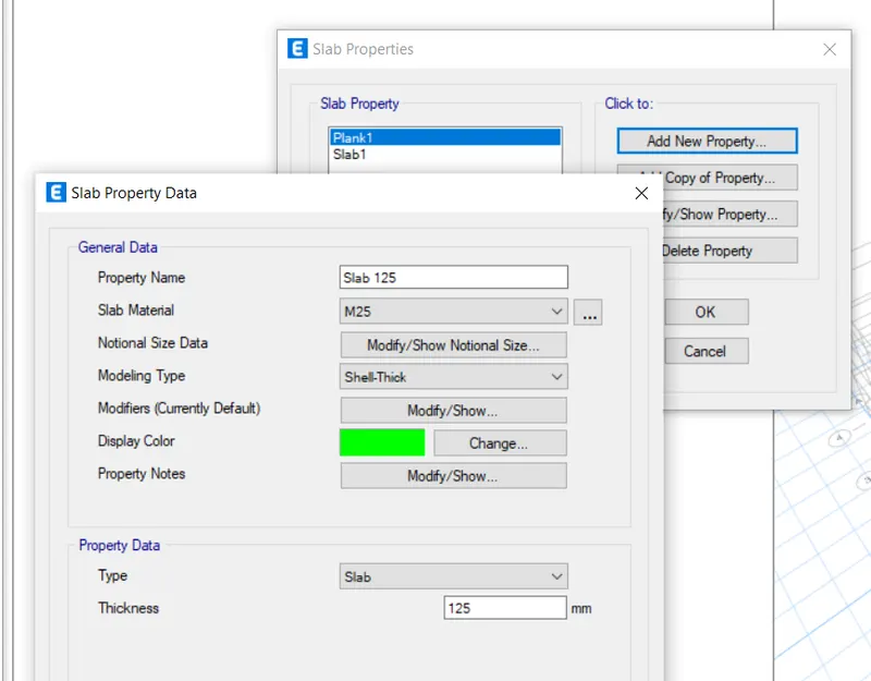
- Define Slab125 (Floor)
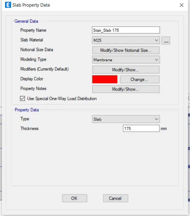
- Define Slab 175 (Stair)
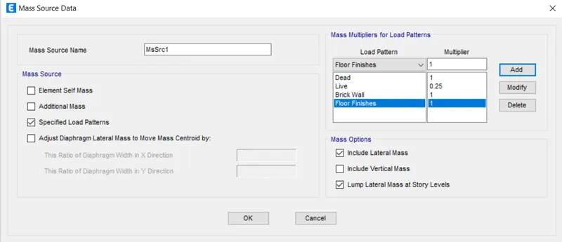
Define Mass Source
Define Response Spectrum Function
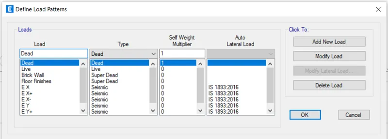
Define Load Pattern.
Time period is calculated as per clause number 7.6.2 of IS 1893
T=0.09h/sqrtd
Tx=(0.09*16.85)/(67.7)^0.5=0.184 Seconds.
Or Ty=0.09*16.85/(13.3)^0.5=0.415 sec
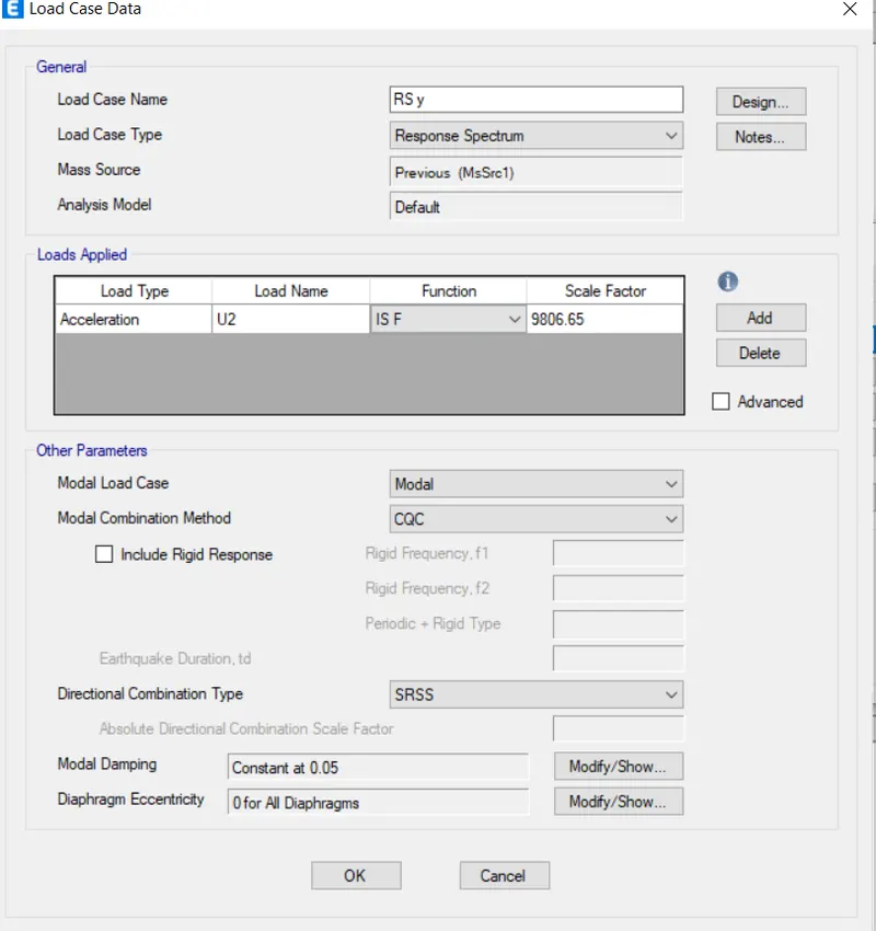
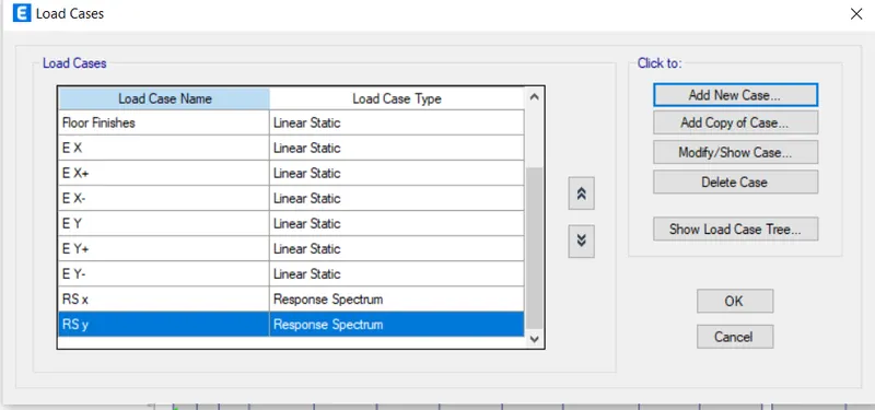
Define Load Case
Go to Define < Load Case < Add new case. (RS x and RS y)
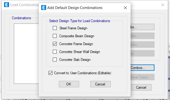
Define Load Combination
- Go to Define Tab
- Select Load Combination
- Select Default and tick on Concrete frame design.
Draw Beams, Columns and Floors.
- Go to Quick Draw Column Tools and Draw the columns on all story.
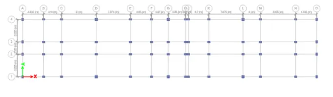
- Go to Quick Draw Column Tools and Draw the Beams on all story.
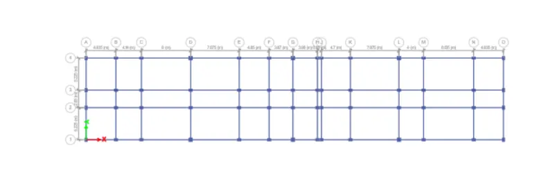
- Now Draw the Secondary Beams on Desired Story.
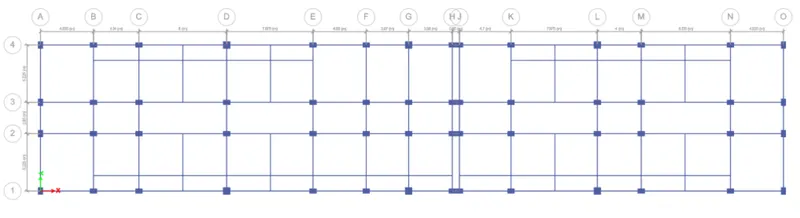
- Draw the Slab on Desired Story.
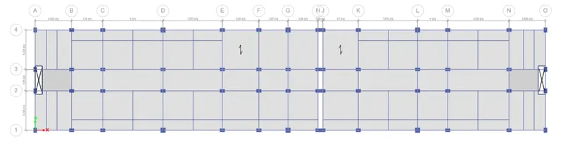
Assigning Loads
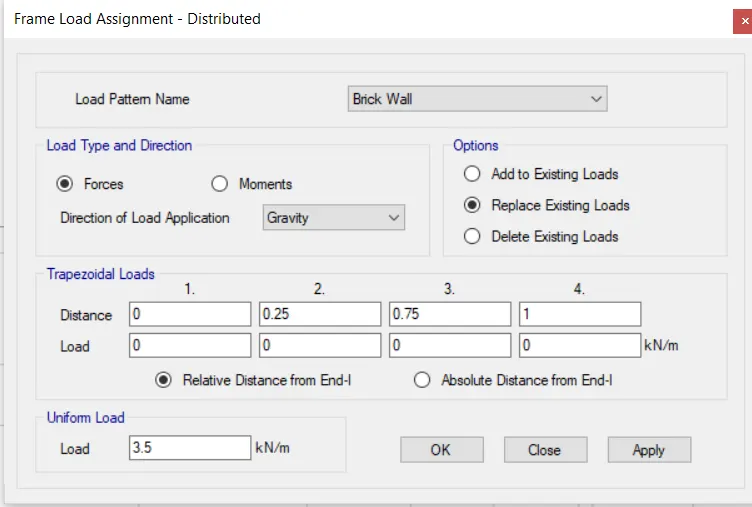
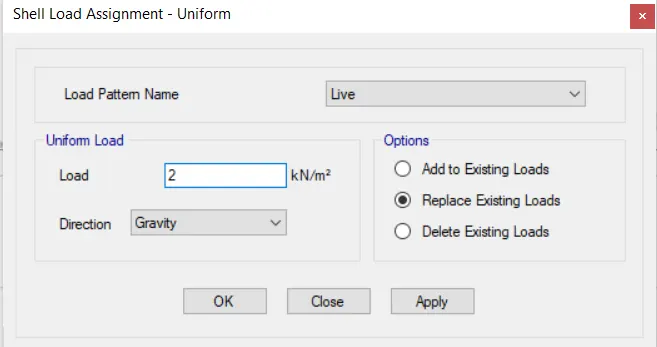
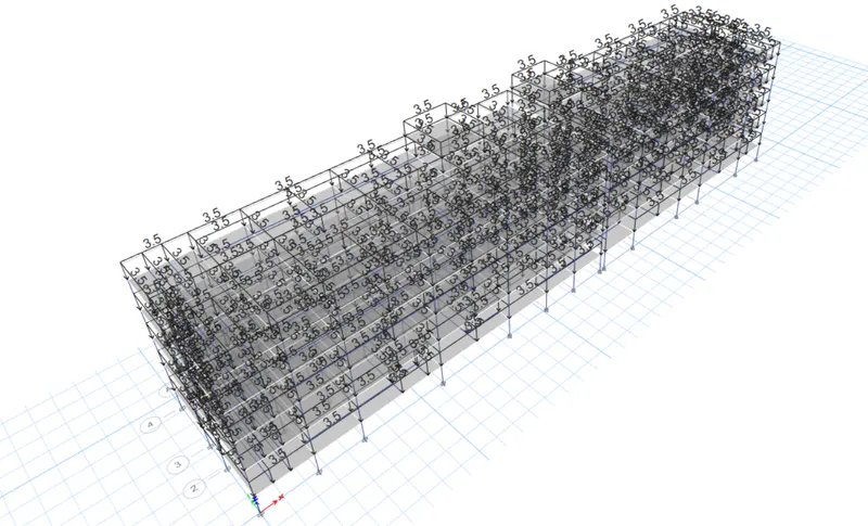
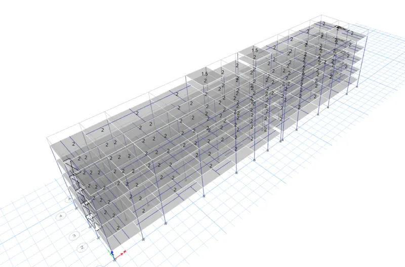
- Go to the Assign Tab and select Frame load and Shell load and Apply one by one by selecting Members.
- For Floor Give 2 KN/m^2 and For Beam give 3.5 KN/m^2.
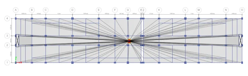
Assigning Diaphragms
- Select all the floors
- Go to Assign tab and select shell and then Diaphragm.
Assign Joints
Go to Assign Tab and select fixed Jionts.
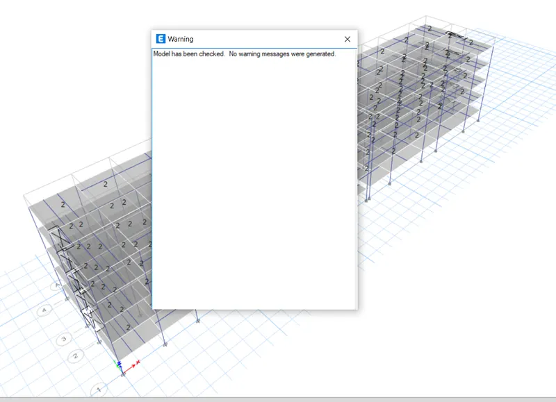
Check the Model any error and Analyze
After analysis and design,
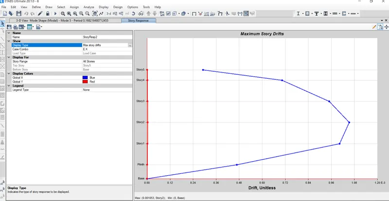
Storey drift for RSx case (within limit as per IS1893-2016)
Max Story Drift = 0.001053
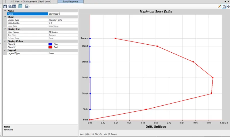
Storey drift for RSy case (within limit as per IS1893-2016)
max Story Drift = 0.00118
After analyse Design the Concrete Frame
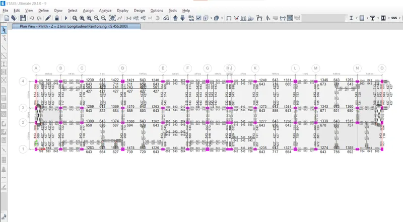
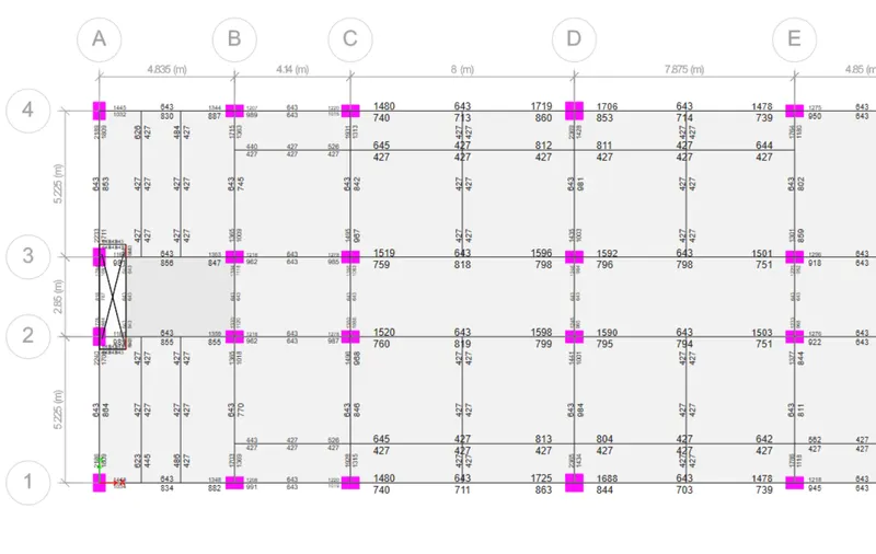
RC beam flexural rebar view
21) RC beam shear rebar view
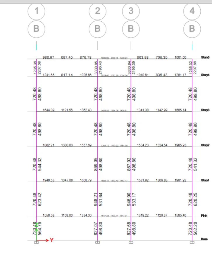
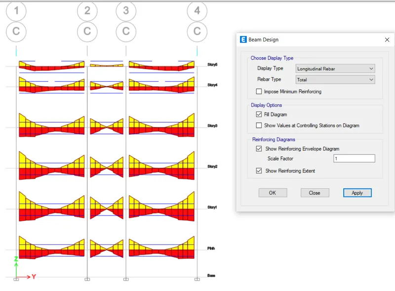
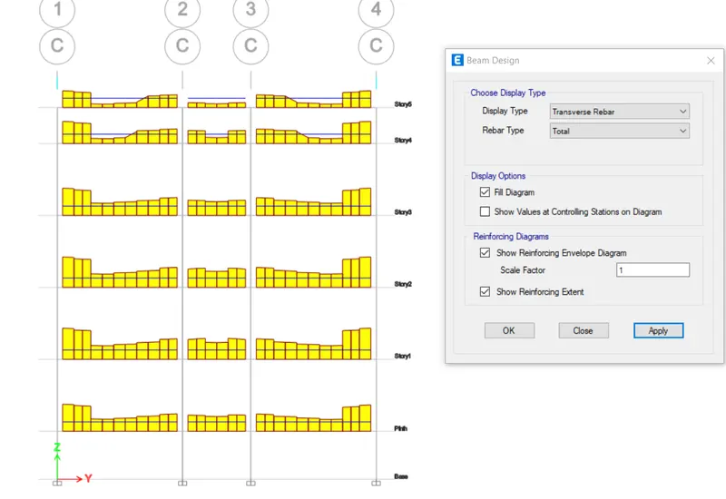
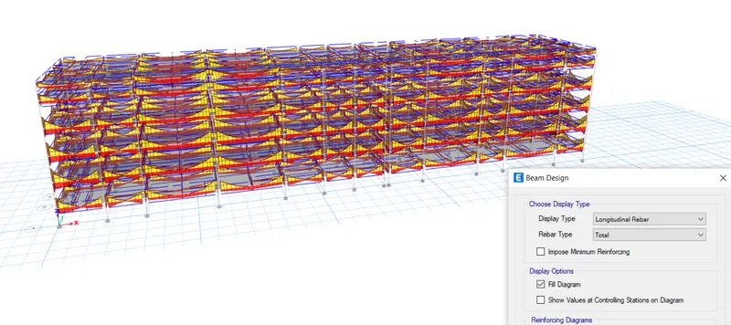
Hence; Frame and Slab Designing Finished now Design the foundation using Safe.
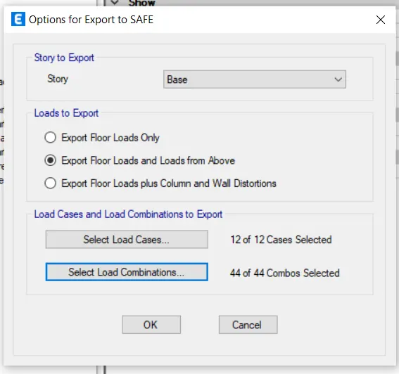
Go to File Tab in Etabs And export the Model in .f2k Format.
Modelling and Designing the Pile group foundation using SAFE software:
- Importing the f2k file in SAFE software
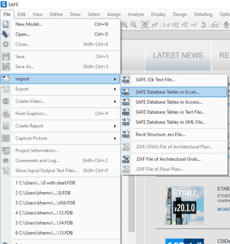
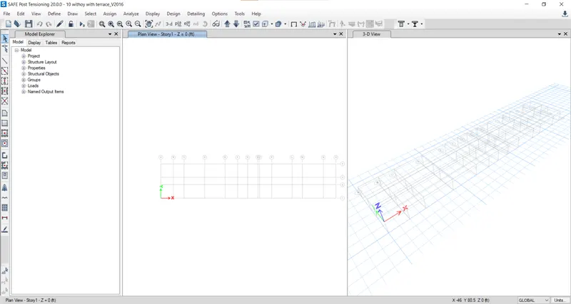
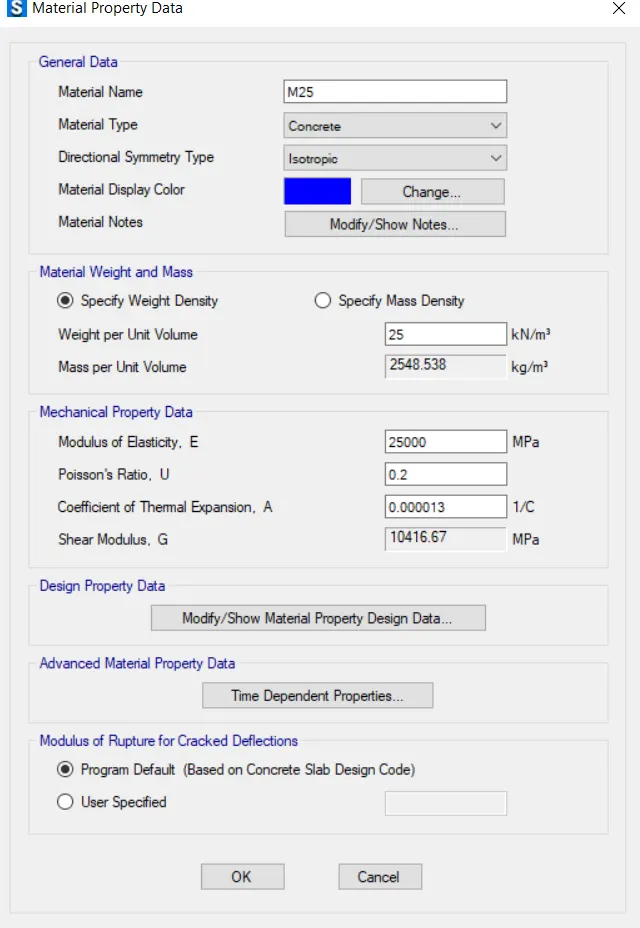
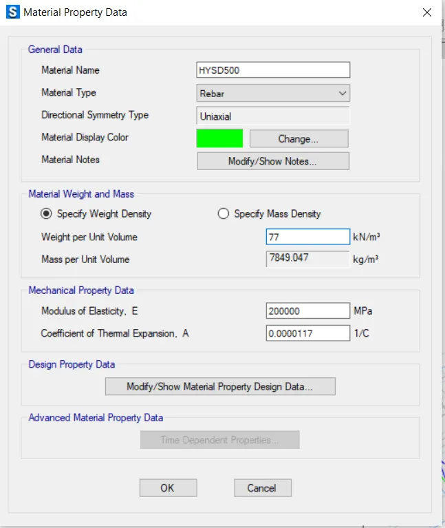
Define Materials
- Go to Define Tab and Select Material property.
- Select M25 concrete.
- Select Rebar as Fe 415 and Fe-500
Define Slab Property
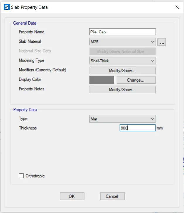
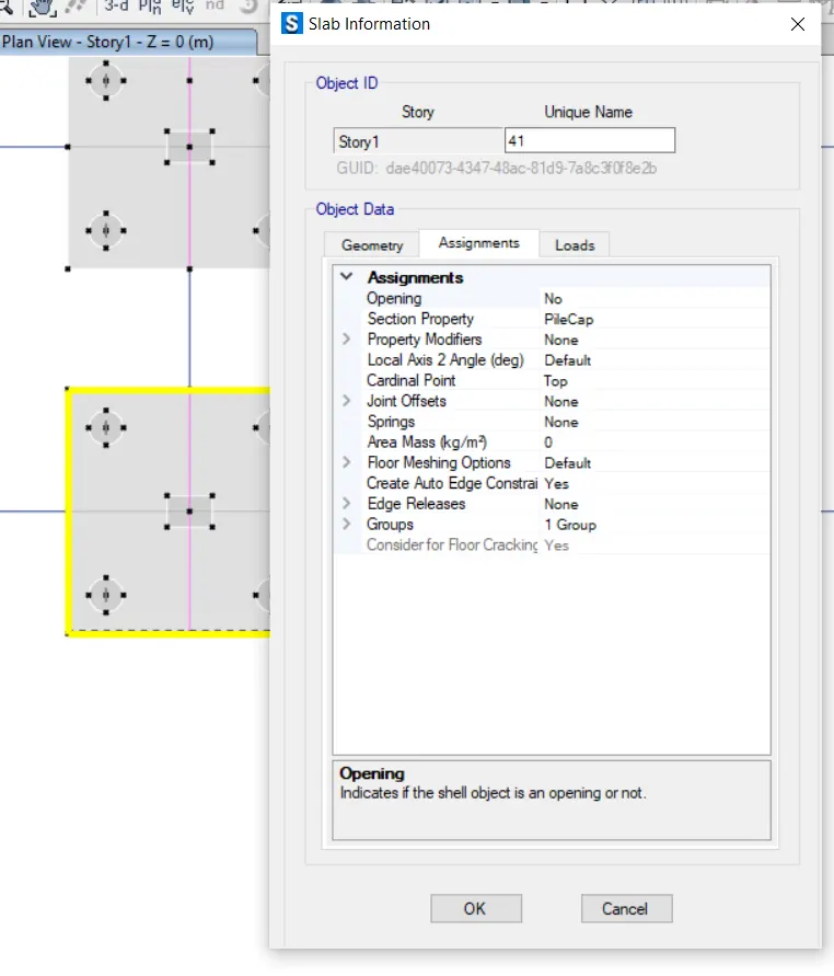
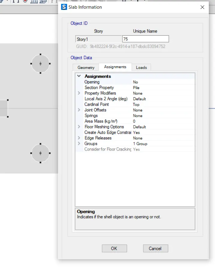
- Define Pile as Mat of thickness 800mm.
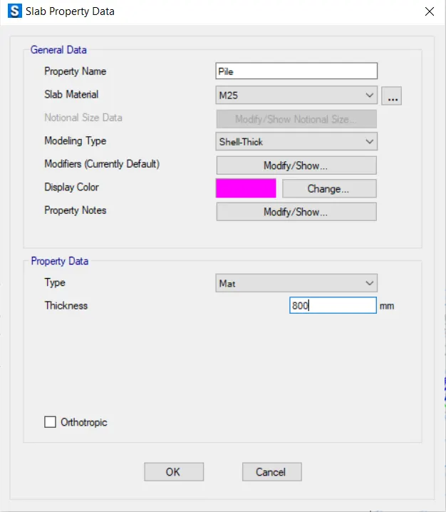
- Define PileCap as Mat of thickness 800 mm.
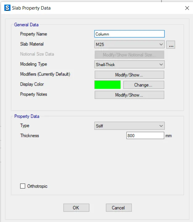
- Define Coulmn as Stiff of thickness 800mm
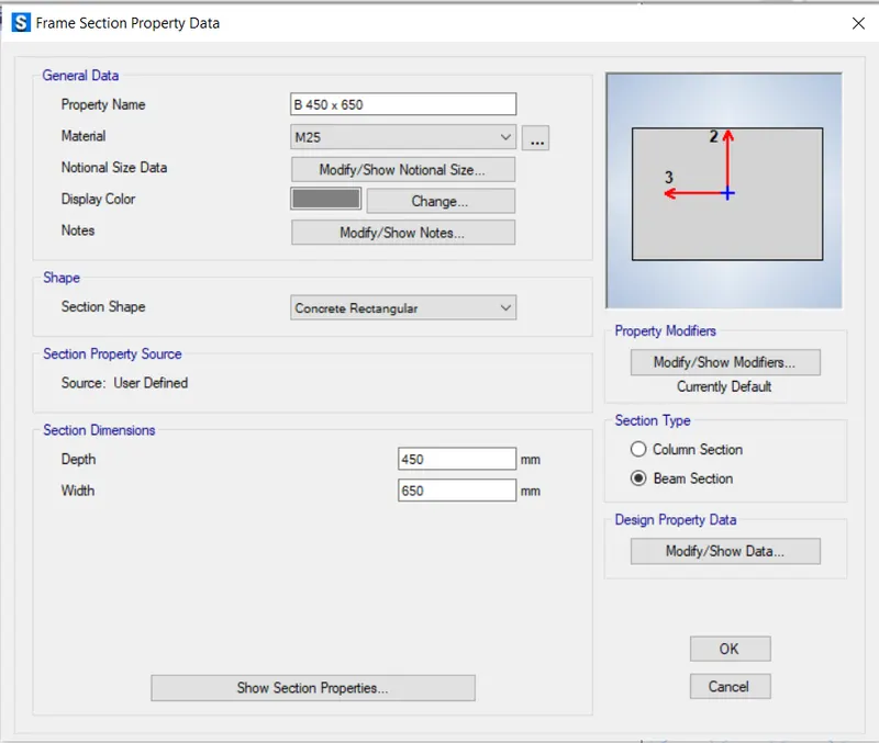
Define Frame Section For Tie Beam
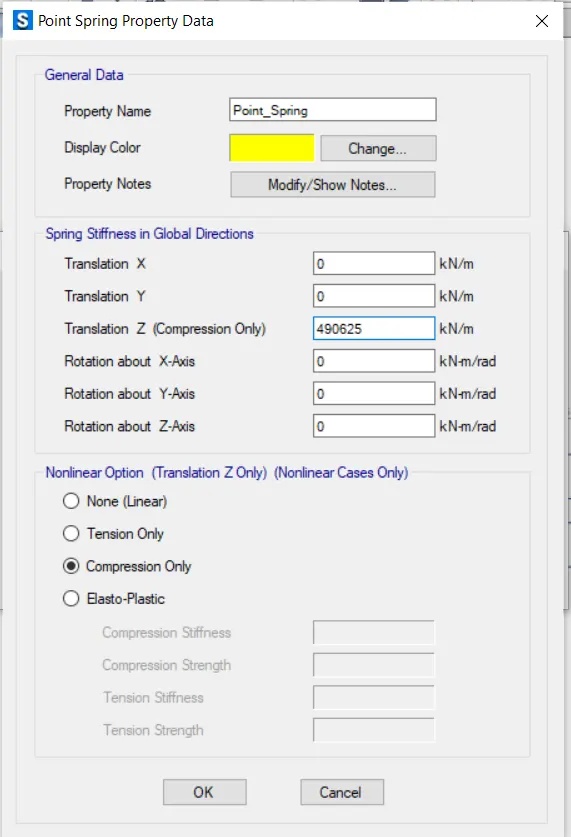
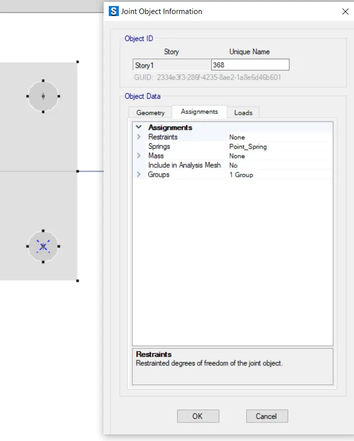
Point spring property assignment for piles
Spring constant = `(ExxA)/L`
= 490625
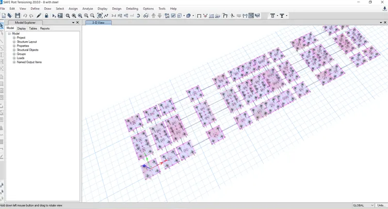
Drawing of Pile cap and pile points and stiff columns
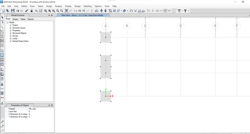
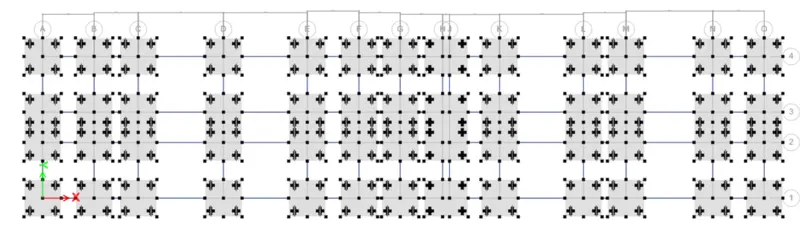
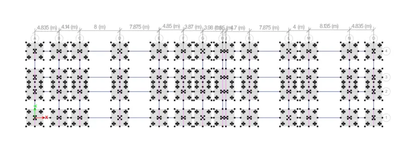
Assign Point spring to Pile Middle Joint.
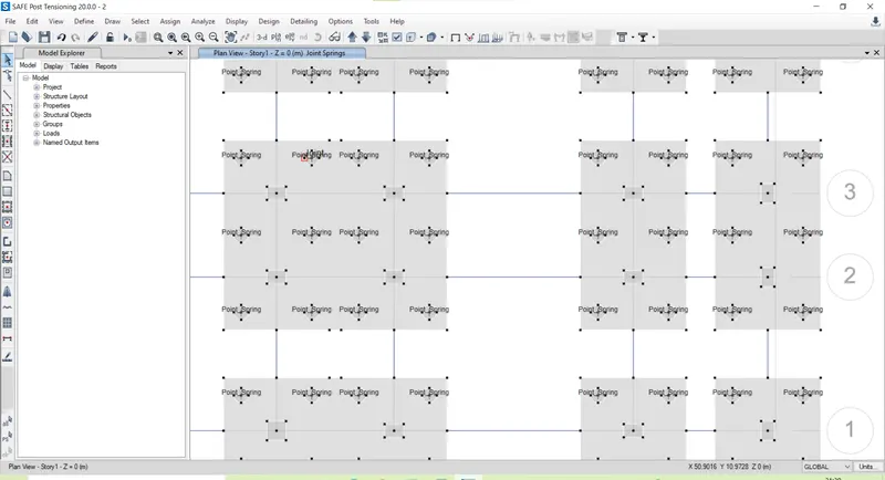
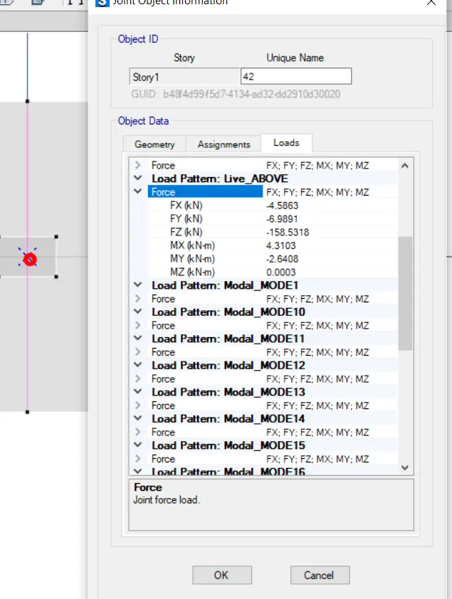
Before Analyzing Once verify all the member.
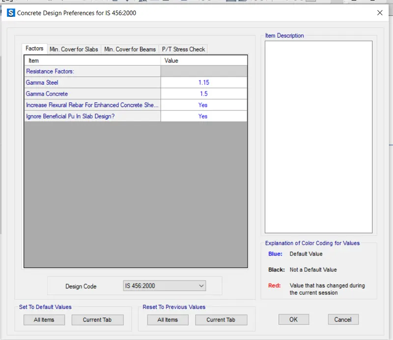
Now Analyze :
Result
Punching Shear within the limit > 1.
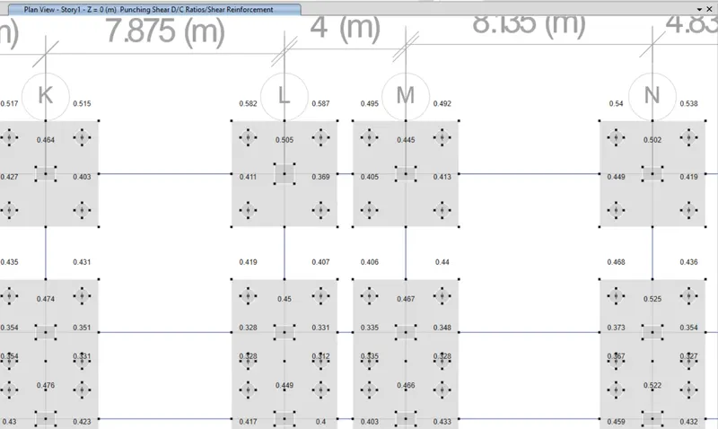
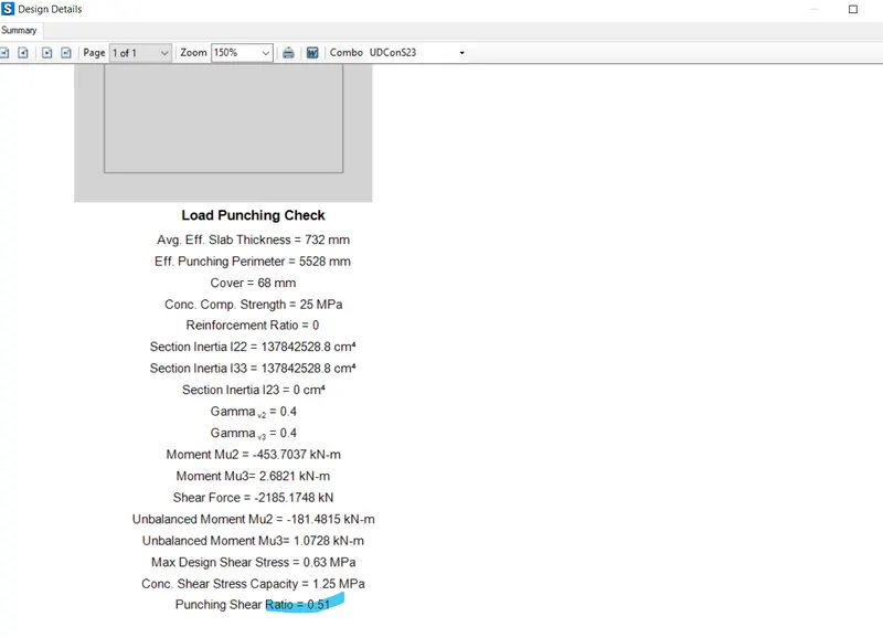
Support Reactions
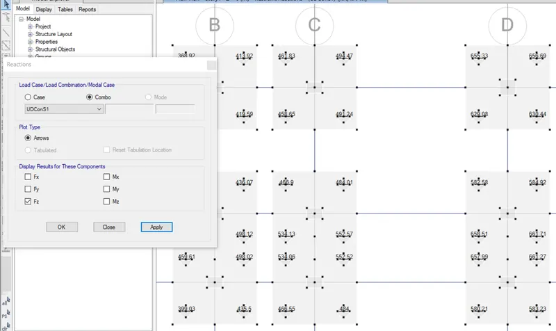
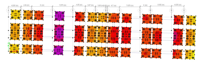
Displacement with in the limit >25 mm
Now Design the Strips.
Provision of X and Y design strips
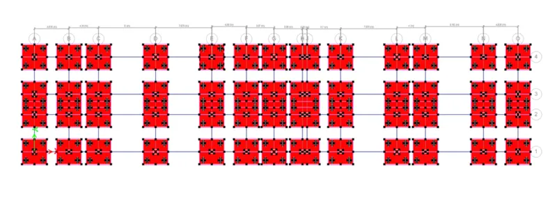
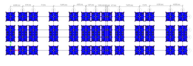
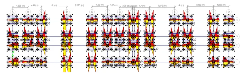
Max Top = 34230 mm^2
Max Bottom = 34230 mm^2
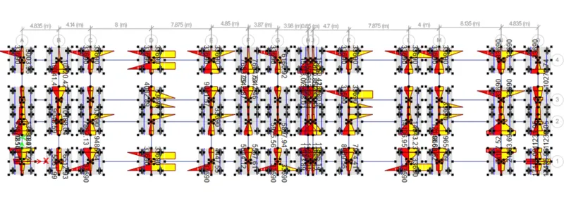
Max Top = 33690
Max bottom = 33690
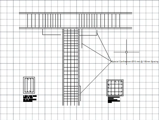
The Following details of Column and beam
Conclusion:
Thus the G+3 building is modelled and designed using ETABS. Also from the extracted support reactions, the suitable pile group is modelled and designed using SAFE software.