Fender Design Challenge
FRONT FENDER DESIGN
INTODUCTION
- Front fender is a covering part for the tyre and i protects the car as well as pedestrians from mud, stone scaterring from the tyre
- in ancient times full bumper type is used and in this type the blank wastage is more and now half bumper type is used and the blank wastage is also reduced
fender mountings
- there are five mounting positions for a fender and they are
- drip area mounting
- cowl mounting
- sill mounting
- bumper mounting
- body mounting
additional mount is baffle mount
DRIP mount
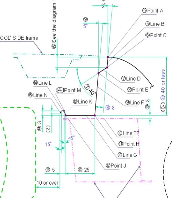
- for this mount master section is provided and also opening angle of 3 deg is given
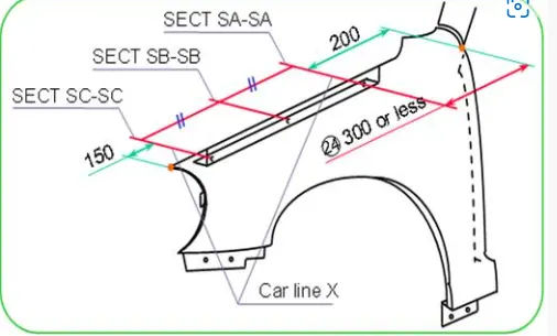
- then also the distance of the drip area from the front and back ends of the fender is also give
Creation process of all mounts in the front fender
- the given class A is taken
- the outer edge is offseted in face to about 10mm
- then as per blue print a sketch is created for the ends of drip area in top plane
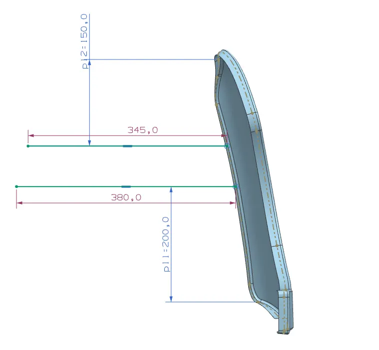
- then these lines are projected on the class A
- then curve on surface option is used to join the lines of drip area with the already offseted curve
- then similarl procedre of curve on surface is used to created the other mounts as shown below
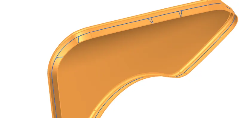
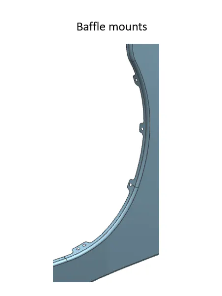
- other than the fendr mount baffle mounting region in the fender is also created using the same procedure
- then after the curves are drawn on the surface the trim sheet command is used to trim as shown below
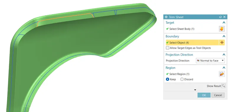
- The fender with after all intial trims is given below
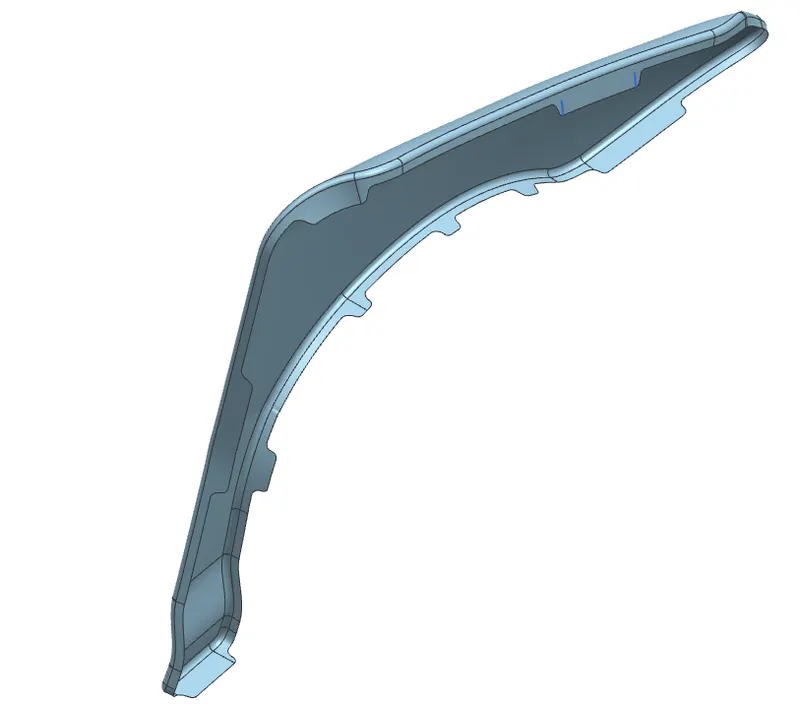
- reliefs are also provided at all the sharp corners
- After this the law extension is used to extent the mount regions and all mounts are extended only one time but for drip area the blue print is followed
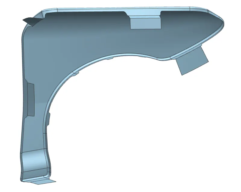
- drip area after appling fillets and openings as per master section is given below
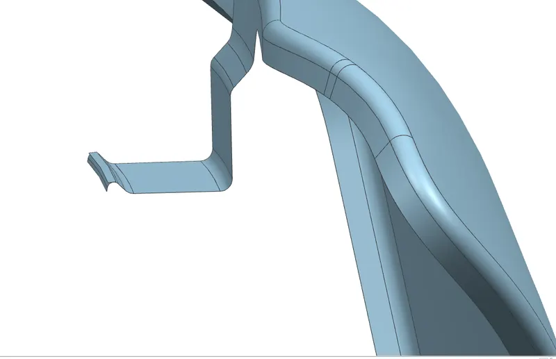
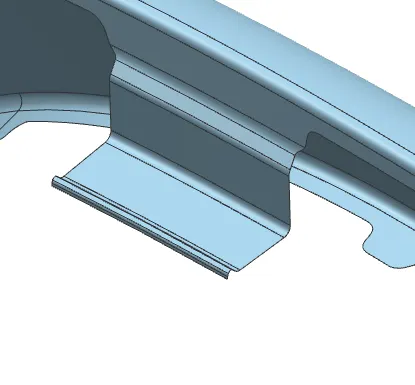
- all the mounts are creatred and now we want to create the screw mounting holes
- the holes for drip area is first created by sketch using datum and then using the sketch for emboss and holes creation
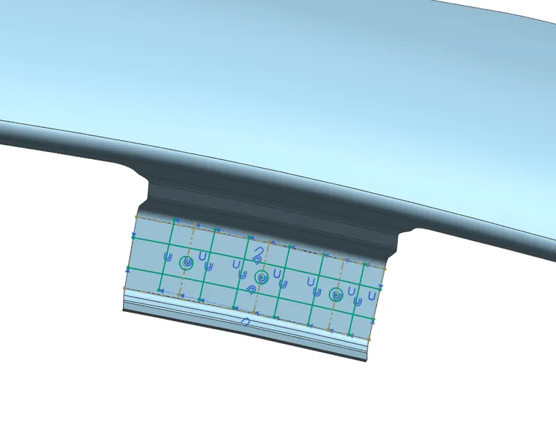
- the embosses are created using plane option to ensure the flastness of the emboss for screw mouting and a draft of 15 deg is also given
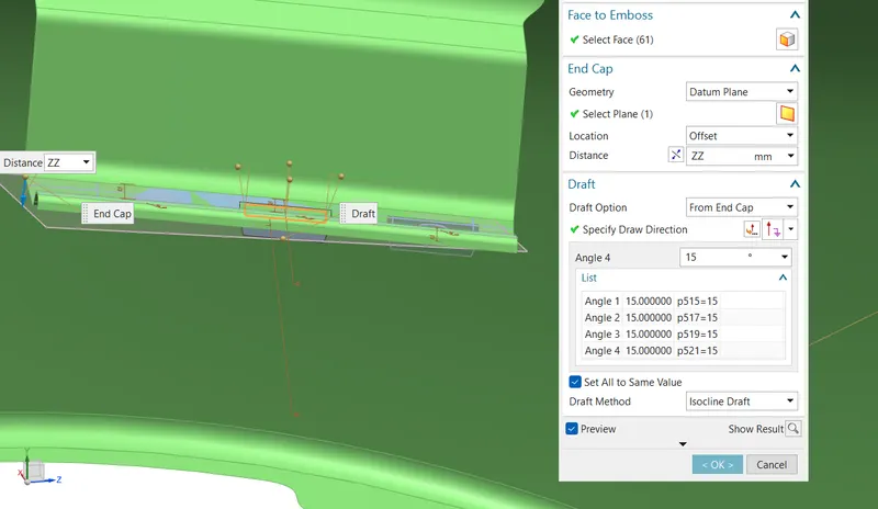
- after applying face blends and hole creation for the drip area
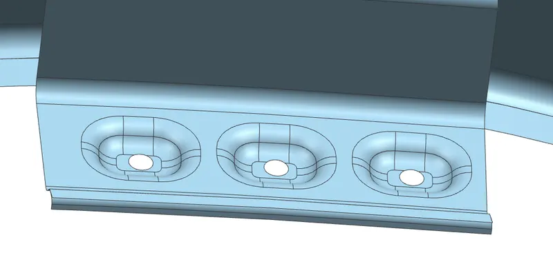
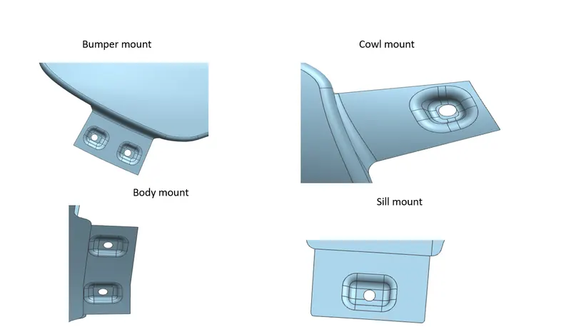
- similar procedures is used for the creation of embosses and mounting holes at all instances and the image for all mounts is given below
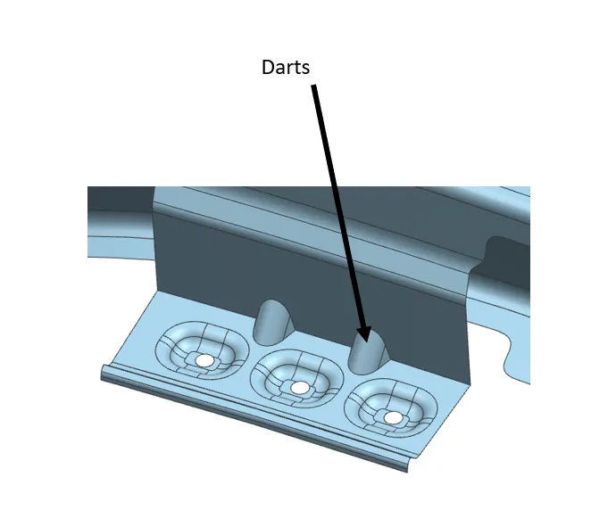
- to add additional strength darts are also added to the drip area
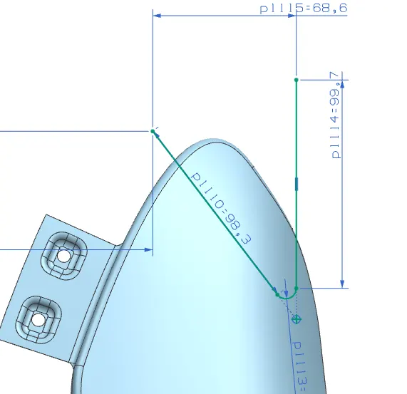
- for head light provision a small area in the front region of the fender is cut in the shape as follows
- then for the nvh perspective additional mounts are given to mount dampers
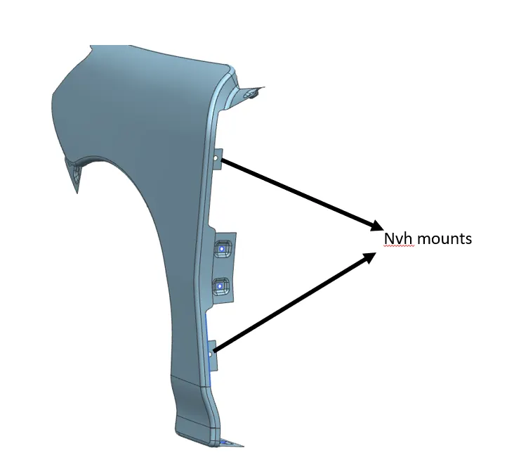
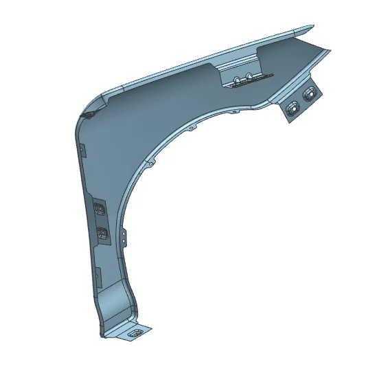
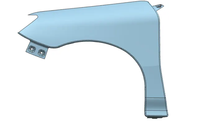
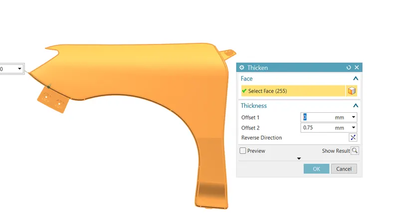
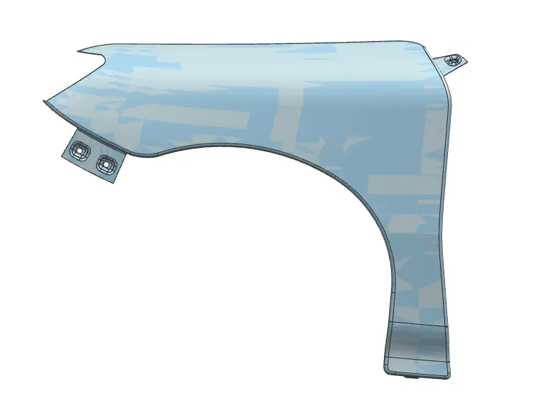
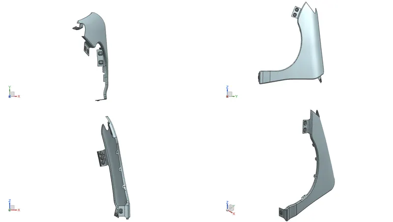
after all the process is made the final surface is sewed and the then thickened
the final surface
back side view front side view
then thickened surface
other rules followed in this design are given below
1.gap for emboss 6-8 mm from edges
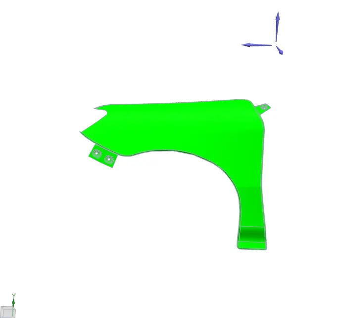
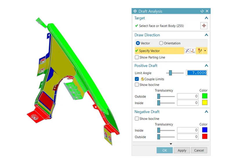
2. draft angle 7deg min
3.fillet min 3+thickness
4. holes also 6-8 from edges
draft ananlysis of fender
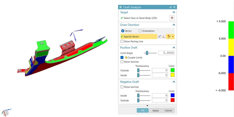
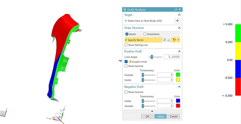
conclusion
thus the fender is designed as per the master section given for the drip area and various considerations and can be manufactured